Get in touch with Welong Company

How Drilling Mud Motors Work in Directional Drilling

Downhole drilling tools guide
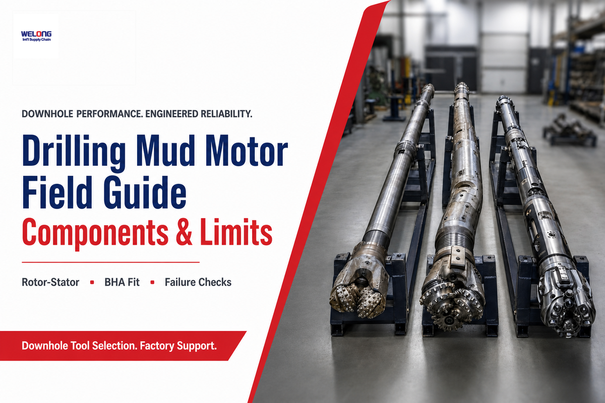
A Drilling Mud Motor is a positive displacement downhole drilling motor that turns drilling mud flow into bit rotation. This 2026 field guide explains the rotor, stator, bearing assembly, flow rate, differential pressure, torque, failure risk, and the point where rotary steerable systems may be the better tool.
Quick Specs Before You Read
This blog is not the product selector. Welong’s drilling mud motor model selector already owns model, inspection, and quote intent. At the time this workflow fetched the linked solution page, it listed 8 model entries and boundaries including 1 7/8 in to 9 5/8 in hole-size use, up to 2280 N-m working torque, 0-6 T bit pressure, 120-150 deg C rated temperature, and 0-3 deg adjustable bent housing options. Verify the live selector before using those values in an RFQ.
Use this guide to understand what those fields mean before sending an RFQ. Use the product page when the well plan is ready for supplier review.
Search paths differ by reader. A buyer comparing a downhole mud motor, directional drilling mud motor, HDD mud motor, or mud motor drilling setup needs mechanism, risk, and RFQ context before product selection. Readers searching for a drilling mud motor diagram, drilling mud motor price, or Drilling motor Power Section should use this guide for the working principle and the selector for quote intent. Honest tradeoff: this article will not claim the motor is always cheaper, because the common assumption fails when slide time, drag, hole cleaning, or RSS alternatives change the section cost.
What a Drilling Mud Motor Does Downhole
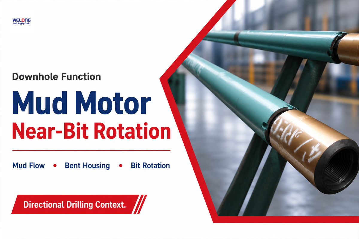
In the bottom-hole assembly, a mud motor sits between the drill string and the drill bit. Drilling fluid from the mud pumps flows through the tool. Hydraulic energy becomes mechanical rotation inside the power section, so the drill bit can turn downhole even when the full drill string is not rotating from surface.
SLB’s positive displacement motor glossary gives the clean authority definition: drilling fluid powers a downhole motor and the motor sends mechanical power to the drill bit. Simple definition, hard field decision. Every driller still has to match flow rate, differential pressure, bend angle, formation response, and bearing load.
One common assumption is that a directional drilling mud motor is only a steering device. Too narrow. In motor drilling, it also changes bit energy, rate of penetration, and surface interpretation. If the motor stalls, the bit stops first; surface rotary behavior may still mislead the crew. For that reason, this guide treats a downhole mud motor as a power, steering, and risk-control tool.
For product intent, route back to Welong drilling mud motor specifications. For education, keep reading here.
How the Rotor-Stator Power Section Turns Mud Flow into Bit Rotation
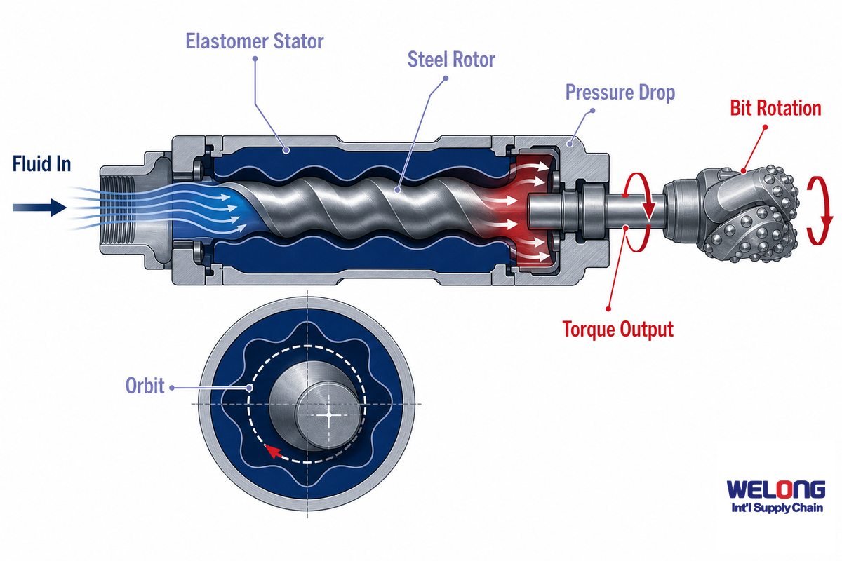
Inside the power section, a steel rotor runs inside an elastomer-lined stator. Different rotor and stator lobe counts create sealed cavities. As drilling fluid moves through those cavities, the rotor follows eccentric motion and sends rotation through the transmission to the bit. That is the positive displacement principle.
How does a drilling motor work?
Positive displacement drilling motor work starts when drilling mud is forced through the rotor-stator cavity set. Flow creates motor speed; pressure drop creates force that becomes torque. Output is not a universal rpm rule. Rotor/stator geometry, lobe count, mud density, solid load, temperature, and the supplier power curve all matter.
Data quality is the reason this matters. Patent work on drilling motor power output ties differential pressure, torque variation, and motor rotation rate together. A 2024 IntechOpen chapter on positive displacement motor condition prediction also frames surface and downhole data as the basis for motor health, not just a post-run report. In practice, a 300 psi or 400 psi signal is only useful when the crew knows what normal looks like for that motor setup.
For an industrial buyer, the risk is not academic. A 300 psi pressure shift, 80 rpm speed target, or 24 hours run plan can mislead the crew if the hydraulic application is not tied to the supplier curve. Welong should confirm the motor curve, stator fit, and inspection basis because a wrong setup can fail before the field team sees a clear surface warning.
Honest version: a mud motor will not turn poor hydraulic planning into a clean run. If pump output, nozzle pressure loss, annulus pressure loss, and motor pressure drop are mixed together, the crew may treat a normal load change as a stall or miss a real stall until stator damage has started.
Main Components: Power Section, Transmission, Bearing Assembly, Bent Housing
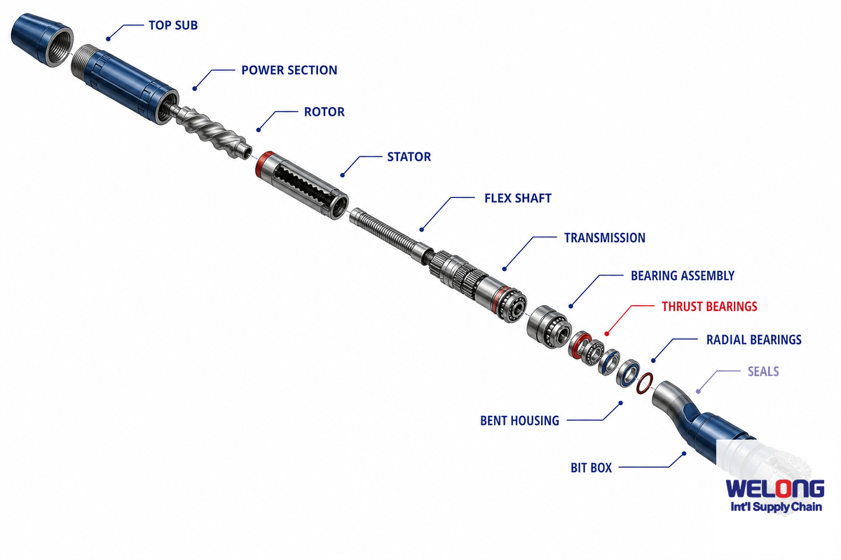
Before reading a spec sheet, the buyer should know which parts drive risk. Welong engineers usually ask for the well section, hole size, bit program, mud type, connection, flow window, and desired bend angle before a motor is quoted because each component has a different failure path.
| Component | Main job | Field check |
|---|---|---|
| Power section | Converts hydraulic flow into torque and rpm | Match flow rate, pressure drop, stator fit, and temperature. |
| Rotor | Runs eccentric motion inside the stator | Check lobe count, wear, coating, and connection fit. |
| Stator | Creates sealing cavities for positive displacement | Check oil-based mud, 120-150 deg C exposure, and swelling risk. |
| Transmission | Transfers rotor motion to the drive shaft | Check bend angle and side-load limits. |
| Bearing assembly | Carries axial and radial bit load | Check weight on the bit, mud lubricity, and expected run hours. |
| Bent housing | Sets steering tendency in sliding mode | Confirm 0-3 deg need against dogleg and BHA plan. |
| Connections | Join the motor into the drill string | Use the connection checker before purchase. |
API Spec 7-1 enters the conversation here. It is not a mud motor power-curve rating; it is an adjacent drillstem-interface standards area. Because edition, errata, and addendum records can change, check the current API publication record, connection data, and the supplier drawing together instead of treating a thread label as the full evidence package.
Flow Rate, Differential Pressure, RPM, and Torque: How Performance Is Set
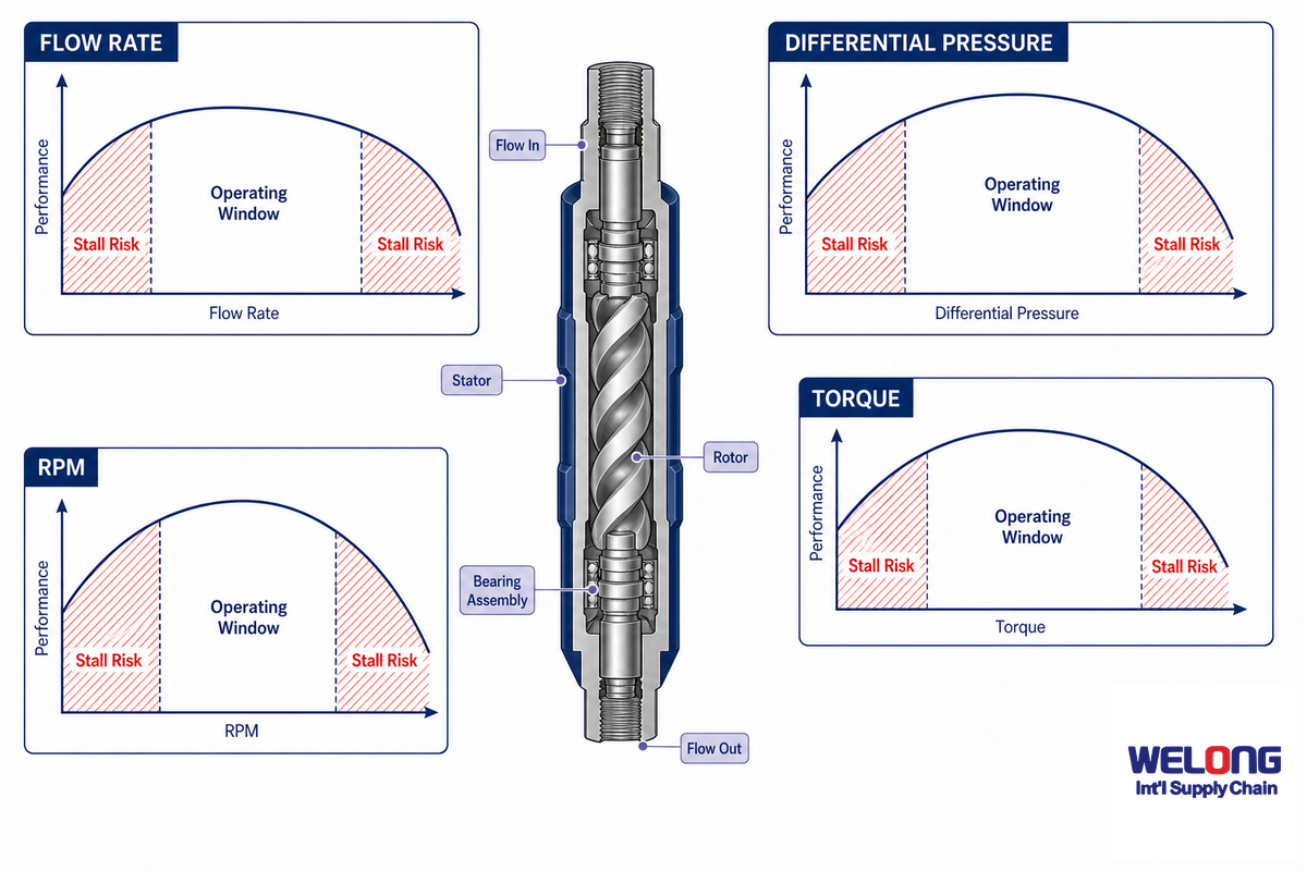
Flow rate, differential pressure, rpm, torque, and horsepower are linked, but not interchangeable. Flow mainly sets speed. Differential pressure reflects load. Torque rises with load until stall risk appears. Horsepower depends on both torque and speed. A supplier curve is the governing source because two motors with the same outside diameter can behave differently when the number of lobes, elastomer fit, and flow window change.
Drilling Manual guidance discusses pressure allocation and motor operating pressure, while academic modeling has reported less than 6% average error under a 300 psi differential-pressure condition. Those numbers should not be pasted into an RFQ as universal values. They show why pressure, torque, and rpm must be read as a connected system.
| Reading | Why it matters | Check before use |
|---|---|---|
| 300 psi | Modeling benchmark cited for pressure-error control | Do not treat it as the motor limit. |
| 400 psi | Example load signal in condition work | Confirm against supplier curve. |
| 500 psi | Selection-context pressure note | Separate motor drop from nozzle loss. |
| 1.5 MPa | Pressure plan marker for hydraulic review | Check pump margin. |
| 2.0 MPa | Load-change warning band | Set a stop-running rule. |
| 80 rpm | Low-speed motor response check | Confirm bit rpm, not only rotary rpm. |
| 120 rpm | Common mid-range planning marker | Match bit and formation. |
| 180 rpm | High-speed wear-risk marker | Review bearing load. |
| 50% | Possible pressure-allocation share | Keep annulus and nozzle loss separate. |
| 60% | Upper allocation check in planning | Leave margin for cuttings load. |
| 24 hours | Run-life planning interval | Ask for inspection record before re-run. |
| 30 min | Short slide-decision review interval | Recheck toolface and drag trend. |
| 60 sec | Rapid stall-response marker | Train crew response before run. |
| 3.4 MPa | High hydraulic-stress review point | Check stator heat and bearing load. |
| 6% | Model-error benchmark from literature | Treat as source-specific, not universal. |
For a Welong RFQ, use the flow range, expected differential pressure, bit size, hole size, motor bend angle, and temperature together. If you already know the drill pipe and bottom-hole assembly envelope, compare it with the drill pipe baseline and the drill collar guide.
Where Mud Motors Win: Directional, Horizontal, HDD, and Hard-Formation Runs
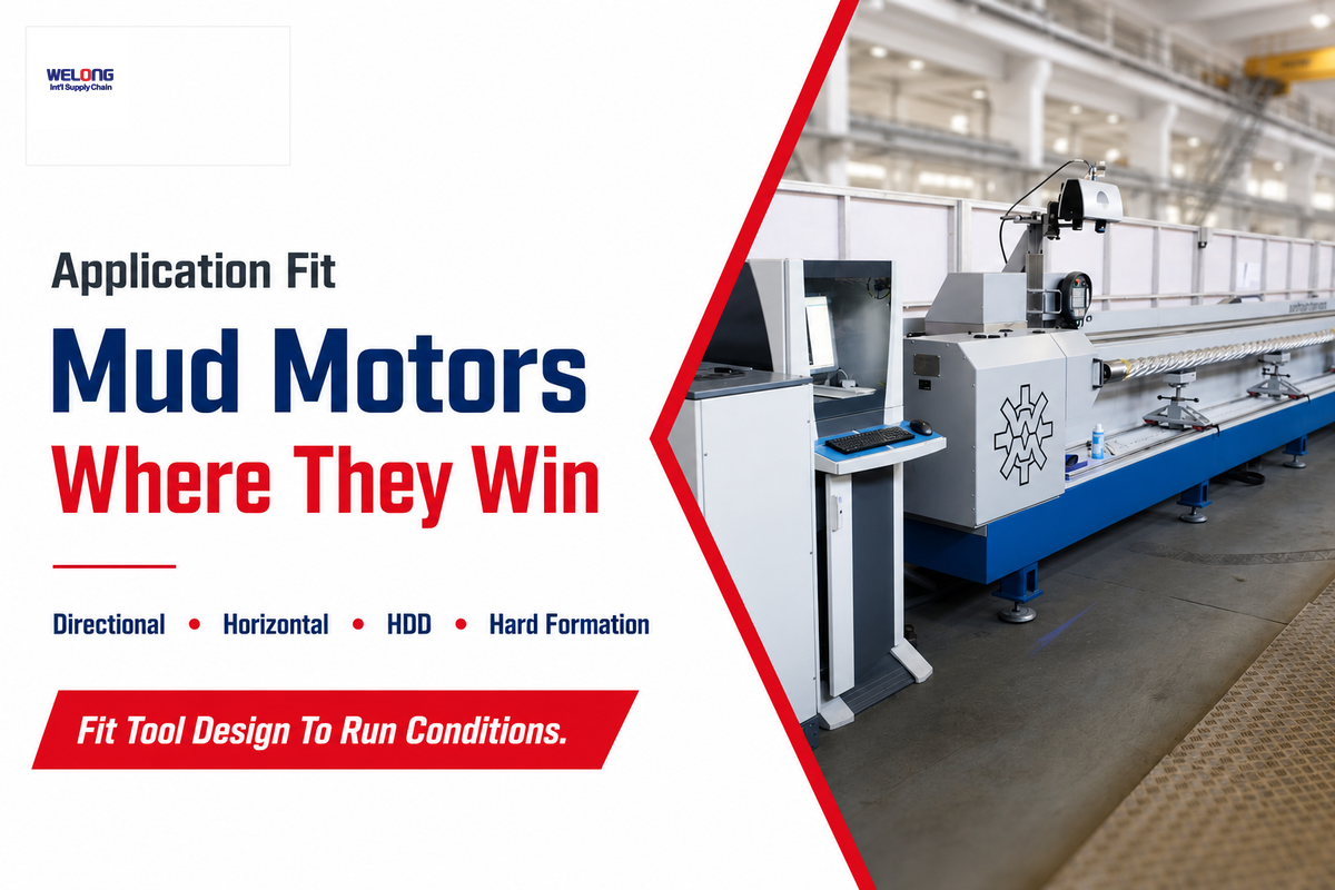
Directional drilling mud motor value appears when downhole bit power and steerability solve a real section problem. The tool may fit build sections, tangent corrections, horizontal directional drilling, and hard-formation intervals where surface rotation alone is not enough. Local bit rpm can also improve penetration when high drill string rpm is not wanted.
4-Window Mud Motor Fit Map for Tool Choice
| Window | Use case | Motor fit signal | Warning sign |
|---|---|---|---|
| 1 | Build section | Defined dogleg, short slide interval, clear target | Long slide time creates drag. |
| 2 | Horizontal hold | Bit needs local rpm while drill string rotation is limited | Hole cleaning becomes weak. |
| 3 | HDD crossing | Steerable mud motor helps maintain path in hard ground | Fluid window is tight. |
| 4 | Hard formation | Bit energy rises without excess surface rpm | Stall cycles rise. |
| 5 | Correction run | Short directional control task | RSS may beat repeated trips. |
| 6 | Budget-limited well | RSS value does not repay cost | Cheap choice adds wellbore cost. |
| 7 | MWD-limited BHA | Motor geometry leaves enough signal and spacing | Toolface control is unstable. |
| 8 | Inspection-driven purchase | Supplier can document stator, bearing, and connection checks | Only a price sheet is offered. |
| 9 | Spare tool planning | Known hole size and flow window repeat across wells | Mixed thread and bend specs create warehouse risk. |
Familiarity is the trap. A field note that “you lose a lot of the weight to drag on the low side of the hole” explains why slide time can erase the price gain. Welong can supply the tool, but the well plan still has to prove that motor drilling is the right call.
Mud Motor vs Rotary Steerable System: The Boundary, Not a Winner
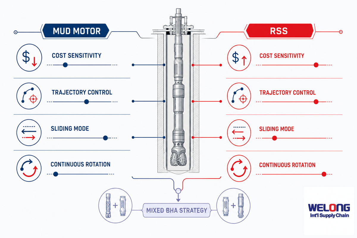
Mud motor versus rotary steerable system is not a brand contest. Think of it as a boundary. For many directional drilling operations, the motor may be the lower-cost tool. RSS may be the better choice when continuous rotation, cleaner wellbore geometry, and steering precision change the economics. Some hybrid or assisted steering systems sit between conventional sliding motors and full RSS, so the RFQ should ask what steering method is being compared.
Expert note: Drilling Contractor’s 2026 RSS coverage frames the issue around higher RSS cost, faster wells, and rising complexity. That frame matters: the tool that looks expensive at surface may be justified if it prevents slow sliding, cleanup risk, or a poor wellbore.
What are the differences between mud motor and RSS in directional drilling?
Steerable mud motor work uses a bent housing and slide/rotate control. RSS steers while rotating, which can help hole cleaning and reduce tortuosity. Trade press has reported cases where high-performance mud motors can save operators more than 50% per day over using an RSS, while other wells justify the RSS premium through speed and precision.
| Decision factor | Mud motor question | RSS question |
|---|---|---|
| Tool cost | Will savings survive slide time? | Will cost buy enough time or wellbore quality? |
| Steering | Can bent housing and toolface control hit target? | Does continuous steering reduce risk? |
| Hole cleaning | Will sliding trap cuttings? | Does rotation solve a section risk? |
| BHA complexity | Are MWD spacing and connection limits clear? | Can the crew support extra tool planning? |
JPT/SPE guidance also notes that slide-drilling optimization differs between RSS and mud-motor setups because the mud motor adds cost functions and constraints. Counter-intuitive point: a motor is not always the simpler plan once the whole well section is counted.
Common Failure Modes: Stator Chunking, Debonding, Plugging, and Temperature Swell
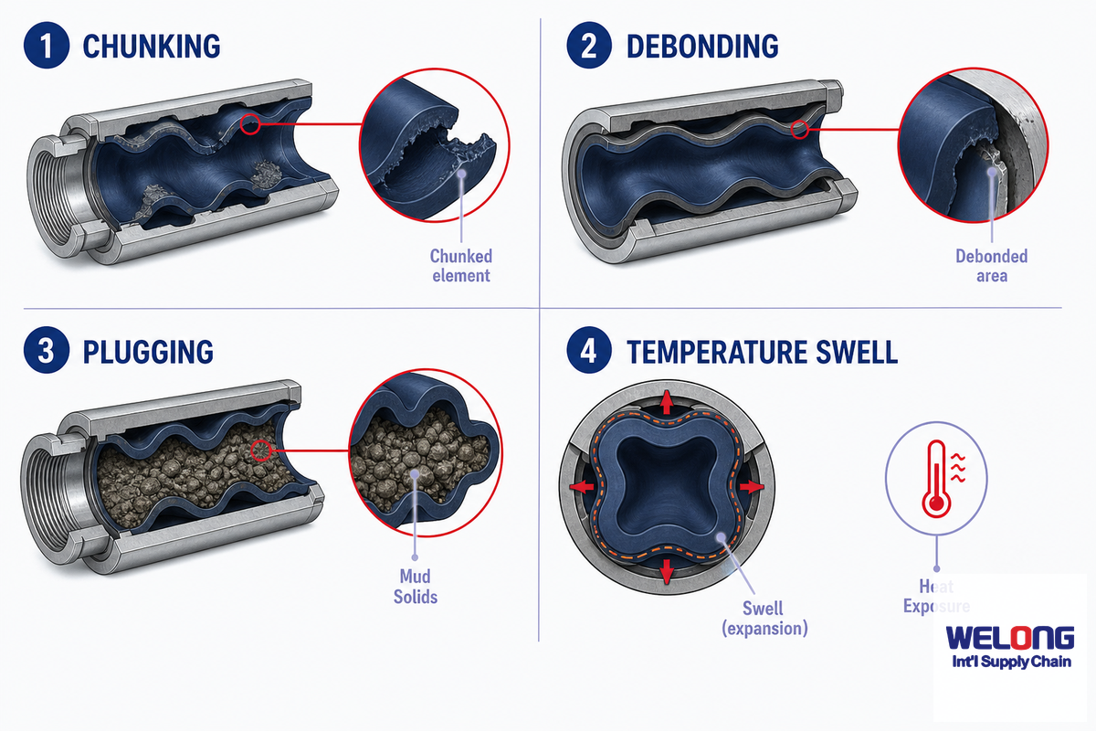
Use the Rotor-Stator-to-Run-Risk Ladder to move from mud chemistry, to fit, to load, to heat, then to inspection. Failure rarely begins as a neat label. Early signals often appear as rising differential pressure, unstable torque, reduced rate of penetration, or a stall pattern that gets explained away until the stator or bearing section is damaged. Behind those symptoms are driver groups: rotor/stator design, elastomer material, drilling fluid chemistry, motor speed, differential pressure, and downhole temperature.
9-Row Mud Motor Failure Mode Table
| Type | Failure mode | Likely field signal | What to request |
|---|---|---|---|
| Elastomer | Stator swelling | Higher pressure at same flow | Mud type and 120-150 deg C rating check |
| Elastomer | Chunking | Torque noise and flow restriction | Stator inspection record |
| Bond | Debonding | Power loss and rubber debris | Manufacturing and heat history |
| Hydraulic | Plugging from solid load | Pressure spike at stable pump rate | Lost circulation material plan |
| Load | Stall damage | Repeated pressure peaks | Differential pressure limit and response procedure |
| Bearing | Axial overload | Vibration, wear, short run life | WOB, bit plan, bearing assembly data |
| Geometry | Excess bend side-load | Steering gain with mechanical risk | 0-3 deg bend review |
| Connection | Thread mismatch | Make-up delay or rejection | Connection drawing and gauge check |
| Operations | Wrong surface reading | Bit response differs from screen story | MWD, bit rpm, and rotary rpm review |
Oil-based mud, high temperature, annulus loading, and weight on the bit all change this table. Welong’s inspection handoff should be read with the mud program, not as a stand-alone sales claim. If jars are part of the assembly, compare the motor plan with the drilling jars guide.
How to Read a Mud Motor Specification Before Asking for a Quote
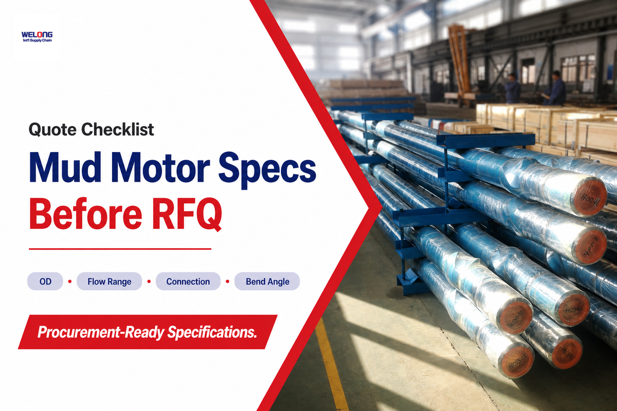
Start a mud motor RFQ with the well section, not with the cheapest model line. Your specification should state hole size, bit size, connection, motor outside diameter, bend angle, flow rate, expected differential pressure, mud type, temperature, formation, and inspection need. One missing field can turn a fast quote into a wrong configuration.
Welong’s linked solution page was used as first-party workflow context, not as an independent industry benchmark. It gives the reader a sense of model range and operating fields, while the live product page remains the right place for the full table and current values. This blog uses those fields only to explain what a buyer should check.
For a field application, the evidence chain is practical: a missing connection drawing, a 500 psi pressure assumption, or a 120 rpm bit-speed target can push the wrong motor into the RFQ. Welong can review the spec, but the buyer still needs to state the drilling operation, mud type, and inspection record expected before price is discussed.
For heavy bottom-hole assemblies, compare motor fit with the heavy weight drill pipe guide. For cleanup or wellbore conditioning after casing work, review the casing scraper notes. The goal is to make the motor one part of a tool string, not a lonely SKU.
RFQ handoff: Send hole size, bit type, flow window, differential pressure target, connection, bend angle, mud type, temperature, MWD spacing, and required inspection record. Then ask the supplier to confirm the motor curve and connection drawing before price.
Field Checks Before Running a Mud Motor in the BHA
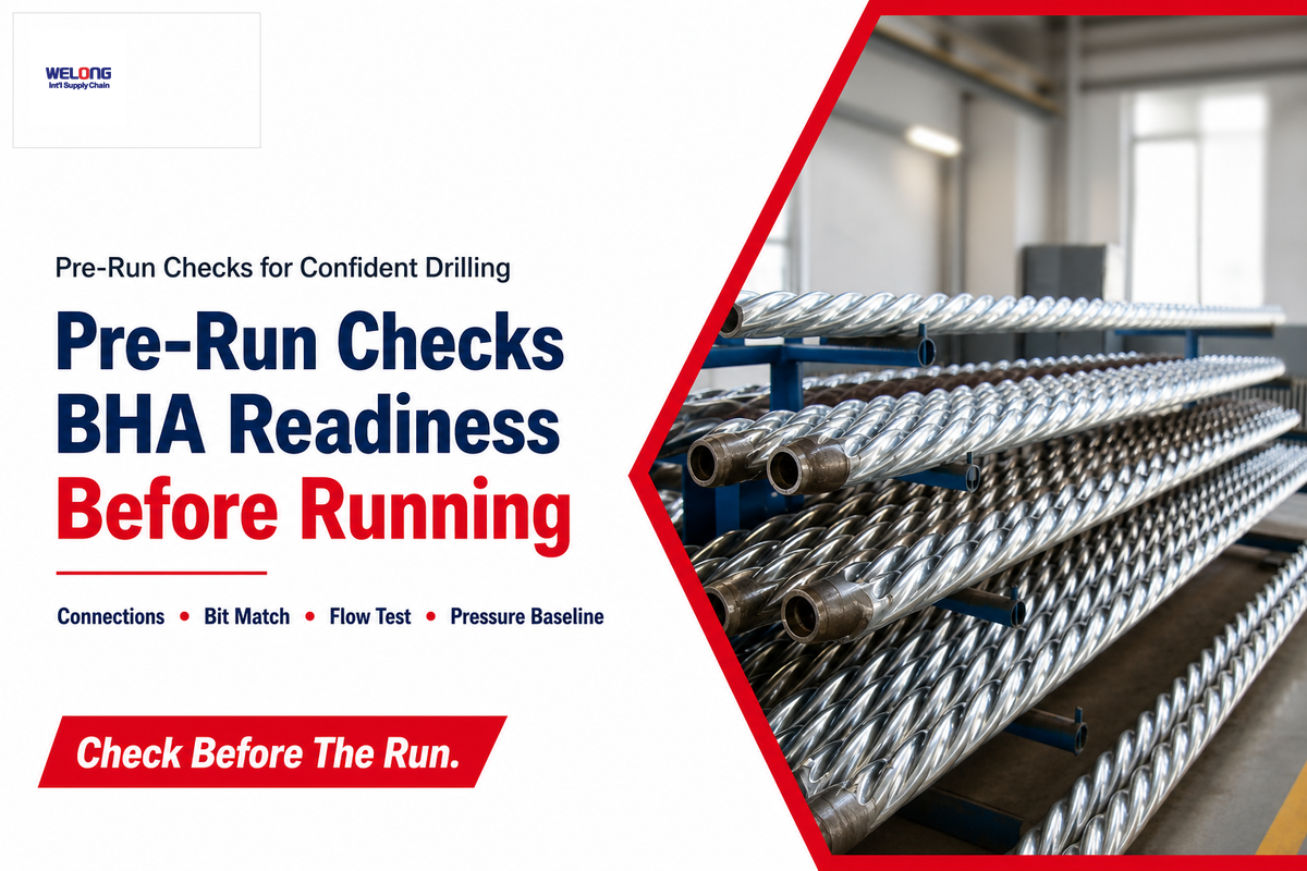
Before the motor is run, the team should check the BHA like a system. Motor connections include drill pipe, collars, MWD, bit, jars, stabilizers, and surface pumps. A 1 in mismatch, an unplanned 500 psi pressure loss, or a missing thread drawing can create avoidable delay.
- Confirm bit size, hole size, and motor outside diameter.
- Confirm connection and torque make-up data with drawings.
- Check flow of the drilling fluid against motor curve and nozzle plan.
- Check expected differential pressure, stall procedure, and pressure trip points.
- Check bend angle, MWD spacing, and directional control plan.
- Check mud type, solid load, oil-based exposure, and lost circulation material.
- Check weight on the bit, bearing load, and expected run hours.
- Check post-run inspection requirements before the tool ships.
Field checks also protect content intent. If the reader has reached this point, they likely need a supplier conversation. Use the mud motor model selector or open the RFQ popup with the checklist above.
What Is Changing in 2026: Reliability Models, Sensors, and RSS Coexistence
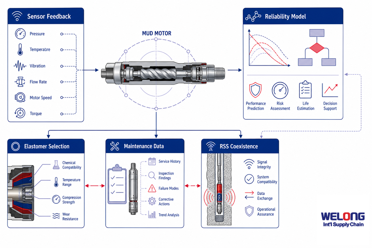
For 2026, the angle in this article is not a big growth claim. DataForSEO trend data for this keyword group showed no rising count and a September 2025 spike, so the safer story is reliability and decision support. Useful change is coming from condition prediction, downhole sensor data, and better surface interpretation.
In the field, that means the next buyer question is not only “What model?” It is “What hydraulic data, rpm window, 300 psi or 400 psi pressure behavior, and post-run inspection record will prove the motor stayed inside its working envelope?” Welong’s role is to connect those data points to the tool record rather than treat reliability as a slogan.
IntechOpen’s 2024 work on positive displacement motor condition and performance prediction points to surface and downhole data, while the patent trail connects motor power output to differential pressure, torque variation, and rotation rate. That is where the next buyer questions should go: What data will the supplier use, what curve will the rig team see, and what is the stop-running rule when pressure behavior changes?
RSS will keep improving. Mud motors will still hold a place where cost, field familiarity, and bit power matter. The right call is not always the most advanced tool; it is the tool whose risk profile fits the section. For the boundary conversation, Welong’s PDM and RSS fit guide can sit beside this article in the internal link path.
FAQ
What is a drilling mud motor?
In a drilling mud motor, a downhole positive displacement motor receives mud flow through the power section, moves the rotor inside the stator, and sends mechanical power to the drill bit. Directional drilling, horizontal directional drilling, and some performance drilling work use it when local bit rpm and steering control are needed.
How does a mud motor steer a wellbore?
Steerable mud motor systems use a bent housing and toolface control. During sliding, the drill string is held in a set orientation so the bend points the bit along the planned path. During rotary drilling, the string rotates and the path tends to smooth out. Tradeoff: sliding can reduce hole cleaning and rate of penetration, so steering decisions must be limited to the section that needs them.
What is the difference between a mud motor and a mud pump?
Mud pump hardware stays at surface and pushes drilling fluid down the drill string. Mud motor hardware runs downhole, receives that flow, and turns part of the hydraulic energy into rotation at the bit. Pump output supplies flow and pressure; motor geometry uses that flow and pressure to create speed and torque.
Can a mud motor be used in straight-hole drilling?
Yes, if the goal is extra bit rpm, hard-formation performance, or controlled motor drilling. Directional work is not the only use.
What causes mud motor stator damage?
Stator damage can come from heat, oil-based mud, chemical mismatch, solid loading, repeated stalls, excess differential pressure, or poor rotor/stator fit. Temperature exposure around 120-150 deg C, lost circulation material, and high pressure spikes deserve special review. Damage may show as pressure noise, falling power, rubber debris, or short run life. Request stator material data, inspection notes, and a stop-running rule before the motor ships.
What should be included in a mud motor RFQ?
Include hole size, bit size, connection, flow rate, expected differential pressure, mud type, temperature, formation, bend angle, MWD spacing, weight on the bit, and inspection needs. If the buyer only sends outside diameter and price target, the supplier has to guess at the run condition. Better RFQ data lets Welong confirm the motor curve, connection drawing, and delivery scope.
References
- SLB Glossary: Positive displacement motor
- IntechOpen: Positive Displacement Motor Condition and Performance Prediction
- ScienceDirect: PDM theoretical modeling abstract
- API: Standards addenda and errata
- API: Spec 7-1 Second Edition Errata 2
- Google Patents: drilling motor power output
- Drilling Contractor: RSS vs mud motors
- JPT/SPE: slide drilling guidance
Why Buyers Work With Welong
About Welong Engineering Support
China Welong supports oilfield buyers with engineered supply-chain service for drilling tools, well-control equipment, rig-floor tools, casting parts, and industrial forged components.
Project Review Before RFQ
We help buyers compare tool family, material route, API or ISO requirements, inspection records, supplier capability, delivery risk, and documentation needs before a purchase decision is finalized.
Request An Oilfield QuoteCompany Profile // Data Sheet
CompanyChina Welong International Supply Chain
BrandWelong
CountryChina
Business TypeOilfield tools and industrial supply-chain partner
Main ProductsDownhole drilling tools, fishing and milling tools, wellhead and well-control equipment, oilfield hoses, rig-floor handling tools, mill rolls, and forgings
Engineering CapabilityTool-family selection, specification envelope review, API / ISO reference support, material traceability, inspection coordination, and supplier-route comparison
RFQ Data NeededTool type, size, connection, rating, grade, standard, quantity, drawings, and delivery target
Websitewelongoiltools.com
![Casing, Tubing & Drill Pipe Elevators [Field Guide]](https://welongoiltools.com/wp-content/uploads/2026/09/casing-tubing-drill-pipe-elevators-guide-featured-768x512.png)
![Choke & Kill Hose: [Field Guide]](https://welongoiltools.com/wp-content/uploads/2026/07/choke-kill-hose-guide-featured-1-150x150.png)