Get in touch with Welong Company
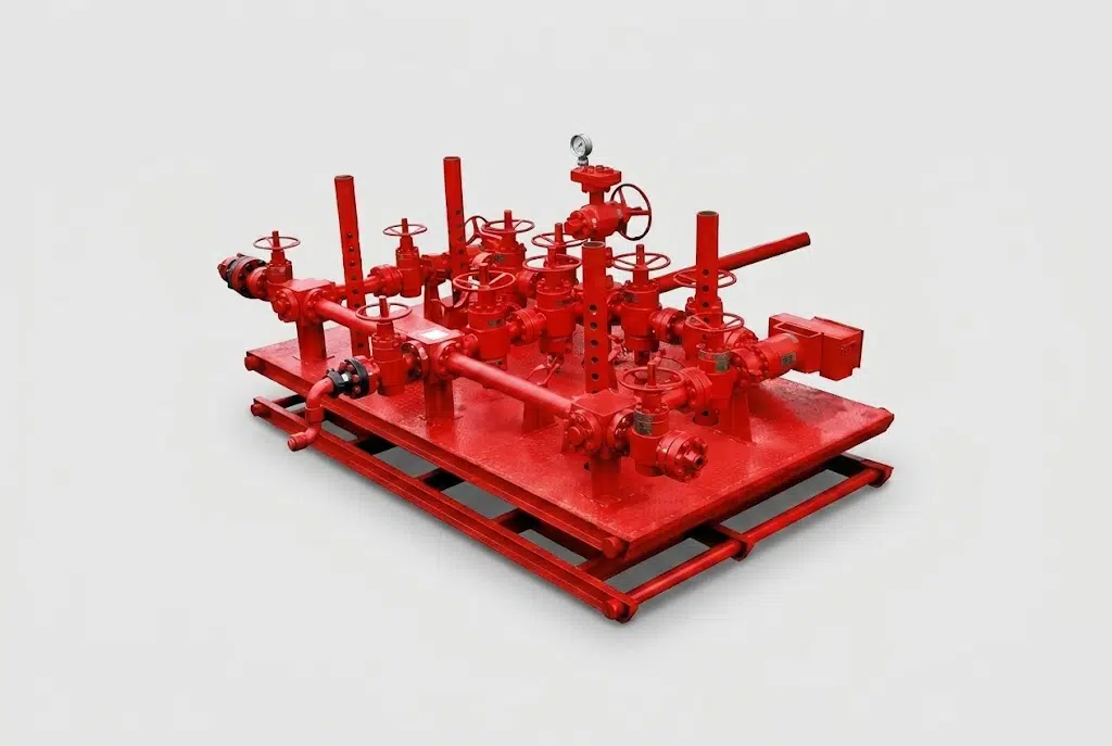
Choke & Kill Manifold | API Spec 16C Well Control System
Choke and kill manifold supply reviewed against the quotation-confirmed responsible manufacturer, component scope, applicable API requirements, order-specific hydrotest pressure, inspection records and delivered documents.
Order-Specific Hydrostatic Test
Quotation-confirmed test scope before shipment
Inspection Scope
Confirmed in the quotation for the selected order
Technical Specifications
2,000–20,000 PSI
WORKING PRESSURE RANGE
2-1/16″–4-1/16″
NOMINAL BORE (MAIN×SIDE)
DD–FF / EE–FF
MATERIAL CLASS
API Spec 6A / 16C
GOVERNING STANDARD
Manual / Hydraulic
ACTUATION OPTIONS
-46°C to 121°C
WORKING TEMPERATURE
PROCESS INSIGHT
When a Well Kicks Back, How a Choke & Kill Manifold Restores Control
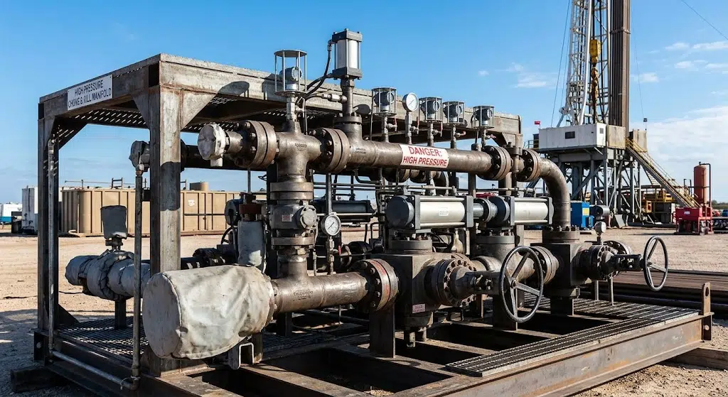
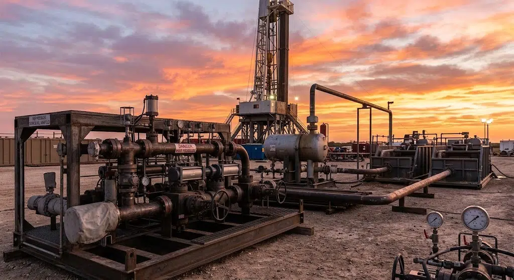
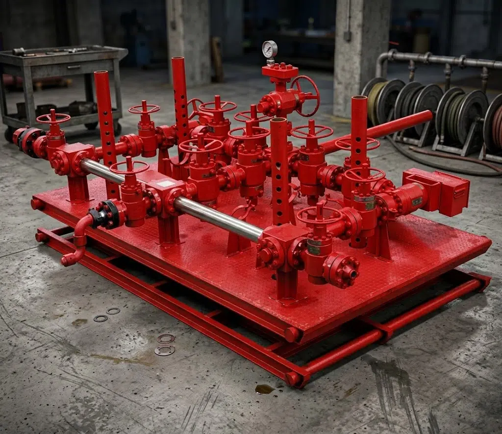
A choke and kill manifold is that one piece of surface wellhead equipment which separates the controlled well from the uncontrolled well and is the key piece of the system in which the bulk of all daily well control technology occurs. When the formation pressure increase to greater than that of the drilling fluid column, gas or liquid is admitted into the wellbore, or a “kick.” A closing of the Blowout Preventer traps the problem, it doesn’t solve it. Without a pathway to bleed off casing pressure and to reestablish the balance, pressure behind a closed BOP will continue to increase.
It’s this function that’s split into two parts in a choke and kill manifold system. Placed on the side outlet of a BOP spool, the choke manifold allow the crew to open and close a set of choke valve to bleed off casing pressure to an open and controlled path via a set of valve and chokes. That open and controlled path allows for the gradual release of casing pressure as well as circulating a kick out via the choke line. Meanwhile, the kill manifold allow the crew to pump kill-weight drilling fluid down the kill line to restore the hydrostatic balance of the well, or in a dire emergency, to bleed pressure directly from wellhead through blow down lines. The choke and kill valve trains can be specified together as one skid-mounted system for the selected well program. Because they’re both functionally and structurally integrated, both are described by the single phrase: choke and kill manifold, although they consist of two completely independent valve trains, built to API Spec 16C. Regulators have studied exactly this kind of equipment reliability question in BSEE-reviewed well control research.
Controlling wellbore pressure once the primary barrier has been breached, and venting the excess pressure to surface, is the function required by every operator for high-pressure well drilling operations, and the choke and kill manifold is the specified method.
FIELD NOTE
Idle Lines Aren’t Automatically Ready
It has been proven that even in the ordinary drilling operation the short piping section between the wellbore outlet and the first valve of a rig’s choke manifold can be plugged by drill solids or barite, thereby plugging the line before any kick even occurred and long before anyone realized that a kick was imminent.1This illustrates another reason that line sizes and valve count and interval of test operation should be more carefully specified in any equipment selection process than it might otherwise appear from many brochures on the market.
ENGINEERING STANDARDS
For the selected choke and kill manifold, confirm the working-pressure basis, inspection scope, and test documentation before purchase.
Give us a quote with your required working-pressure class. We’ll match your rig to the right system.Requirements go up with the scale of the job. A workover or well-testing job pumping at 3,000-5,000 psi won’t require the same manifold design as an HPHT exploration job in the presence of sour gas, but they do both require the same basic discipline – a documented assembly, a hydrostatic test log and a crew that has actually run a choke before it needs to. The drilling engineers reviewing a new manifold for a new program are going to look at three basic elements prior to approval:
- does the working pressure class meet or exceed the planned wellhead pressure?
- Does the material class provide the needed H₂S/CO₂ coverage?
- And is the valve layout – number of chokes, number of gate valves, flow path possibilities – actually providing the crew a viable second path if the main one clogs up or fails?
Welong Choke & Kill Manifold Range, Models & Selection
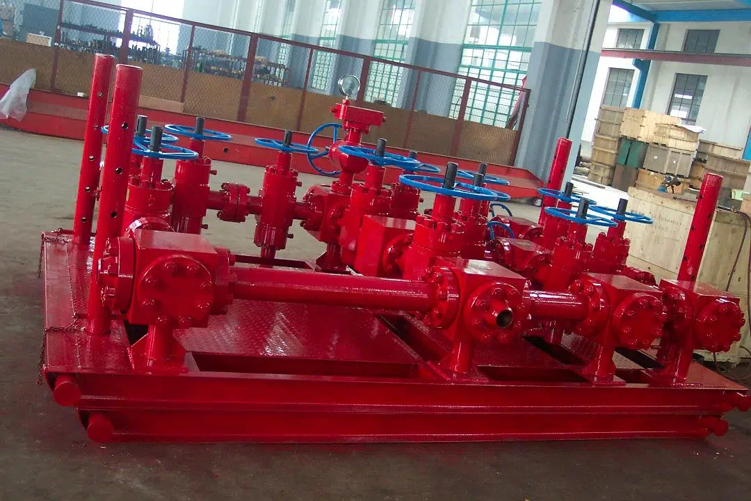
For a JG-series choke manifold or YG-series kill manifold inquiry, the quotation should identify the responsible manufacturer, included choke and gate valves, line pipes, fittings and pressure gauges, applicable API requirements, assembly condition and the records supplied with the order. Do not assume a fixed material or package boundary until it is listed in the quotation.
| Model | JG-35 | JG-70 | JG-105 |
|---|---|---|---|
| Main × Side Path (in / mm) | 3-1/8″×2-1/16″ (80×52) | 4-1/16″×2-9/16″ (103×65) | 4-1/16″×3-1/16″ (103×78) |
| Working Pressure psi (MPa) | 3,000 (21) / 5,000 (35) | 3,000 (21) / 10,000 (70) | 3,000 (21) / 10,000 (70) |
| Working Temperature | -29–121°C (-20–250°F), class P-U | same | same |
| Working Medium | Mud, gas (sulfur-hydrogen / sour service) | same | same |
| Material Grade | DD-FF | DD-FF | DD-FF |
| Model | YG-35 | YG-70 | YG-105 |
|---|---|---|---|
| Main × Side Path (in / mm) | 3-1/8″×2-1/16″ (80×52) | 4-1/16″×2-9/16″ (103×65) | 4-1/16″×3-1/16″ (103×78) |
| Working Pressure psi (MPa) | 5,000 (35) | 10,000 (70) | 15,000 (105) |
| Working Temperature | -29–121°C (-20–250°F), class P-U | same | same |
| Working Medium | Mud, gas (sulfur-hydrogen / sour service) | same | same |
| Material Grade | DD-FF | DD-FF | DD-FF |
The kill-side pressure classes (5,000 / 10,000 / 15,000 psi) increase more quickly than the choke-side classes for a comparable model number. This isn’t just a pricing structure — this indicates kill-side service, pumping heavy fluids into the well against its full pressure, requires a more rugged, higher-spec component than the choke-side bleed-off application, so a matched set of kill and choke manifold has the kill side rated at or above the choke side.
| Well Program Working Pressure | Recommended Choke Model | Recommended Kill Model | Bore (Main×Side) | Material Class |
|---|---|---|---|---|
| ≤3,000–5,000 psi, standard mud service | JG-35 | YG-35 (5,000 psi) | 3-1/8″×2-1/16″ | DD-FF |
| 3,000–10,000 psi, sour service present | JG-70 | YG-70 (10,000 psi) | 4-1/16″×2-9/16″ | DD-FF |
| 10,000–15,000 psi, HPHT / sour | JG-105 | YG-105 (15,000 psi) | 4-1/16″×3-1/16″ | DD-FF |
Spec data: Welong production drawings This table is the base – when deciding final model, you’ve to use your casing program and your mud weight and H₂S exposure to make your decision.
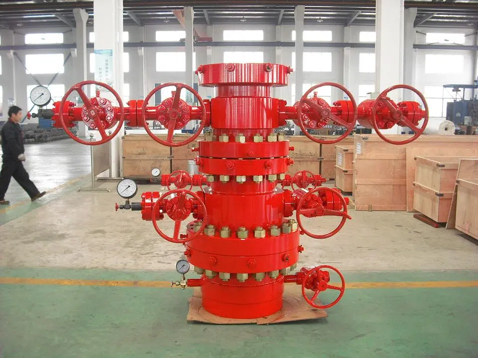
Available in either manual or hydraulically operated forms, the two series are well-rounded packages. Manual choke configurations offer simple BOM and an easier maintenance profile in the field; the JG/YG designs were built with field-replaceable choke manifold parts, built around the same pressure-temperature rating logic used in ASME valve and piping standards, as an intention, not as a post-purchase afterthought.
Its hydraulic version include a remote control panel, allowing for adjustments from a standoff distance rather than standing at the manifold, which is most useful in high-pressure or offshore programs in which exposure to personnel during a kick event is a significant risk. Both series are offered on a fixed or a lifting base; fixed, for rig-floor installation in perpetuity, lifting for programs in which the manifold is transported with the rig. One end of the manifold connects at the BOP spool’s side-flange connection and utilizes field-replaceable components, including those at that point in the train and at other junctures within the valve train, to ensure that routine maintenance never escalates into a total breakdown.
Confirm the selected working-pressure class and H₂S exposure before issuing an RFQ. Provide those requirements in a quote request so the appropriate JG/YG model combination can be reviewed.
This page cover standard drilling programs and a choke manifold well testing job alike. If you require an MPD choke manifold specifically engineered for managed-pressure-drilling service, contact Welong to review configuration details; the demands on a control-panel system and choke response are different than those of conventional well-control setups.
Choke Manifold vs Kill Manifold, How the Two Systems Work Together
The primary purpose of the choke manifold is to regulate bleed-off and divert flow during the circulation out of an influx: it comprises an adjustable choke-valve train supported by a gate valve and a pair of pressure gauges, linked to the choke outlet of the BOP spool, sized against the same ASME pressure-class framework used across the valve train. The purpose of the kill manifold differ; it’s a high-flow injection system designed to force heavier, kill-weight fluid down into the well and restore pressure balance, consisting of a check valve and gate valve train tied into the kill-line and a blow-down function to directly vent wellhead pressure, inject water or deploy fire suppressant if necessary.
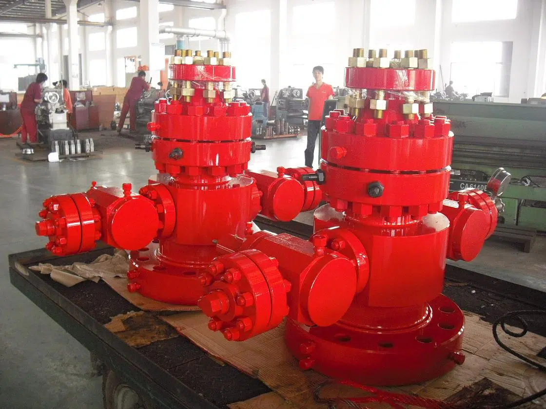
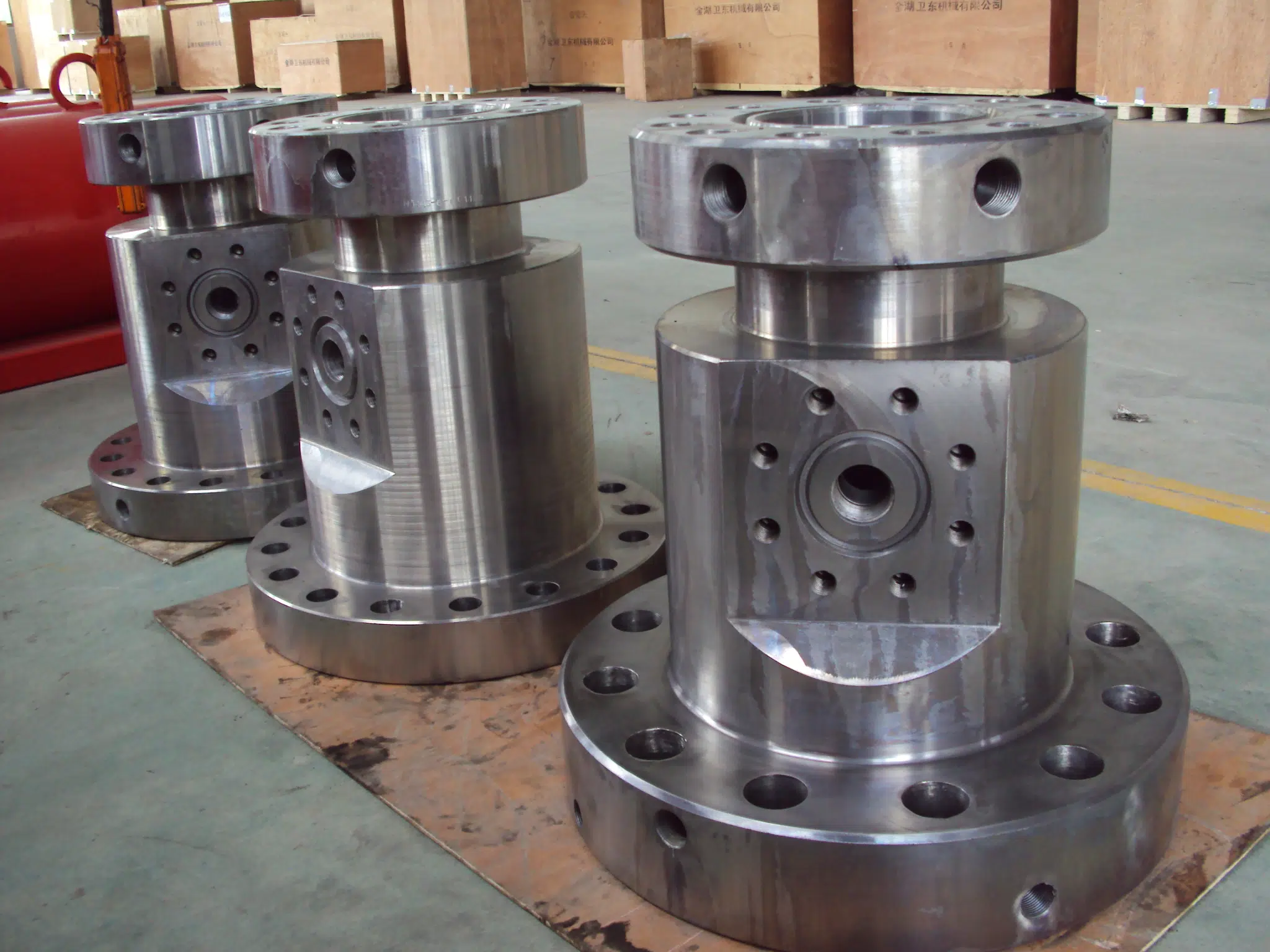
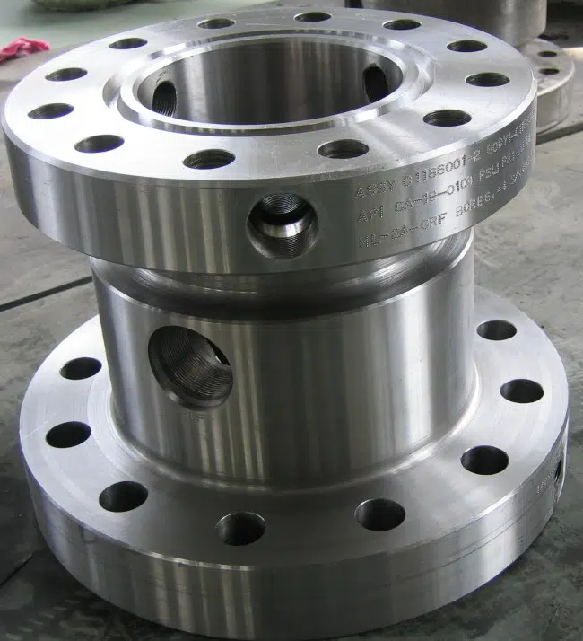
It may seem sensible to use the kill-line as an auxiliary path and rely on the choke-line as the main line for primary flow management. Field experience proves that theory unreliable. In one documented case, a 2-in. line exiting the bradenhead served as the backup to a full-bore choke-line – when the choke-line was blocked, the smaller-bore kill-line ruptured just as rapidly, not more slowly.1
That’s the operational basis on which Welong’s paired choke and kill manifolds have been designed with equivalent or greater kill-side working-pressure ratings than the corresponding choke-side rating rather than sizing the kill manifold to minimize cost. The honest version of a redundancy claim is that both lines have to hold the full working-pressure class, not just the primary, Welong won’t claim a lightweight kill side saves money without compromising the safety margin that redundancy was meant to provide.
For a matched choke and kill pair, confirm the working-pressure class of both lines against the well program. If the required YG configuration is uncertain, request a dual-system review based on the actual kick-tolerance goal.
Daily Operations: If kick is reported on a shallow basis as gas-cut mud or as a gradual rise in pressure the choke side is manned first, circulating at a choked off rate. When a real “kill” operation ensues and we’re to place heavier fluid in the hole the kill side assumes control. Any well kill program that specifies an undersized kill manifold but an adequate choke manifold has prepared only for the shallow scenario.
It’s here also where a hydraulic choke manifold system pays for itself on high pressure jobs: The operator that’s manipulating the choke need the casing pressure, the drill pipe pressure, and the pump rate on the same visual field – getting that information on a remote console, as opposed to having the operator stand right over the manifold during a lively kick, is a difference in safety not a difference in comfort. On a manual system, this coordination come over the radio between the choke operator and the driller – functional, standard on low pressure programs – but there’s some added response time there.
API Spec 16C & Material Class Compliance
A choke or kill manifold order should identify the applicable API requirements, rated working pressure, order-specific hydrostatic test pressure and test records. If an assembly contains components with different rated working pressures, the quotation should state the governing assembly rating and the basis used for the selected configuration.
Material class (DD, EE, FF on the tables above) affects the allowable temperature range and H2S/ sour service suitability according to NACE MR0175 / ISO 15156. If your well programme involves H₂S exposure or sour conditions then the material class cannot be an afterthought in a purchasing box-tick exercise but will dictate which alloys and hardness values are permissible for every part in contact with the fluids in your well. This should be decided before a price is quoted rather than upon arrival at the receiving bay.
Working Pressure Class → Compliance Requirement
| Working Pressure Class | API 16C PSL reference | Material Class (sour service present) | Order Test Pressure and Records |
|---|---|---|---|
| 3,000–5,000 psi | PSL 1–2 | DD | Confirm in quotation and test procedure |
| 5,000–10,000 psi | PSL 2–3 | DD–FF | Confirm in quotation and test procedure |
| 10,000–15,000 psi | PSL 3–4 | EE–FF | Confirm in quotation and test procedure |
The choke-and-kill manifold isn’t a static product – it continues to evolve through engineering and manufacturing development. In fact, some recent patents even introduce new manifold designs, like a 25,000-psi kill-line system for subsea use3 and a new erosion-resistant internal flow design for the choke manifold.4 These have both been filed in recent years, a good indication that manufacturers are continually raising pressure ratings and improving wear resistance for this class of equipment.
Welong Supply and Production Management
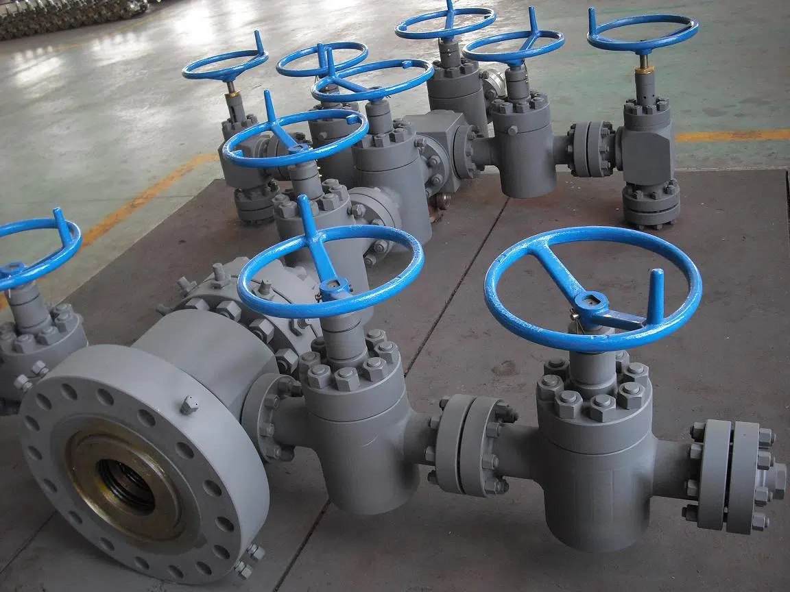
Welong was founded in 2001. For the selected manifold, confirm the documented supplier role, inspection scope, material traceability, and order records before purchase.
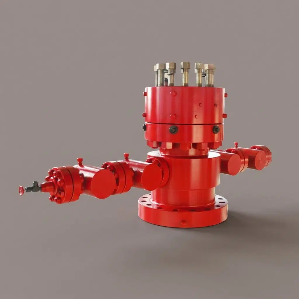
The importance of good post-sales support is always a top priority for procurement teams selecting new equipment vendors. That means while the lowest price on a new choke manifold might be attractive upfront, it’s not necessarily the most cost-effective option if a part breaks or a required certificate is unavailable. A supplier who claims a certification but can’t produce it when a buyer actually asks is a recurring complaint in oilfield procurement, and the gap show up as downtime and added expense.5 The quotation identifies the responsible manufacturer, inspection scope, and available records for the selected item.
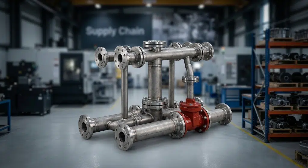
Welong supports procurement teams evaluating a choke manifold supply route. Welong supplies and manages production; the quotation identifies the responsible manufacturer, inspection scope, and available records. Any offer that includes lead times or warranty terms is tailored to the selected configuration and Incoterms.
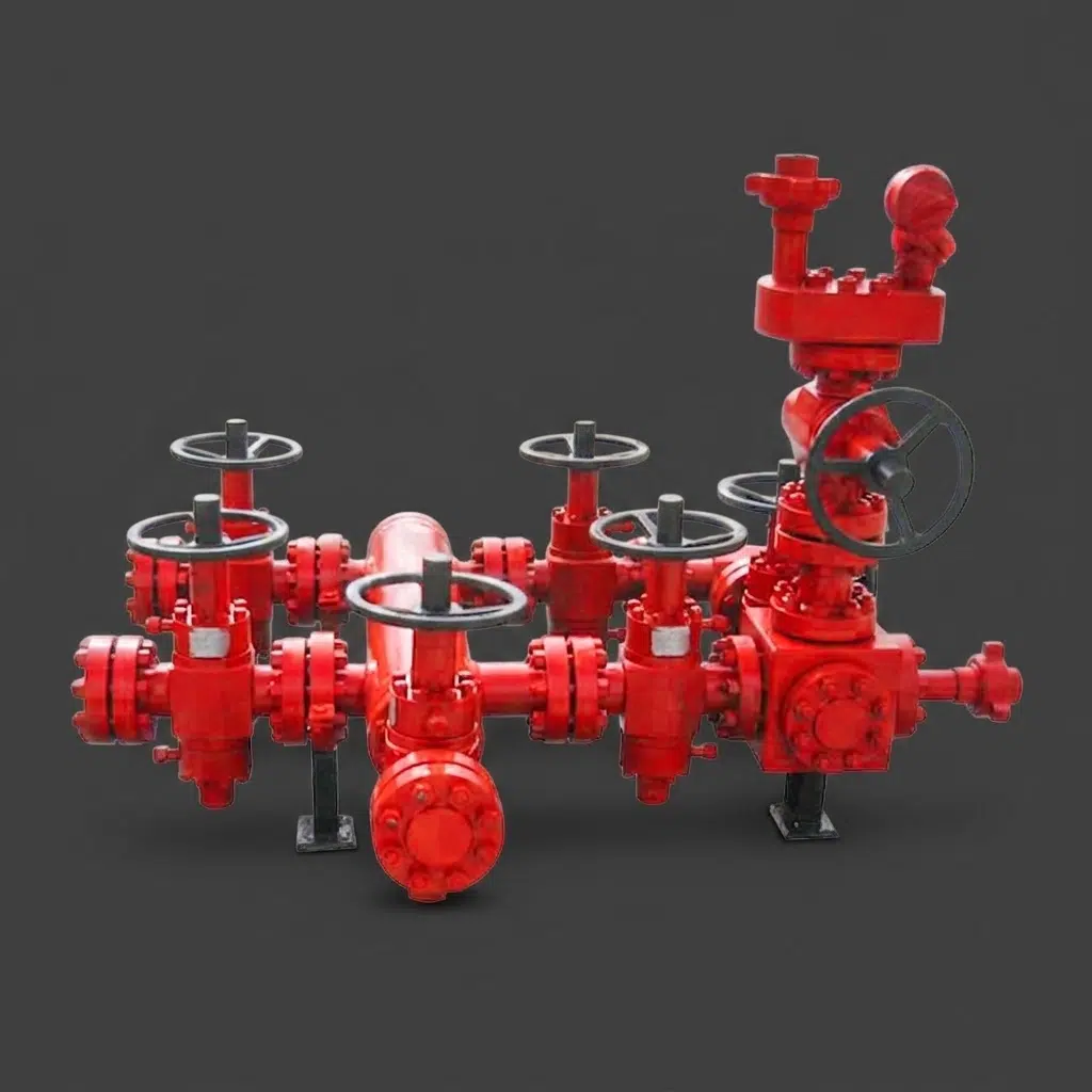
Welong’s core business is to handle supplier development & management and purchasing supervising for international customers from industrial manufacture, oil drilling, aerospace and high-end medical treatment segments. No customer from any of these fields can accept a loose material traceability or an undocumented change in process, this attitude apply to their oilfield tooling division: the same qualification process used for a supplier of aerospace or medical parts will be employed to the supplier of the forged blank and machining of choke/kill manifold bodies. A different client base, the same core question: can you demonstrate the origin and testing standard of this part, and Welong is prepared to demonstrate both.
“The quotation confirms the selected body route, responsible manufacturer, material traceability, and inspection scope for a NACE MR-0175 sour-service order,” he said.
You’re welcome to review our traceability documents – including mill certifications, heat numbers, and pressure test results – on a particular unit prior to placing an order. Our team will help you view those details.
Request a QuoteProcurement Guide, Pricing Logic, Lead Time & Incoterms
The cost of a choke and kill manifold isn’t fixed by an off-the-shelf catalog price, because each different combination of working-pressure class and material class impacts raw materials, wall thickness, and testing on every component exposed to fluid:
-
First are working-pressure class and material class. A 15,000psi EE-FF sour service unit will require a completely different materials bill than a 5,000psi DD-FF unit, even before you begin counting labor, since the underlying ASME material-class framework drives both.
-
Then comes actuation type: manual valves for choke controls vs hydraulic operation of components including remote consoles adds both to the bill of materials and the labor required to test the finished manifold.
-
Third tier is inspection level: third-party inspection may be arranged for selected orders, with provider, scope, and records confirmed in the quotation.
-
Fourth are shipping logistics. Regardless of how we transport the manifold-whether by sea, air or rail under FOB, CIF, DDP, or DDU terms-the costs will vary significantly.
Before You Request a Quote
It will help us significantly if you can advise us of your rig mobilization date as early as possible. Manifold design (especially the actuation type and inspection level) is a key element that determines how the unit is positioned in the build queue, and timely delivery is a consistent deciding factor for many procurement teams, just as important as regulatory compliance documentation.5
In most cases when a customer is looking for the choke manifold price they actually want to know these four aspects, not some catalogue item and that’s why Welong responds with an offer against specification and not price list. Contact Welong to get a precise offer according to your work pressure class, type of operation and required inspections.
Get a lead-time estimate for your well program →
— share your spec and mobilization date, get a build-and-ship timeline back.
Frequently Asked Questions
Choke and kill manifold function comes down to giving the drilling crew a way to control well pressure after a kick; the choke side circulates the influx out through the chokes and bleeding casing pressure, the kill side is used to pump a higher weight fluid down the wellbore to establish a balance.
This provides the function to restrict flow, limit pressure on the return side by choke valves that are adjustable, then kill the well on the injection side through the kill manifold. A kill manifold is a train of check valve and gate valve with kill-weight fluid injection to the wellbore. Kill and choke manifolds were designed to operate as a unit, though they manage separate parts of a well control scenario.
The choke line: Running from the BOP stack to the choke manifold and is the path for the incoming influx that’s being circulated out under a controlled pressure. The kill line: running from the kill manifold to the BOP stack and is the line for kill-weight fluid that’s being pumped into the well.
Mounted close to the BOP stack it’s connected to a side port outlet of the BOP spool and placed to allow for easy access and operation by the driller or rig crew when the need arises to operate during a well control event, generally on the skid with the rig substructure or on a special manifold trailer for a mobile rig.
It should meet or exceed the max predicted wellhead pressure in your well program. It’s generally expected to be from 2,000-20,000 psi across the industry. You should choose a model using the expected working pressure, not just surface casing pressure rating from your well program.
A hydraulic choke operated by a remotely-controlled hydraulic control panel permits an operator to vary pressure from a safe standoff distance and react quicker to a kick. While manually operated chokes can be cheaper and will suffice for lower-pressure and lower-risk well programs, more pressure and offshore programs demand hydraulic actuation.
Sour Service – NACE MR0175/ISO 15156 class of materials should be used – on Welong’s JG/YG range this usually is the DD-FF or EE-FF classes detailed in the spec tables above. Ensure you verify your H₂S partial pressure and CO₂ concentration with your well engineer prior to selection.
Yes – the quotation can confirm bore size, working-pressure class, actuation type, and base style for the selected configuration rather than relying on a fixed catalogue unit.
Inspection scope and records are confirmed in the quotation. For selected orders, third-party inspection may be arranged; the provider, scope, and records are confirmed in the quotation.
Choke & Kill Manifold Source-Backed Specification Rows
| Parameter | Current source wording |
|---|---|
| JG-35 well-program selection | ≤3,000–5,000 psi, standard mud service JG-35 YG-35 (5,000 psi) 3-1/8″×2-1/16″ DD-FF |
| JG-70 well-program selection | 3,000–10,000 psi, sour service present JG-70 YG-70 (10,000 psi) 4-1/16″×2-9/16″ DD-FF |
| JG-105 well-program selection | 10,000–15,000 psi, HPHT / sour JG-105 YG-105 (15,000 psi) 4-1/16″×3-1/16″ DD-FF |
| 3,000–5,000 psi order test scope | 3,000–5,000 psi working-pressure class; confirm order-specific test pressure and records in the quotation and test procedure. |
| 5,000–10,000 psi order test scope | 5,000–10,000 psi working-pressure class; confirm order-specific test pressure and records in the quotation and test procedure. |
| 10,000–15,000 psi order test scope | 10,000–15,000 psi working-pressure class; confirm order-specific test pressure and records in the quotation and test procedure. |
Procurement & Capability
Choke & Kill Manifold Capability Review
China Welong reviews the buyer drawing, product specification and inspection scope before quotation.
This review is scoped to the Choke & Kill Manifold configurations set out in the specification table on this page — 6 documented rows covering Parameter, Current source wording, JG-35 well-program selection and JG-70 well-program selection.
24 hEngineer-reviewed quotation on business days
2001Founded in 2001
30+30+ engineers on staff
5 yrStamped serial traceability
Quotation Scope and Commercial Terms
Pricing is prepared against the selected product configuration, material route, inspection scope and shipment terms.
- Quotes are returned within 24 hours on business days, reviewed by an engineer.
- T/T or L/C by wire transfer.
- We ship EXW, FOB, CFR or CIF; other Incoterms on request.
- We work from 2D drawings and 3D CAD models (AutoCAD, Pro/ENGINEER, SolidWorks; .dwg and .igs).
Production Planning
Production timing is confirmed with the quotation after quantity, process route and finishing scope are reviewed.
- We hold agreed items in stock and ship against your release to shorten delivery. Feasibility is confirmed at drawing review.
- Manufacturing at Xi'an, Shaanxi and at Jiyuan, Henan.
- 0.01 mm machining precision.
- Material standards to ISO, BS, ASTM, ASME, DIN, JIS and GB.
- Orders ship in standard export wooden cases, or the packing you specify.
Order Review and Responsibility
The responsible manufacturer, inspection scope and document package are identified for the selected item.
- The quotation records whether the item is made in our own works or by an approved supplier and confirms the responsible manufacturer and inspection scope.
- Production-management review is re-audited every two years; the quotation confirms the responsible manufacturer and inspection scope for the selected item.
- Forgings from 0.2 to 50 tons.
Current Product Specification Evidence
These product-scoped numeric rows reproduce current-page wording. The quotation confirms the responsible manufacturer and inspection scope for the selected item.
- Each piece carries a stamped serial number and stays traceable for five years to its chemical composition, mechanical properties and measurement report, with the test coupon retained.
- An EN 10204-3.1B material certificate with chemical composition and mechanical properties, a dimensional measurement report, and UT and MT reports ship with your order.
- Inspection is by coordinate measuring machine, ultrasonic, magnetic particle and X-ray.
| Parameter | Current source wording |
|---|---|
| JG model set | Model JG-35 JG-70 JG-105 |
| JG main and side paths | Main × Side Path (in / mm) 3-1/8″×2-1/16″ (80×52) 4-1/16″×2-9/16″ (103×65) 4-1/16″×3-1/16″ (103×78) |
| JG working pressures | Working Pressure psi (MPa) 3,000 (21) / 5,000 (35) 3,000 (21) / 10,000 (70) 3,000 (21) / 10,000 (70) |
| JG working temperature | Working Temperature -29–121°C (-20–250°F), class P-U same same |
| YG model set | Model YG-35 YG-70 YG-105 |
| YG working pressures | Working Pressure psi (MPa) 5,000 (35) 10,000 (70) 15,000 (105) |
Request a Product Review
Send the drawing, product specification and inspection requirements for a quotation review.
![Choke & Kill Hose: [Field Guide]](https://welongoiltools.com/wp-content/uploads/2026/07/choke-kill-hose-guide-featured-1-150x150.png)