Get in touch with Welong Company
Bucking Unit Guide: 9 Functions, Types and Torque

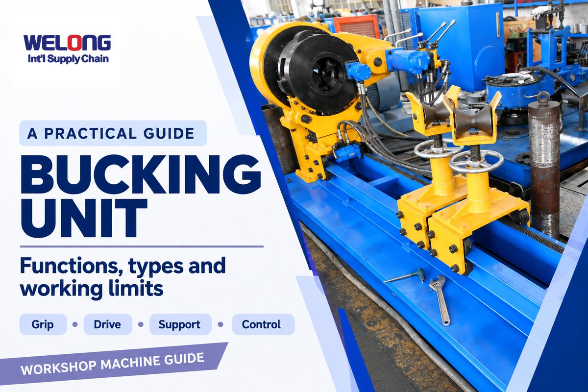
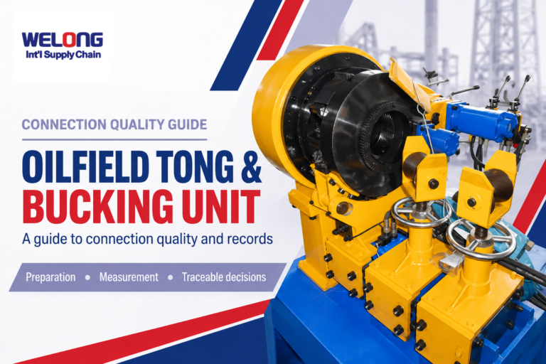
A Bucking Unit is an oilfield machine that tightens or loosens threaded connections. It uses powered grips to rotate one element while the other is held against the force by a backup grip. Finishing the job requires correct positioning, appropriate surfaces and a make-up procedure specific to the connection.
By Cherry · Updated October 2026
Other uses of the same basic machine include the assembly of tubing couplings, disconnecting of service tool housings and preparation of tubular stands. Layout of the controls changes based on the task. Therefore, more maximum torque doesn’t automatically mean more finished work.
What Does a Bucking Unit Do?
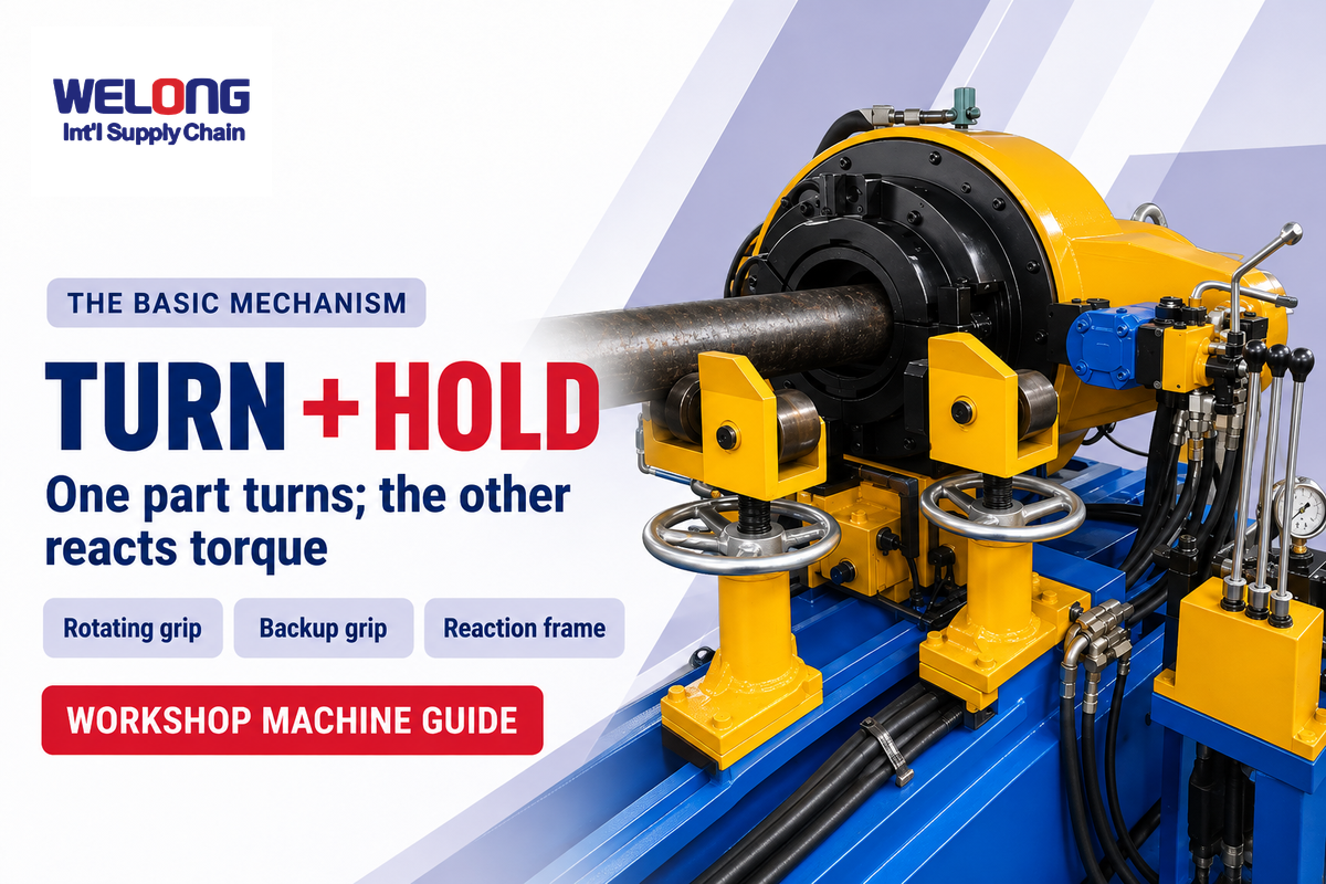
An oilfield bucking unit is used to make up and break out threaded connections through controlled relative rotation, using powered grips and a frame that reacts torque. A thread (fit) is required for the coupling and/or separation of the components. Thread cutting and thread inspection are separate processes from coupling and/or separation of the components.
Holding a jar steady while turning its lid to separate it illustrates the opposing-grip principle. A hydraulic bucking unit performs the function for tools and pipe with powered jaws and a frame designed to absorb loads.
During makeup, the screw connection is made and the required torque is applied. During break-out, the screw connection is reversed to disconnect the components. The torque required to release a connection may be different from the torque required during its makeup. The machine rating and the workpiece’s allowable loads are two separate limits.
Bucking units play a supporting role in oil and gas drilling by setting up equipment at service bases and other places. They’re torque machines, not drilling motors working downhole. Welong’s bucking unit solution covers commercial machine options; this manual discusses their mechanisms.
Inside the Machine: Nine Functions Behind the Torque
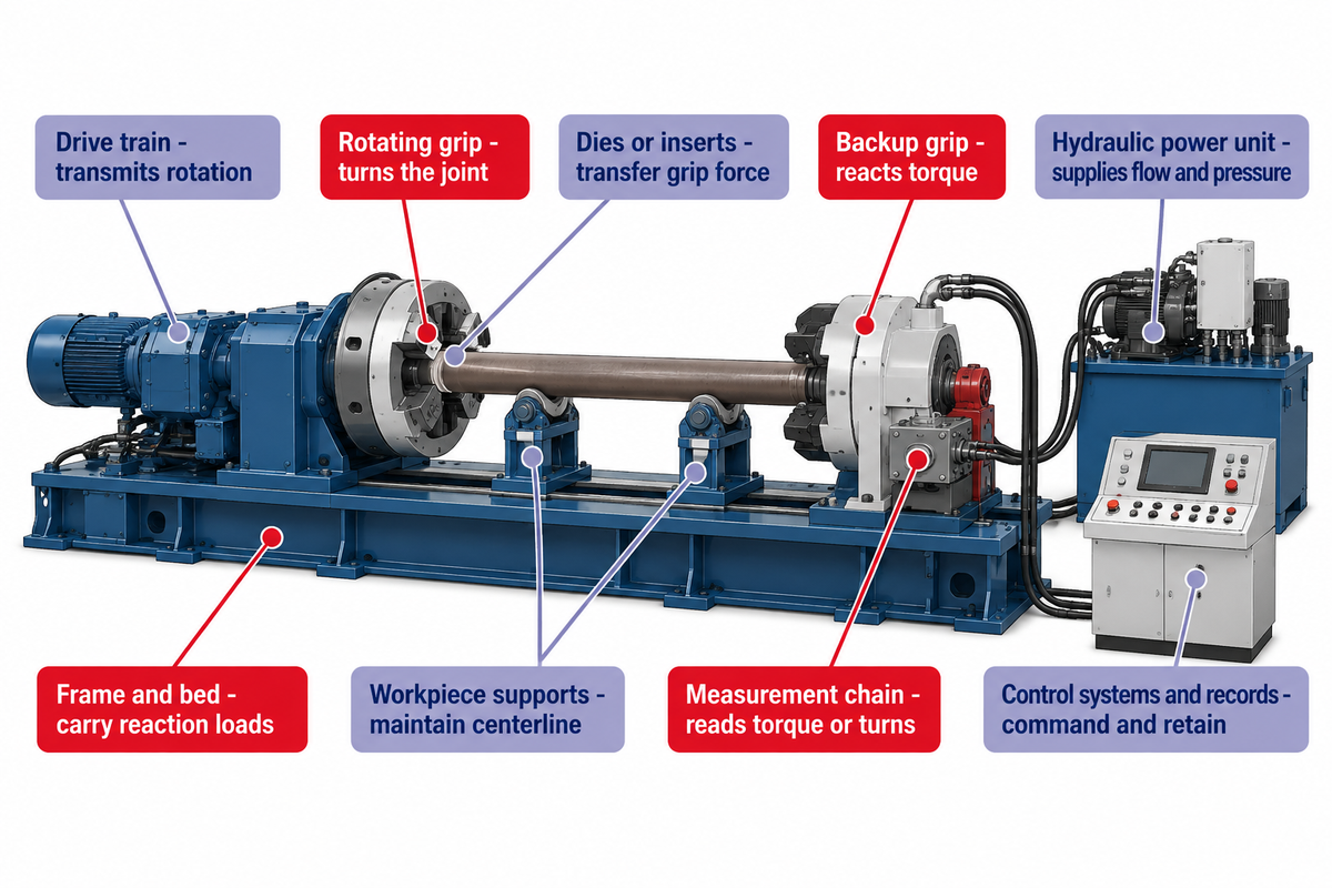
A bucking unit consists of a head interacting with a support to drive and control a function. The rotating head provides motion, and the backup provides the reaction. Frame and supports position the work. The hydraulic system provides the power. Torque sensing, and automatic cutoff and data logging, require their own defined equipment scope.
A workshop lead will trace the information and force paths through a machine by following the instructions for nine functions shown on the table. Several functions may share one assembly. A tailstock (support) may combine backup gripping, axial movement and alignment. A separate power unit may be placed outside the main frame.
| Function | What it does | What the workshop needs to distinguish |
|---|---|---|
| Rotating grip | Turns one side of the threaded joint | Continuous rotation versus a limited angular working stroke |
| Backup grip | Holds the mating component against torque | Accessible gripping length and reaction arrangement |
| Dies or inserts | Transfer gripping force into the workpiece | Contact geometry, material and permissible surface marks |
| Frame and bed | Carry reaction loads and locate the heads | Fixed, travelling or otherwise adjustable head spacing |
| Workpiece supports | Carry weight and maintain the intended centerline | Short heavy tools versus long tubulars |
| Drive train | Transmits motor rotation to the gripping head | Available torque and speed in each operating stage |
| Hydraulic power unit | Supplies fluid flow and pressure | Motor, pump, tank, cooling and installation scope |
| Measurement chain | Converts sensor signals into torque or turn readings | Working range, calibration and result uncertainty |
| Control systems and records | Command motion and retain job information | Manual control, automatic cutoff and optional reporting |
Fluid power is converted to rotation by a hydraulic motor. A valve directs the flow; cylinders may close a clamp or move a support. Advanced hydraulic systems may add proportional control; sensing and recording require their own equipment. The HPU (hydraulic power unit) supplies fluid power; its electric motor rating is a different quantity from a controller’s electrical consumption.
A torque log stores a measured signal. It doesn’t replace suitable dies, stable support or the connection procedure. Controls can’t ensure acceptable threaded connections when the workpiece enters the grips at the wrong angle or contact surfaces are unsuitable.
Bucking Unit Types: Separate Motion, Layout and Automation
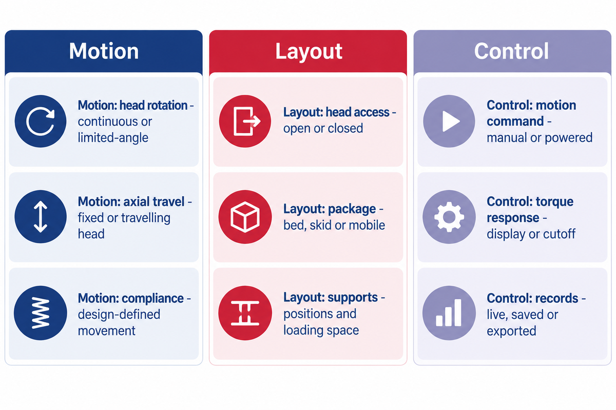
Aspects of a bucking machine can be seen in continuous rotation, short stroke, mobile and automatic features. These should be considered separately. A machine can combine continuous rotation with a manufacturer’s short-stroke design, and a mobile package can use manual controls or add torque monitoring. The label doesn’t always give the full picture of the build.
3-Axis Bucking Unit Decoder
The 3-Axis Bucking Unit Decoder separates motion, layout and controls when identifying equipment. Overlapping machine features are described on equipment labels.
| Axis | Describe these separately | Why it changes the job |
|---|---|---|
| Motion: head rotation | Continuous revolutions or limited-angle action | Shows whether the drive needs a reset between angular strokes |
| Motion: axial travel | Fixed or travelling head position | Shows how the machine accommodates assembly length |
| Motion: compliance | Movement allowed by the selected head and backup design | Separates controlled movement from an assumed rigid arrangement |
| Layout: head access | Open or closed gripping head | Changes the route by which a workpiece enters |
| Layout: package | Stationary bed, skid or mobile package | Changes transport and installation tasks |
| Layout: supports | Support positions and available loading space | Accommodates the workpiece beyond its gripping diameter |
| Control: motion command | Manual valves or powered positioning controls | Defines which movements the operator commands |
| Control: torque response | Displayed torque or an included automatic cutoff function | Separates measurement from automatic stopping |
| Control: records | Live display, saved readings or exported job reports | Defines what information remains after the assembly leaves |
McCoy Global’s “Continuous Short Stroke” product category describes adjustable distance between tongs, and “short stroke” doesn’t always describe the opposite of continuous rotation. Fully rotational describes complete revolutions of the head; 360° rotation doesn’t specify loading access. The drawing of the selected manufacturer describes the movement.
What is a mobile bucking unit?
A mobile bucking unit is a make-up and breakout package arranged for relocation between suitable work locations. Mobility describes the package and transport arrangement. It doesn’t describe the degree of automation or torque, or if the package is ready to operate as soon as it arrives at its destination. Supports, power, lifting means, access and the operating area still belong to the installation plan.
A skid-mounted unit can remain stationary throughout a job. A trailer package may need additional support. For the different question of choosing between rig-floor tongs and a workshop system, see the rig-floor access and workshop layout trade-offs.
Torque, Speed and Size: Read the Working Envelope
The usable working envelope takes into account torque range, rotational speed, gripping diameter, through-bore clearance, and head spacing. Maximum torque is one limit. The lowest calibrated torque, the available speed at the required load and the space around the connection can be just as important for a small or awkward assembly.
Welong’s WL178-20 specifications list a 60.33–177.8 mm outside-diameter range, 20 kN·m maximum makeup torque and a 260 mm bore. These model-specific values describe different dimensions of fit and capacity. A workpiece passing through the bore also needs a suitable gripping diameter and adequate contact length at each head.
Mechanical power at a stated torque and speed
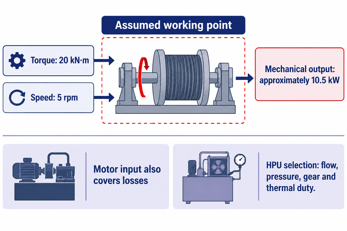
Assumed inputs: I’m assuming the head delivers 20 kN·m while rotating at 5 rpm. From equation 10.31 of OpenStax University Physics, we get:
P = T × ω = T × 2πn ÷ 60
20,000 N·m × 2π × 5 ÷ 60 = 10,472 W, or approximately 10.5 kW of mechanical output.
This calculation describes one assumed working point. Motor input must also cover losses and the rest of the hydraulic duty. Selecting an HPU requires the machine’s flow, pressure, gear and thermal-duty data. Multiplying a catalogue’s maximum torque by its maximum speed can pair values that belong to different operating stages.
Torque values need units, such as kN·m or ft-lb, and a measuring chain with a working range and uncertainty suited to the required decision. Measurement precision is separate from the choice of unit. Under NIST’s metrological traceability guidance, traceability belongs to a measurement result and doesn’t alone establish fitness for purpose.
Can the bucking unit be customized for our OD and torque range?
A bucking unit can be configured to the desired OD and torque range when the supplier gives the appropriate heads, drive and tooling. The review should also cover through-bore clearance, minimum gripping length, head spacing and workpiece support. A larger torque rating on its own won’t make an unsuitable housing or short connection fit the machine.
Welong’s bucking unit model selector provides a starting point for matching published model ranges. Short tools and unusually shaped assemblies need their geometry considered alongside those ranges.
Where Bucking Units Fit in Tubular and Tool Work
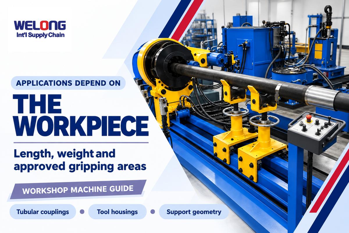
Bucking units are designed for assembly and disassembly of threaded oilfield components. Applications in oilfield operations include tubing and casing couplings, drill-related tubulars and completion-tool subassemblies. The important factors are the length of the workpiece and how the weight is distributed, and the approved gripping areas. Based on this, the machine can hold and support the workpiece with a suitable arrangement.
Permanent and remote locations can prepare double and triple stands and subassemble downhole equipment as described in Aaron Sinnott’s JPT account of offline tubular handling. Preparation hub tasks can be very different from casing operations on the rig.
An Illustrative tubing job: a shop receives a batch of matching pipe and couplings. The repeatable joint geometry means that the shop can load in a repeatable manner. Still, the shop lead has to bring each joint onto the centerline and leave room for the completed length. A faster rotating head adds little if the pipe waiting to be loaded is waiting for a shared crane. The comparison is between complete work cells: the machine, incoming rack, supports, and the exit path. A quoted rate for rotation does not include all work to load and unload the complete work cell.
Illustrative tool-service job: a short housing arrives beside a longer motor assembly. Both may sit within the nominal torque range, yet the short part offers less room between its gripping areas. An offset body also alters where supports can contact it. The first challenge for the technician is to position the work securely so it does not grip a sealing surface or load a sensitive area. Drill collars and downhole mud motors illustrate why product geometry belongs in that discussion.
Gripping marks on damage-sensitive materials affect both holding and quality.
Permissible markings on pipe bodies depend on the material and applicable limits; details of tubular connection preparation are given in Scott Sivewright’s technical report.
From Loading to Unloading: What Sets Cycle Time?
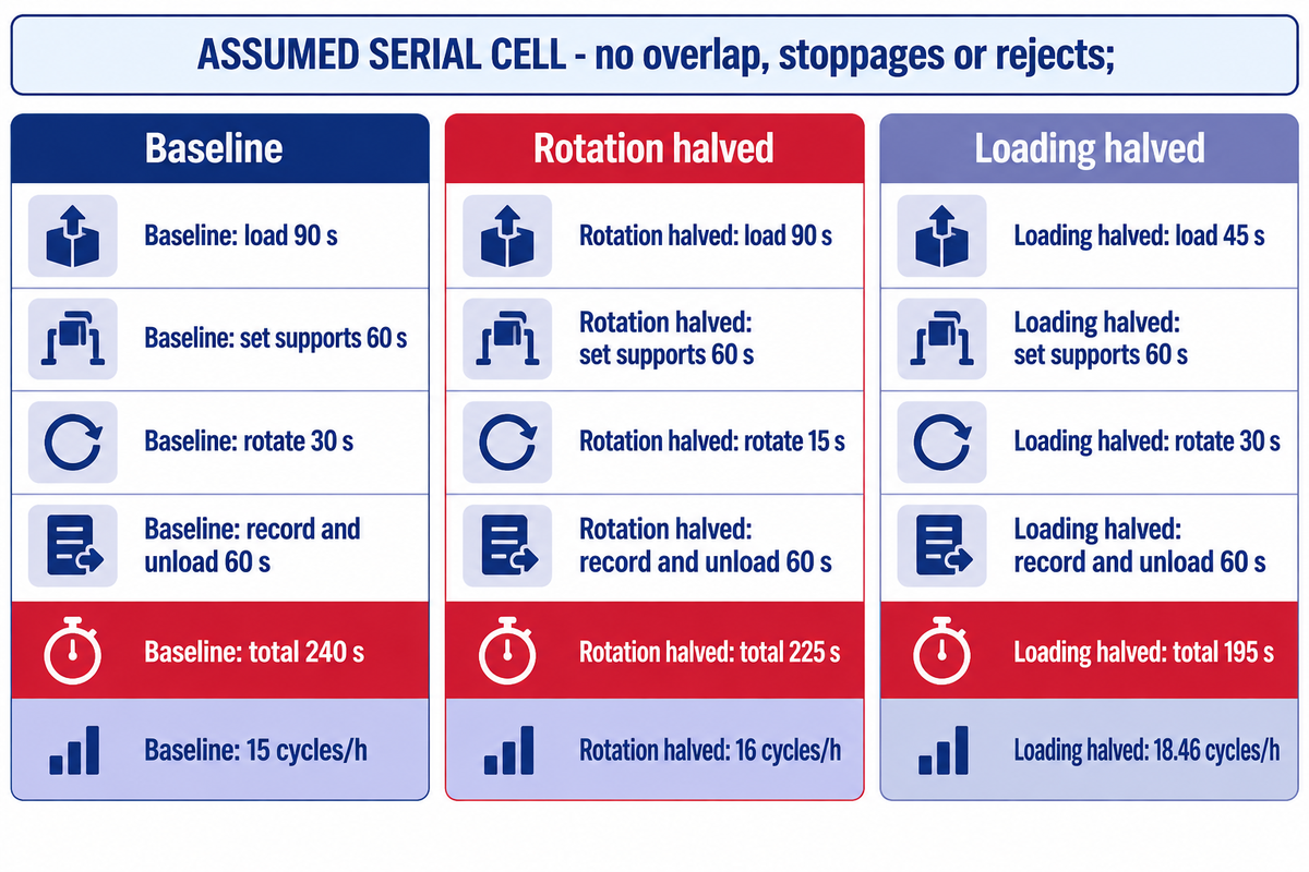
Taking into account all variables, the time needed to load, position, rotate, release and unload the connection makes up the work-cell cycle. Reducing the time spent rotating provides benefit only to that part of the cycle. Faster rotation increases productivity only if it speeds up the total cycle and the rest of the work cell keeps pace.
A signed Offshore account of an integrated bucking system describes conveyors, support rollers, and exit racks around an open-head machine. Those interfaces describe why a head-speed comparison overlooks part of the time required. For efficiency and safety, the planned loading route has to avoid putting people in the work area.
Assumed example: One serial work cell, one product family, no overlapping actions, breaks, stoppages, or rejected joints. Compare changing only the rotation stage with changing only loading:
| Stage | Baseline | Rotation time halved | Loading time halved |
|---|---|---|---|
| Load and position | 90 s | 90 s | 45 s |
| Set supports and clamp | 60 s | 60 s | 60 s |
| Rotate the connection | 30 s | 15 s | 30 s |
| Record, release and unload | 60 s | 60 s | 60 s |
| Total serial cycle | 240 s | 225 s | 195 s |
| Calculated uninterrupted capacity | 15 cycles/h | 16 cycles/h | 18.46 cycles/h |
The formula is 3600 seconds in an hour divided by total seconds in a cycle. Using this formula, we can see where loading improvement will save the most cell time. The results show possible capacity limits, not predicted actual output for a shift. Breaks, changing dies, mixed tools, and rework, or a combination of the above, determine what the shift actually achieves.
Throughput and bottlenecks, especially with mixed product, are covered in research carried out by NIST on multi-job production systems. When doing scheduling or sequencing, you should attempt to reflect the job mix as close to reality as possible. Don’t extend one demo to a complete shift.
Maintenance and Common Bucking Unit Problems
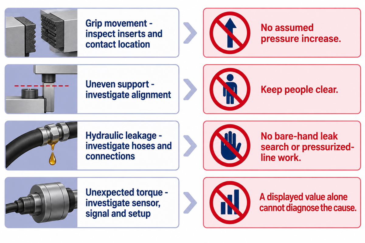
Planned maintenance is carried out as per the installed machine’s manual and operating conditions. Routine checks are carried out on gripping inserts, supports, hydraulic components, sensors, and controls. If there’s unusual movement, leakage or inconsistent readings, work is stopped and the cause is investigated using the approved machine procedure. Components that have been affected are inspected as per the procedure.
Why is regular maintenance important for Bucking Units?
Service plans for bucking units include regular maintenance because wear and tear can adjust gripping, alignment and hydraulic response. A machine that still turns can have worn inserts or an unreliable measuring chain. Planned inspection can detect those changes and prevent damage to the workpiece or downtime.
Maintenance schedules require the manufacturer’s intervals, available service materials and limits. Cleaning needs and equipment workload affect routine service demands, so durability and lifespan may vary with operating conditions. New operators also need to identify which checks are for operation and which are for authorized maintenance.
| Observed issue | System to investigate under the manual | Boundary |
|---|---|---|
| Movement inside a grip | Insert condition, contact location and approved clamping setup | Do not compensate with an assumed higher pressure |
| Uneven support or unexpected movement | Workpiece support and machine alignment | Keep people clear while the job is made stable |
| Hydraulic leakage or abnormal response | Hoses, connections, fluid condition and drive components | No leak searching with bare hands or work on pressurized lines |
| Unexpected torque readings | Sensor, signal path, calibration scope and setup | A displayed value alone cannot diagnose the cause |
Normal operation also needs protection around moving grips, rotating work and loading areas. For a US general-industry workshop, 29 CFR 1910.212 addresses machine guarding. Hand tools used for loading supplement required guarding; they don’t replace it.
“Push buttons, selector switches and other control circuit type devices are not energy isolating devices.”
OSHA, 29 CFR 1910.147(b), energy-isolating-device definition
The applicable energy control procedure needs to cover stored hydraulic and mechanical energy during servicing. The OSHA 1910.147 standard explicitly excludes the oil and gas well drilling and servicing. Thus field work requires the rules and site procedures be considered separately. An emergency stop doesn’t replace maintenance isolation.
Bucking Unit Cost, Rental and Supplier Choices
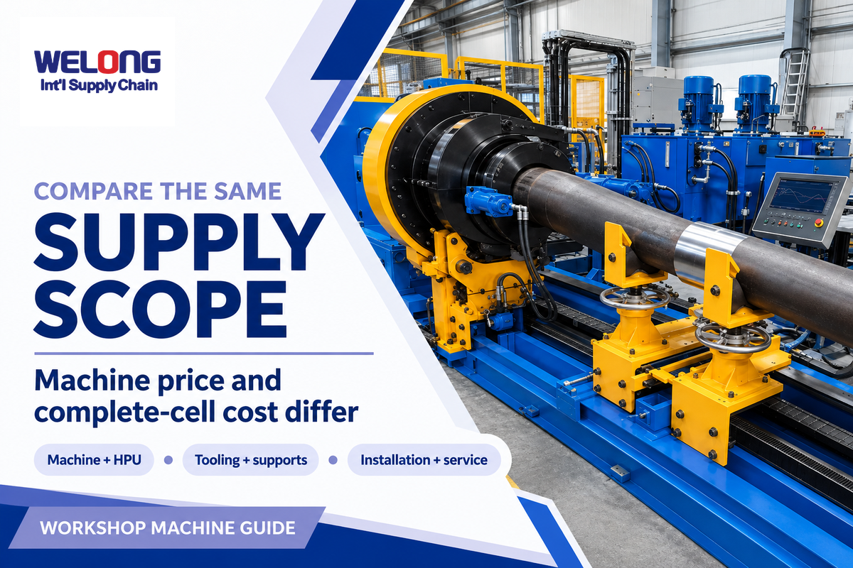
Define whether the equipment scope of a bucking-unit price includes the machine, HPU, gripping sets, support structure, measuring system, installation and servicing. A bare machine, a used package and a commissioned work cell have different scopes and prices. Consider the same included equipment and duty before making a purchase versus renting or contracting makeup and breakout services.
A hydraulic breakout package may seem customizable around the work, but each added function changes the commercial comparison. Procurement needs a scope list showing who will manufacture the equipment, who supplies the controls, and who performs commissioning and replacement of parts. A supply-chain partner, a machine manufacturer and an operating-service provider can play different roles in the oil and gas industry.
The rent-versus-buy method: compare total quoted rental charges for the expected chargeable period with the purchase, setup and ownership costs, less expected resale value. Add transport and recurring mobilization on the side that incurs them. Include support and tooling on both sides. The outcome differs when a short job still attracts a minimum rental period.
Illustrative purchasing decision: A workshop has a short tubing campaign followed by uncertain work. They rent or contract out during the campaign to limit their commitment. A service hub with repeated, compatible work does things differently: It can distribute setup and tooling costs across multiple campaigns. Before the purchase, the workshop lead does a timing comparison to determine if handling or machine time or job changeover limits throughput. The quality lead defines the limiting measurement and gripping scope. The cost owner compares quotes on the same basis. The outcome determines the purchasing decision.
For a quote, provide the actual OD range, smallest gripping areas, assembly lengths and weights, required makeup/breakout torque, thread families, working hours and reporting requirements. Send power supply, floor layout and lifting access. Send us the job envelope through Welong’s equipment inquiry so that the proposed machine and support package may be discussed.
Workshop Integration and What Is Changing
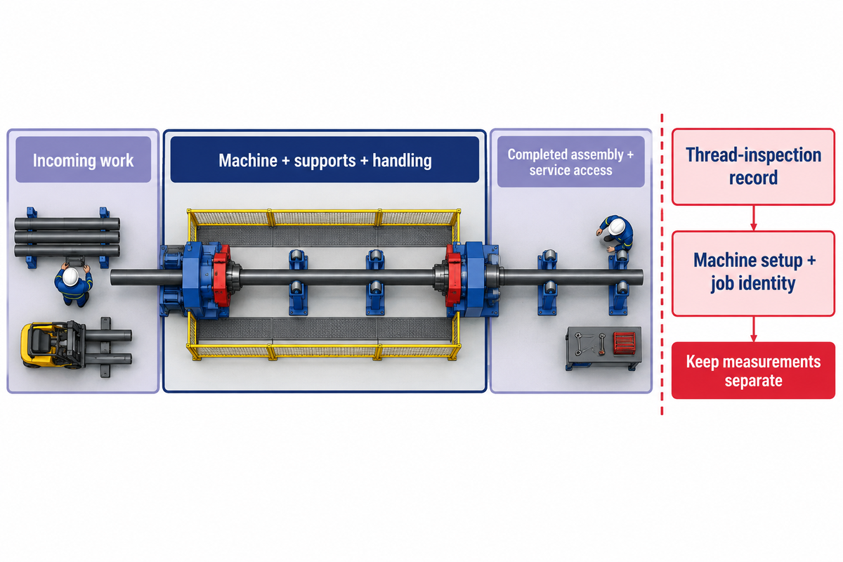
The connection between the bucking unit and the next lifting, support and assembly tasks is planned at workshop installation. Recent changes in thread inspection have affected this handoff. API announced the seventeenth edition of Specification 5B in October 2026, with provisions for validating newer thread-measurement methods and clearer calibration and recordkeeping expectations.
Joint makeup judgment follows the connection owner’s applicable procedure. The API Announcement of October 7, 2026 states that when results from alternative measurement technologies are disputed, “traditional mechanical gauging” governs acceptance or rejection. The contactless measurement provisions concern thread manufacturing and inspection. Joint makeup and connection owner’s applicable procedures govern torque and sealing.
Retain the thread-inspection record, machine setup and job identity together while keeping their measurements separate. References to API or ISO apply within their stated product or system scope. A reference alone does not certify the machine bearing it.
During physical installation, account for incoming work, service access and the completed assembly. Match the centerline of the machine to its supports and handling equipment. Fixed location equipment requires an appropriate anchoring arrangement. Portable equipment design changes the means to transport the equipment. It doesn’t alleviate other installation activities.
Bucking Unit FAQ
Can the machine handle CRA, chrome, or damage-sensitive pipe?
View Answer
Damage-sensitive pipe requires gripping and support suited to its material and permitted surface condition. Insert material, contact area, clamp force and handling determine that suitability. A non-marking description must match the actual job requirements. Keep sealing surfaces and unsuitable gripping areas out of contact, and use the connection or pipe owner’s applicable limits.
Is final torque enough to judge connection quality?
View Answer
Final torque is one part of a connection-specific acceptance decision. The required process can also consider turns, shoulder behavior, preparation and other criteria set by the connection owner. A machine reaching its target torque doesn’t by itself resolve those requirements. Welong’s oilfield tong and bucking unit connection-quality guide covers that separate task in more detail.
Is this bucking unit suitable for premium connections?
View Answer
Premium connections require working torque and speed, gripping surfaces, alignment, sensing and retained records that meet the connection owner’s procedure. Premium isn’t a single thread geometry or one universal torque window. Include those requirements in the equipment and process review before assembly. The selected control package also needs to retain the job information that procedure requires.
What common issues arise from inadequate training for operators?
View Answer
Wrong tooling, poor support and an incorrect approach to moving work can arise from inadequate training. Job-program selection is another point where human error can enter. Training needs the installed machine and its site procedure.
How does a clean environment affect Bucking Units?
View Answer
Clean work areas help keep debris away from gripping surfaces, exposed threads and hydraulic service points. Housekeeping also leaves the loading route and controls accessible. Contamination at a thread or sealing surface can affect the connection independently of the machine’s torque setting. Cleaning methods and fluid-service practices need to follow the installed equipment and connection instructions, including energy isolation where the activity requires it. More pressure or a different torque setting isn’t a substitute for dealing with contamination.
How do I confirm a bucking unit is ready for production before final payment?
View Answer
Demonstrate the required workpiece envelope, controls, measurement functions, records and handover items against the agreed purchase scope and acceptance plan. Include installation and commissioning responsibilities. Reaching one torque value tests only part of the complete production task.
How does the hydraulic system benefit the Bucking Unit?
View Answer
Hydraulics transmit power to the rotating drive and can operate the grips and supports. Valves direct the flow, while the installed control arrangement governs how movements are commanded. That makes powered clamping and rotation possible within the machine’s rated design. Torque control, repeatability and recording still depend on the complete drive, sensing and control package. High torque and high pressure describe different physical quantities. Neither alone measures connection quality, and a hydraulic drive doesn’t remove the need for guarding or trained operation.
Publisher perspective: Welong describes its role as an integrated supply-chain partner supplying equipment for the petroleum industry. Its company introduction explains the manufacturing-route and inspection support behind that role. Order-specific equipment responsibility belongs in the quotation.
References & Sources
- OpenStax: Work and Power for Rotational Motion, equation 10.31. Physics basis for the assumed output-power example.
- NIST: Metrological Traceability, sections 5.1.1 and 5.1.4. Measurement-result scope and fitness for purpose.
- OSHA: General Requirements for All Machines and Control of Hazardous Energy. US applicability and operating-versus-maintenance distinctions.
- API: Oil and Gas Pipe Threading Standard Update, October 7, 2026. Publication announcement and inspection changes.
- Hulke and Hurd (Weatherford), Offshore, June 2016, and Sinnott, JPT, October 2013. Attributed industry accounts of integrated handling and offline makeup.
- Sivewright, Drilling Contractor, July 2014 (Weatherford author). Connection-specific preparation and gripping-mark considerations.
- Denno and Alvian: Multi-Job Production Systems, 2018. General product-mix and bottleneck methodology.
Why Buyers Work With Welong
About Welong Engineering Support
China Welong supports oilfield buyers with engineered supply-chain service for drilling tools, well-control equipment, rig-floor tools, casting parts, and industrial forged components.
Project Review Before RFQ
We help buyers compare tool family, material route, API or ISO requirements, inspection records, supplier capability, delivery risk, and documentation needs before a purchase decision is finalized.
Request An Oilfield QuoteCompany Profile // Data Sheet
CompanyChina Welong International Supply Chain
BrandWelong
CountryChina
Business TypeOilfield tools and industrial supply-chain partner
Main ProductsDownhole drilling tools, fishing and milling tools, wellhead and well-control equipment, oilfield hoses, rig-floor handling tools, mill rolls, and forgings
Engineering CapabilityTool-family selection, specification envelope review, API / ISO reference support, material traceability, inspection coordination, and supplier-route comparison
RFQ Data NeededTool type, size, connection, rating, grade, standard, quantity, drawings, and delivery target
Websitewelongoiltools.com