Get in touch with Welong Company
Casing Centralizer Guide: 3 Checks Before You Choose

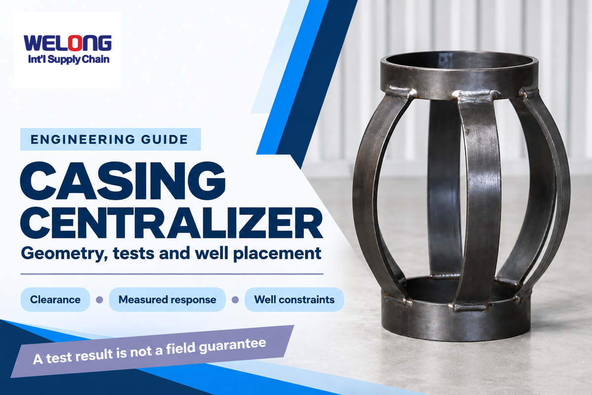
A casing centralizer is a mechanical device fitted around casing to keep the pipe away from the wellbore wall. Its contribution to a cement job starts with clearance. Selecting this casing equipment requires three connected checks: the geometry it creates, its measured behavior, and its placement within the well.
A casing centralizer supports clearance around the casing during running and cementing. Standoff describes geometry; force tests describe device behavior. Placement analysis connects both to the well, within its governing requirements.
Quick reference
- Support location and the midpoint between supports can have different standoff.
- The 67% reference discussed in API 10D testing carries specified test conditions.
- Adding units can improve support while increasing running resistance.
- Company certificates, product tests and lot records address different questions.
The surrounding cementing equipment system also includes components for fluid delivery and displacement. A centralizer changes the position of the casing; it doesn’t pump slurry or control the entire cementing sequence.
What Does a Casing Centralizer Change in the Annulus?
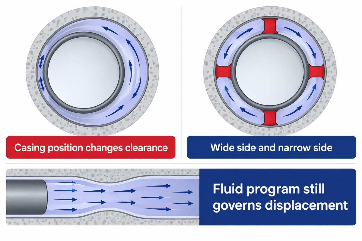
Centralizers are used for clearance between casing and the surrounding hole. When casing is off-center, the annulus has a wide side and a narrow side. Good centralization gives the fluid program a more favorable passage, although fluid properties and the pumping sequence still govern displacement.
During cementing, mud must leave the annular space. Drilling mud can remain if displacement is uneven. Pegasus Vertex describes this mechanism in its centralization discussion. In the case of the software vendor, it relates casing position to mud removal, rather than treating centralizer quantity as the complete cementing design.
A 360-degree clearance refers to a geometrical description. A centralizer doesn’t completely seal the casing, and in itself doesn’t result in a cement bond. Good cementation also involves hole cleaning, compatible fluids and the approved displacement program. Cement continuity and the connection of casing to the borehole wall concern the completed cement system.
There’s a distinction when an operation pumps the planned cement volume but later finds an isolation concern. Pumping volume shows how much fluid moved through the system. It doesn’t locate all the fluid that’s left around the pipe. Casing centralization should be included in the same review as the hydraulic plan, and not be a separate hardware count that closes the discussion.
For a more complete discussion of these tools and their functions, see the cementing tools guide. The practical question here is narrower: where does the casing need support, and how will that support behave during the run?
How Is Casing Standoff Calculated, and What Does It Leave Out?
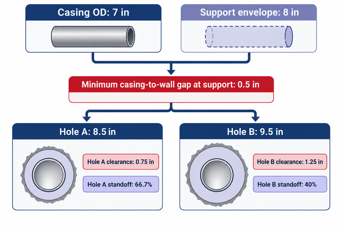
Standoff ratio expresses the minimum pipe-to-hole gap as a percentage of the nominal radial clearance. Perfectly centered circular casing has 100% standoff under this definition. Contact with the wall gives 0%. The well can have different values at a support and between supports.
For circular diameters, nominal radial clearance equals (hole diameter minus casing outside diameter) divided by two. If g is the minimum gap, the geometric ratio is 100 × g ÷ nominal radial clearance. Innova’s modeling documentation uses the equivalent eccentricity relationship and reports support and mid-joint results separately.
Example: the Annular Clearance Counterexample. Assume 7 in casing inside an idealized rigid support envelope of 8 in. The envelope touches one side of a circular hole. Its radial projection beyond the casing is (8 − 7) ÷ 2 = 0.5 in, so the closest casing-to-wall gap at that support is 0.5 in.
| Quantity | Hole A | Hole B |
|---|---|---|
| Casing OD | 7 in | 7 in |
| Idealized support envelope | 8 in | 8 in |
| Hole diameter | 8.5 in | 9.5 in |
| Nominal radial clearance | (8.5 − 7)/2 = 0.75 in | (9.5 − 7)/2 = 1.25 in |
| Minimum gap at support | 0.5 in | 0.5 in |
| Standoff calculation | 100 × 0.5/0.75 | 100 × 0.5/1.25 |
| Geometric result | 66.7% | 40% |
The larger hole leaves the same absolute gap at the contact side of the casing surface. However, that gap occupies a smaller share of the available annular clearance. Selecting a device from casing OD alone doesn’t capture this change. A blade arrangement with discrete contact points also needs its orientation and envelope considered; the circular envelope in the calculation deliberately removes that complication.
Between the supports, sag in casing can occur. Bow deformation, irregular holes and side loading can also contribute to changes. A useful well profile therefore records both the local support result and the lowest clearance along the span. Positive stand-off at the centralizer can occur at the same time as an unfavorable midpoint.
Why Is a 67% Test Reference Not a Universal Well Target?
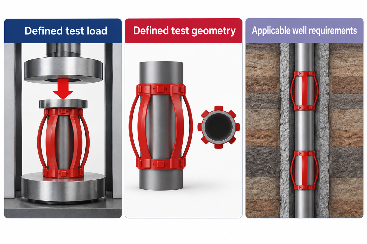
The 67% reference is relative to a defined test basis, while a well’s required centralization follows the rules and objectives of its governing design. Transferring the percentage without its load and geometry mixes two different decisions. The first is whether a device meets a test requirement. The second is whether a placement plan suits a particular well.
In its guide to API 10D seventh-edition testing, Centek describes a minimum 67% standoff ratio when the bow-spring centralizer is subjected to API test-load values. The manufacturer’s explanation also distinguishes standoff-based assessment from the older emphasis on a restoring-force minimum.
The purchasing risk is a mismatch between test conditions. Values for restoring forces recorded at one condition of the compression test aren’t the same as the standoff achieved at a specific load. Useful ranking of the two offers can’t be done without the same test basis. Nominal size and an “API” label are too little information for that comparison.
Certain regions write requirements directly. For production casing in wells governed by Illinois Part 245, Section 245.570(f) specifies rigid centralizers and at least 80% standoff in the horizontal portion. Section 245.100 defines the application of this Part to hydraulic fracturing operations. This Illinois rule is a jurisdiction-specific example, not a recognized value worldwide.
The design sequence starts with applicable requirements, then evaluates the device and placement within those constraints. “No universal target” doesn’t mean that any project can pick any target of its choice.
Read Restoring, Starting and Running Force as Different Evidence
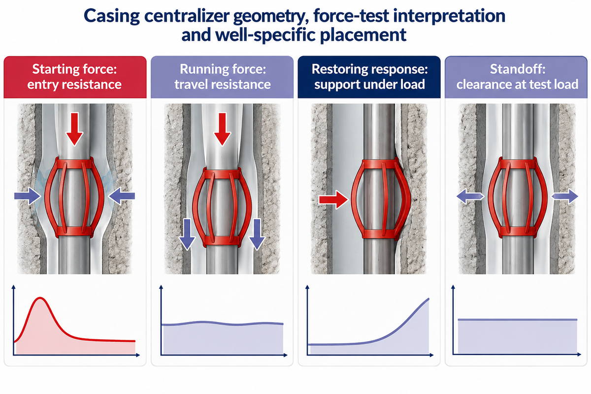
The concerns of running force, support response, and starting force address different operational questions. Therefore, a high value in one column doesn’t mean better casing running and cementing performance.
| Measurement | Useful question | Condition that must travel with it |
|---|---|---|
| Restoring response | How does the bow support the pipe under side loading? | Load-deflection curve, compression and test geometry |
| Starting force | What resistance occurs at entry? | Opening size, entry orientation and prior passage history |
| Running force | What resistance occurs during continued movement? | Travel interval, hole size and the procedure’s measurement definition |
| Standoff at test load | What clearance remains under that load? | Casing size, test opening, load and measurement positions |
Restoring forces are often presented on a curve, because support response changes with compression. A single peak or selected point conceals the rest of that behavior. Conversely, low entry resistance doesn’t always mean there’s sufficient support at the side force expected in highly inclined wells.
Care is needed with software input labels too. A program may use a manufacturer’s force data in its own calculation scheme. “Running force” may be operationally defined differently from the standardized test statistic. The governing units, curve and measurement method belong with the value when data passes from a test report to a well model.
For an underreamed well, the restriction encountered during the run may play a more dominant role in passage than the final enlarged hole. A bow that must compress through previous casing experiences a different condition from the open hole position. Passage resistance and support require separate considerations.
Build a Well-Specific Centralizer Placement Model Before Choosing Spacing
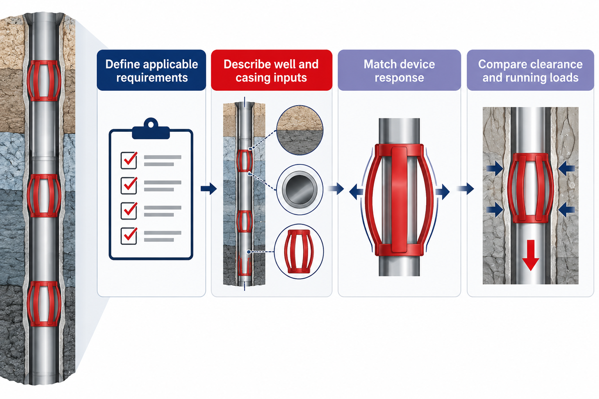
Placement models predict support along a string by combining several factors, including well trajectory, hole geometry, casing properties, and device response. Spacing follows the profile and running constraints and isn’t a result of universal distances copied from other casing programs or installation diagrams.
Petroleum engineering has considered placement an integrated problem for several decades. The abstract of the SPE paper by Lee, Smith and Tighe shows the integration of trajectory, casing properties and centralizer performance. Though modern software might provide more detailed profiles, engineering principles remain: a casing string bends and loads its supports in a particular borehole.
“Note that the total number of centralizers required and their placement on the casing are equally important.”
Device behavior and location along with installation aspects govern the modeled support response. A dogleg, a washout and a heavy string can produce different support limiting intervals even if they have the same nominal casing size.
Loading conditions can be different during running and final cementing. Fluid distributions change buoyancy, while planned pipe rotation or the ability to reciprocate changes the operating case. Where a string might buckle or contact the hole differently, the support profile and torque-and-drag review must remain connected.
Merlin’s casing-centralization guidance shows that cumulative running resistance in previous casing can be greater than resistance in the final hole, even when resistance in the final hole is zero. Additional units change more than final support placement.
- Set the governing constraints. Define applicable requirements, isolation intervals and running limits.
- Describe the well and string. Use trajectory, hole size, casing and fluid inputs for each operating case.
- Apply device behavior. Match the selected geometry and measured response to the conditions.
- Compare the resulting profiles. Review local and between-support clearance alongside running loads.
How Do Bow-Spring, Rigid and Roller Designs Change the Tradeoff?
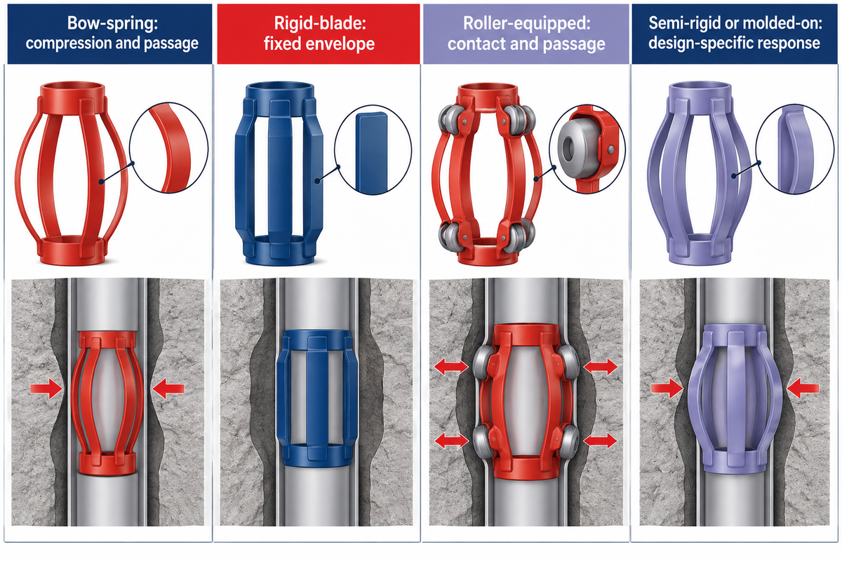
Bow-spring designs provide flexible support; rigid centralizers rely on their blade envelope; roller-equipped designs change the contact arrangement. A complete comparison of the devices’ behavior for a given case is more insightful. A family name does not rank clearance, passage resistance and rotational behavior for every well.
Bow spring centralizers exhibit shape change during passage through a restriction. Rigid blades provide a fixed geometric projection, subject to the device’s loading and structural limits. Roller construction adds moving contact features, so its evaluation also involves clearances and the intended contact surface. A rugged appearance isn’t a load-response curve.
| Family | Main design question | Comparison to make |
|---|---|---|
| Bow-spring | Support after compression and passage | Response at the relevant hole and restriction diameters |
| Rigid-blade | Available clearance with a fixed envelope | Hole enlargement, orientation, loading and between-support sag |
| Roller-equipped | Contact behavior and passage | Device-specific running and rotational conditions |
| Semi-rigid or molded-on | Response of the particular construction | Design-specific geometry, material and installation limitations |
A close tolerance annulus alters available space for device, coupling and flow path. An increased open hole changes support. Highly deviated wells alter loading and behavior of the device in deviated wellbores. Those conditions are more illuminating than a catalog statement that ranks a family as ‘best’.
For procurement, matching the envelope is the first of many considerations. Blade design, contact arrangement and installation method should enter the same operating-case review. A standard test report of a bow-spring element and a rigid-body drawing answer a portion of the considerations. Treating them as interchangeable doesn’t recognize the distinction.
Three Well Scenarios That Defeat a Catalog-Only Decision
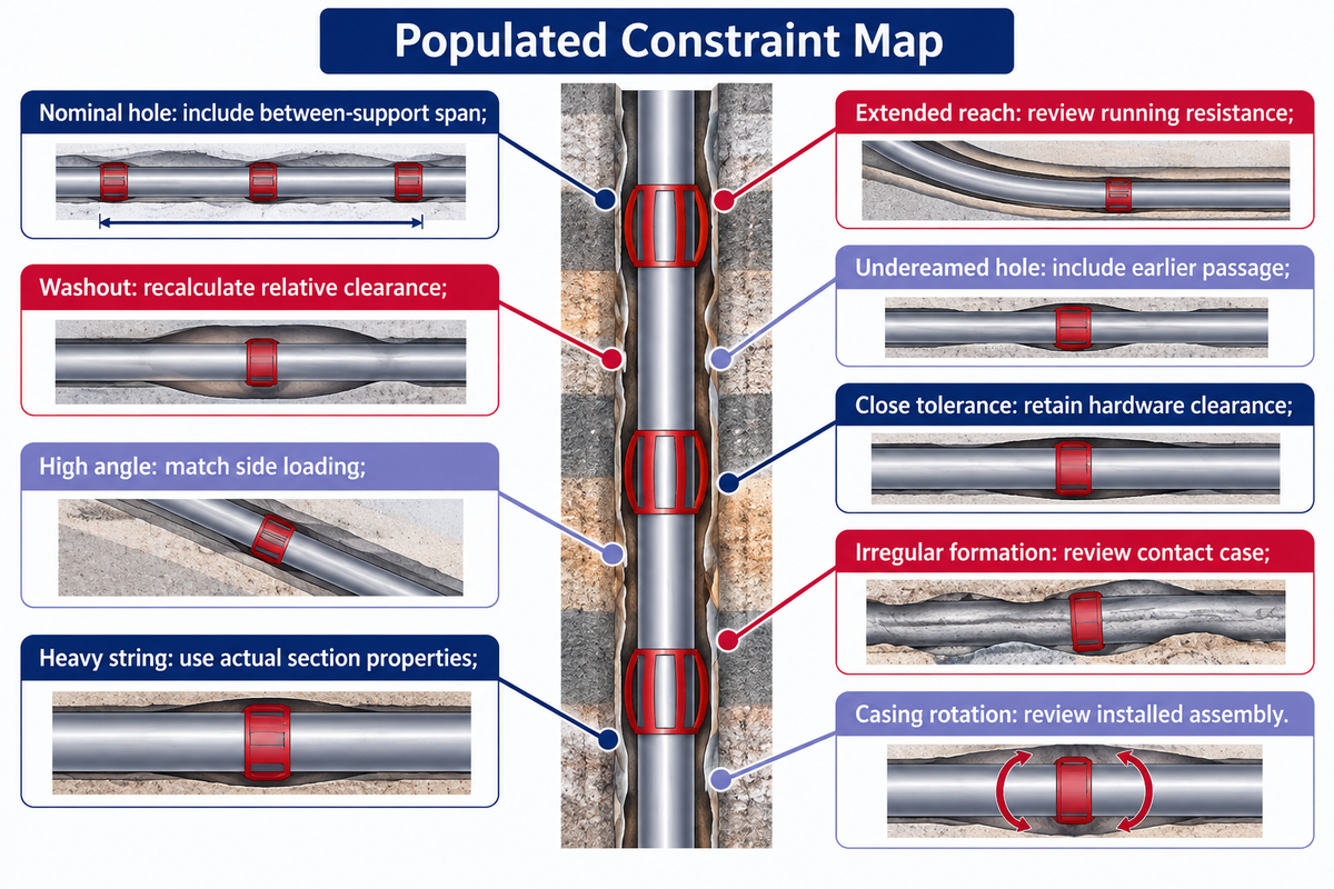
The recurring design tensions explain the need for a well model to choose a design from a catalog: Relative support changes with hole enlargement, String response changes with high-angle loading and Passage changes with an entry restriction. Hypothetical scenarios illustrating those design tensions offer decision logic rather than a universal installation method.
Scenario 1: an enlarged interval changes the geometry
A team selects a fixed-envelope design for 7 in casing on the basis of an 8.5 in nominal hole. Hole-size information then identifies an enlarged interval closer to the 9.5 in assumed diameter in the geometric example. Purchasing sees the same casing size and expects the original choice to remain adequate. Engineering sees a different relative clearance: the calculated support-location ratio falls from 66.7% to 40% under the stated assumptions. The decision returns to the modeled interval and allowable device geometry. Increasing the quantity alone doesn’t change the blade height at each existing support, and the space between supports still needs a sag calculation.
Scenario 2: local support competes with running load
A more detailed analysis of side loading is required for the highly deviated section. From a control point of view, operations must also land the string. Thus, the comparison includes the accumulated running effect and casing movement permitted by the program. A stronger local support response can be useful while the combined run becomes more difficult. Engineering compares the centralization profile and torque and drag case. A lower unit price by procurement doesn’t control the saving when the arrangement impacts the running effect. No generic friction coefficient can resolve that conflict without the well and device inputs.
Scenario 3: the final hole is not the restriction
A free expanse exists for a bow-spring device to increase in size in an underreamed interval, but first the device passes through previous casing. A quotation built around final-hole dimensions can leave the earlier compression and entry case out of view. The final support profile is also essential. A device that appears attractive in the enlarged interval may have a different running burden before it arrives there. The float-equipment arrangement also is a part of the complete casing program, and centralizer selection should not silently redefine the rest of the string.
Halliburton’s reported offshore case describes tailoring blade placement and assessing torque and drag for its own centralization technology. The main point is combined design review, not assurance that another technology would yield the same results.
| Well or operating condition | Hidden constraint | Decision consequence |
|---|---|---|
| Near-vertical, nominal hole | Support between installed locations | Include the span, not only the device position |
| Washout | Larger clearance denominator | Recalculate the relative support profile |
| High-angle interval | Side loading | Match device response to the load case |
| Deep, heavy casing string | String properties and loading | Use the actual section properties |
| Extended reach | Accumulated running resistance | Review support and running together |
| Underreamed hole | Earlier restriction passage | Include pre-passage and post-passage behavior |
| Close tolerance | Envelope and adjacent hardware | Retain passage and flow-path clearances |
| Fragile or irregular formation | Contact conditions | Use the intended hole-contact case |
| Planned casing rotation | Contact and retention arrangement | Review the complete installed assembly |
How Can You Review Centralizer and Stop-Collar Evidence?
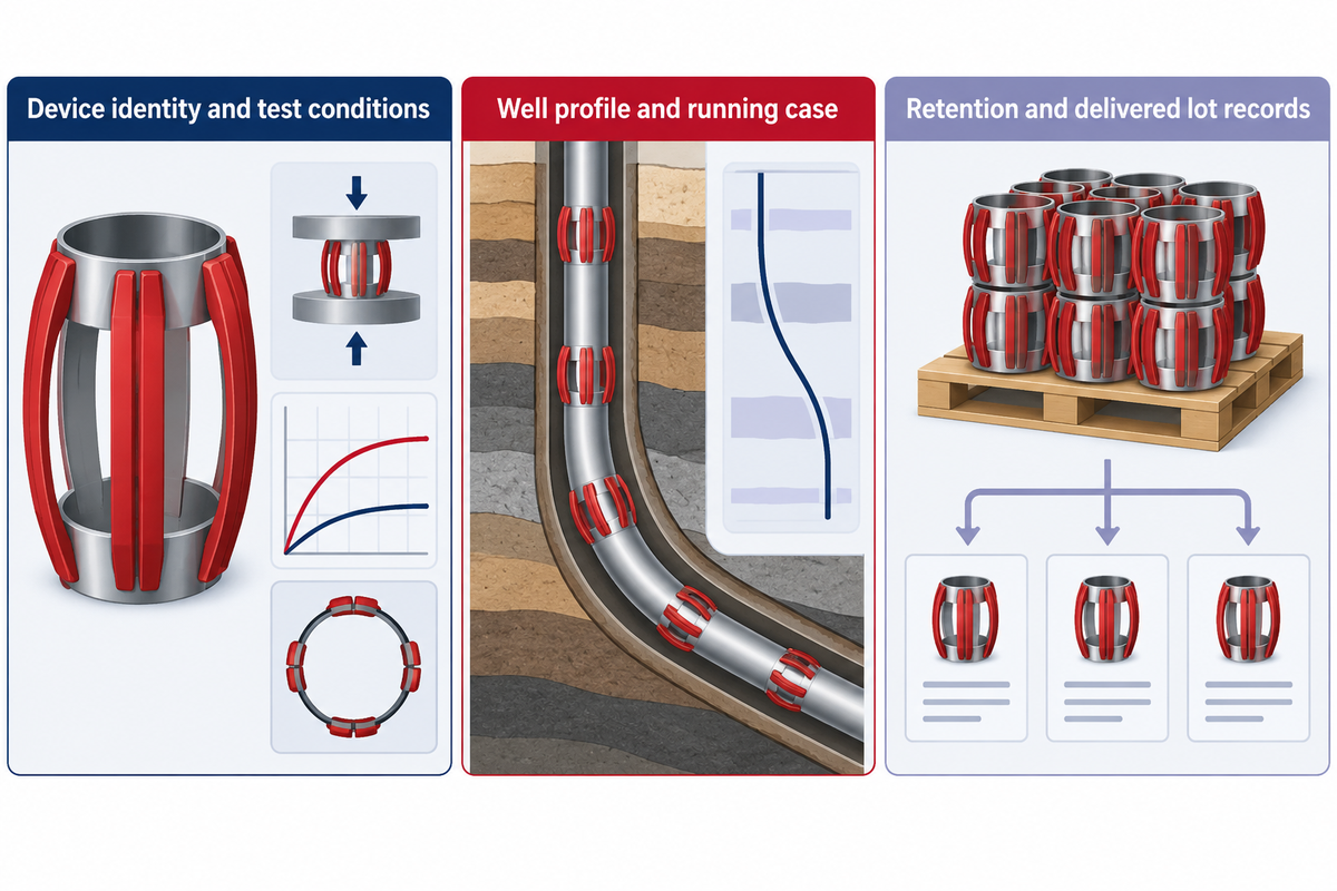
Centralizer evidence should be assessed against the device, test conditions and intended operating case. Proper installation includes axial retention, so the stop collar and its method of assembly are to be evaluated as a unit.
The Test-to-Well Evidence Crosswalk below provides a means of transforming a pile of documents to specific decisions. It separates laboratory measurements from calculated well behavior and delivered lot identity. Blank fields in an offer remain open engineering or purchasing items rather than favorable assumptions.
| Record or condition | What must match | Decision consequence | Owner |
|---|---|---|---|
| Design identity | Part number and construction | Connect results to the offered device | Quality |
| Casing dimensions | Specified OD and relevant tolerances | Avoid comparing different fit conditions | Engineering |
| Test opening | Hole or test-pipe ID | Keep compression conditions comparable | Quality |
| Restriction passage | Restriction size and sequence | Evaluate the earlier running case | Engineering |
| Compression history | Conditioning and prior passage | Compare the same device state | Quality |
| Support response | Curve, load basis and units | Use response at the relevant load | Engineering |
| Starting-force result | Entry geometry and orientation | Interpret entry resistance consistently | Engineering |
| Running-force result | Procedure and reported statistic | Separate travel resistance from support | Engineering |
| Well standoff profile | Trajectory, hole and string inputs | Review supports and spans together | Engineering |
| Retention evidence | Stop collar, casing and assembly method | Assess axial securing separately | Quality / operations |
| Lot records | Delivered identity and test references | Maintain traceability into the order | Quality / procurement |
| Commercial scope | Agreed design and documentation | Compare equivalent offers | Procurement |
Under the purchasing package, request the specified test edition, device identity, test geometry, force or load-response data, and the relevant installation and retention records. Confirm the name of the product manufacturer and the name of the organization that issued each report. Keep these requests together so a supplier can respond to them against one defined casing program.
Mike Moffatt’s JPT technology article, securing centralizers against axial movement, treats this issue as a separate concern. Defining a support envelope and affixing it to the string are linked engineering activities; however, they aren’t the same thing.
Does an API 10D Test Report Mean an API Monogram License?
No. API removed Specification 10D from its Monogram Program effective January 1, 2020, according to its official program notice. A supplier’s statement about testing to a specified edition is a separate claim from a Monogram license.
ISO 9001 addresses a quality-management system. API 7-1 concerns rotary drill stem elements. Neither changes the scope of a centralizer test into something else. Organization and facility credentials belong with their stated scope, while the offered centralizer design and delivered lot retain their own records.
Troubleshoot Symptoms Without Guessing the Cause
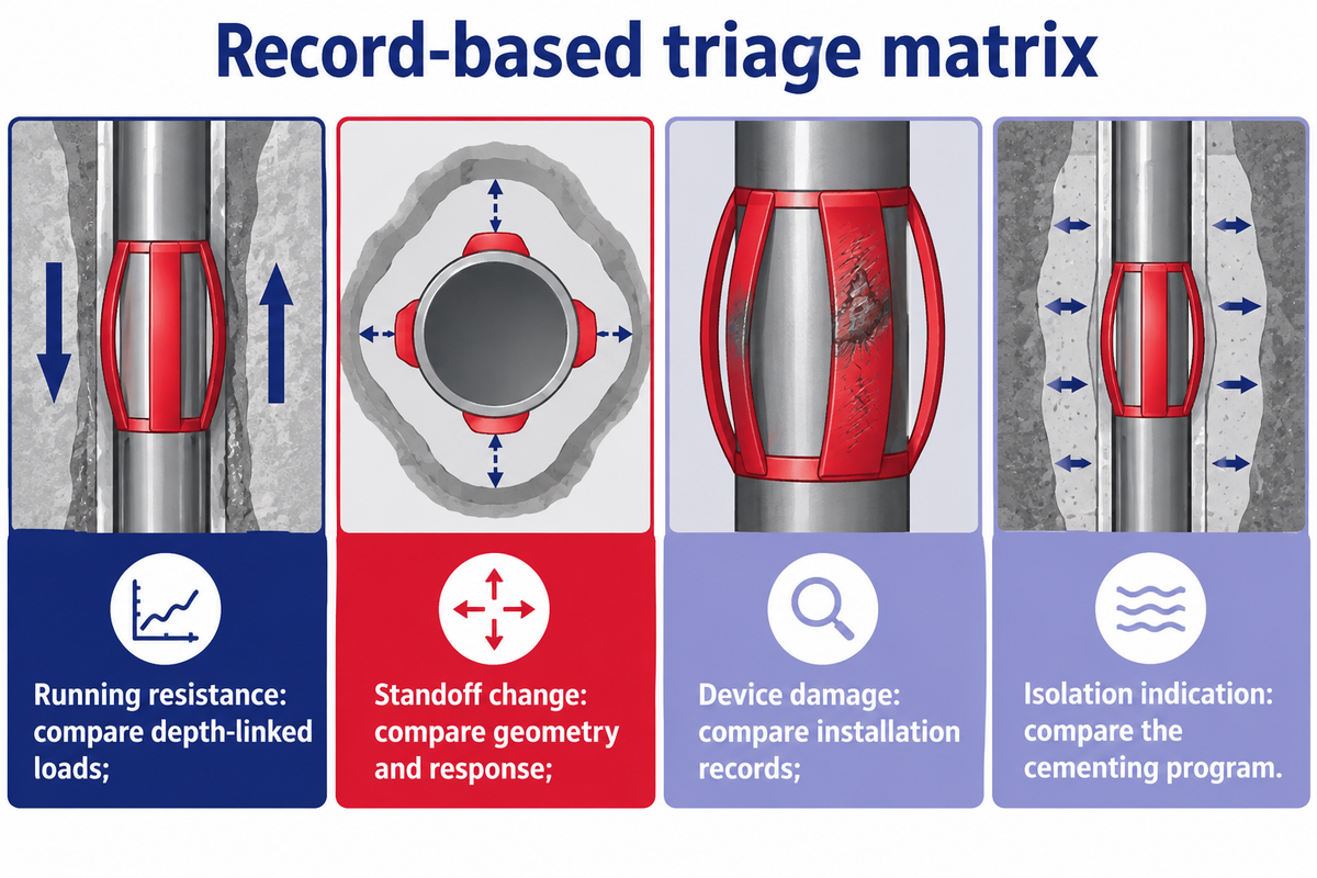
Troubleshooting begins with a comparison of the observed change with the prevailing operation and the expected response. Symptoms differ and include an increase in drag force, bow damage and an unfavorable cement evaluation. Interpretation of the symptoms requires review of the relevant records. Replacing a centralizer family based on the single symptom may leave the cause of the issue unsolved.
Chris Lenamond’s AADE conference paper on hole monitoring contains a casing running example of a nearly constant hook load accompanied by increasing drag because the modeled string weight should have increased with depth. This published case illustrates why the direction of a surface reading must be assessed in the context of the operations and the model. It isn’t a universal field trigger.
| Observation | Possible questions | Records to compare |
|---|---|---|
| Unexpected running resistance | Restriction, hole condition, device compression or model inputs? | Depth-linked loads, geometry and operating state |
| Lower modeled standoff | Enlargement, loading, spacing or input change? | Survey, hole size, string properties and device response |
| Installation damage or movement | Assembly, passage or retention issue? | Device identity, installation record and inspection findings |
| Poor zonal isolation indication | Geometry, displacement, cement system or evaluation conditions? | Cementing program, operational record and qualified evaluation |
Hole cleaning, differential sticking risk and the contact environment can influence casing operations in addition to the centralizers. A revised diagnosis should account for the change in the record. Operational adjustments remain within the approved well program and the responsible team’s limits.
What Is Changing in Centralization Analysis?
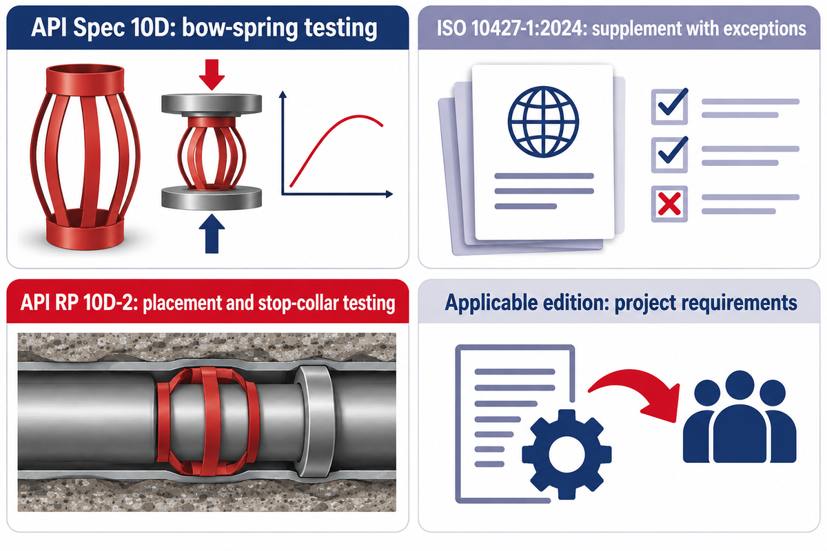
Recent document changes make edition control a practical purchasing issue. ISO 10427-1:2024 and the 2023 edition of API RP 10D-2 address different parts of centralization work. It is more constructive to keep the specified edition and applicable requirements with the purpose of the document, than replace every old document with the latest edition.
The official ISO abstract describes ISO 10427-1:2024 as a supplement to API Spec 10D seventh edition (2021), with stated exceptions. The API publication catalog separately lists RP 10D-2, second edition, August 2023, for placement calculations and stop-collar testing.
| Document or requirement | Role in the review | Edition decision |
|---|---|---|
| API Spec 10D, seventh edition | Bow-spring testing, performance and marking | Retain the specified test basis |
| ISO 10427-1:2024 | Supplement to the 2021 API edition with exceptions | Apply the identified supplement and exceptions |
| API RP 10D-2, second edition, 2023 | Placement and stop-collar testing | Keep its role separate from the device test specification |
| Contract or incorporated legal edition | Requirements governing the project | Use the edition made applicable to that project |
Illinois Section 245.115 serves as an example of fixed incorporation and names specific documents, thus excluding later additions and/or deletions from such incorporations. Publication currency and legal applicability are, therefore, distinct questions.
Design development also continues at the assembly level. US12305452B2, published in 2025 and naming Downhole Products Ltd as assignee, describes an internal stop-collar arrangement. That specific disclosure concerns its authors’ design; it isn’t a statement about Welong’s patents or an industry-wide performance improvement.
Key takeaway
A useful centralizer comparison connects device geometry and measured response to the complete casing program. Preserve the test conditions, model the support profile and review the running case within governing requirements.
Frequently Asked Questions
What are the different types of casing centralizers?
Common families include bow-spring, rigid-blade, semi-rigid and molded-on designs.
Common design families include bow-spring, rigid-blade, semi-rigid and molded-on centralizers; roller-equipped designs add another contact arrangement. Those labels describe construction rather than a universal ranking. Compare the actual device envelope, load response, passage through restrictions and behavior in the intended hole. Installed standoff changes with hole size, side loading and the distance between supporting units along the casing.
How does a casing centralizer work?
It supports clearance between casing and the surrounding hole.
A centralizer places supporting contact features around the casing so that the pipe has clearance from the surrounding borehole or previous casing. Bow-spring devices respond through flexible bows; rigid devices rely primarily on their geometry. The resulting annular clearance supports the cementing plan, but successful mud displacement also depends on the fluid program and well conditions. Centralizers alone can’t guarantee zonal isolation.
How many casing centralizers are needed?
The required count follows the governing requirements and well-specific placement analysis.
There’s no single count that suits every casing string. Start with the well trajectory, hole geometry, casing properties, fluid conditions, device performance and the intervals that need isolation. Model the standoff profile between devices as well as at them, then check the placement against running limits. The accepted count follows that review; multiplying joints by a generic installation rule skips the controlling conditions.
Does 67% standoff guarantee a successful cement job?
No. Cementing performance involves more than a geometric percentage.
Mud removal and cement bonding also depend on well geometry, fluids and execution of the approved cementing plan.
Are centralizers required?
Yes where the applicable well rules or approved casing program require them.
Those requirements also affect placement. Illinois Part 245 provides one scoped example, rather than a rule for every well worldwide. Even when centralization is specified, the equipment package still needs a defined device, stated test basis and placement model. The installation plan includes restrictions, stop collars and intended casing movement. Engineering, quality and purchasing each have a role in connecting that package to the delivered order.
Shift focus to products from designs. Carry the casing and hole geometry, restriction sequence, intended placement and required documentation into a review of casing centralizer solutions. China Welong can support the oilfield product supply-chain. A defined technical package provides a starting point to the product discussion.
For the surface delivery aspect of the program, see the cement-head equipment route. To share the defined purchasing package, use the project enquiry form or contact China Welong.
Technical basis: Public standards summaries, authored engineering publications and explicitly assumed geometry. The examples are teaching aids. Well design and field execution will remain subject to the requirements of the governing authority and the approved program.
References & Sources
- ISO: ISO 10427-1:2024 official abstract.
- API: published catalog, centralization documents, page 21.
- Centek: API 10D seventh-edition testing explanation, manufacturer guidance.
- Innova: Casing Standoff Quick Start Guide, model-specific documentation.
- Merlin ERD: Casing centralization, 2019, modified 2023.
- Gefei Liu, Pegasus Vertex: Buried Jewelry: Casing Centralizers, 2014.
- API: 10D Monogram Program removal notice, April 2019.
- Lee, Smith and Tighe: Optimum spacing for casing centralizers, SPE13043, 1984 abstract available at OSTI.
- Illinois: 62 Ill. Adm. Code Part 245, Sections 245.100, 245.115 and 245.570.
- Mike Moffatt, JPT: centralizer attachment-system discussion, 2017.
- Halliburton: tailored centralization in a deepwater campaign, supplier-reported case.
- Chris Lenamond: AADE-03-NTCE-24, 2003, casing-running discussion.
- Downhole Products Ltd: US12305452B2, Centralizer having internal stop collar, 2025 publication.
Why Buyers Work With Welong
About Welong Engineering Support
China Welong supports oilfield buyers with engineered supply-chain service for drilling tools, well-control equipment, rig-floor tools, casting parts, and industrial forged components.
Project Review Before RFQ
We help buyers compare tool family, material route, API or ISO requirements, inspection records, supplier capability, delivery risk, and documentation needs before a purchase decision is finalized.
Request An Oilfield QuoteCompany Profile // Data Sheet
CompanyChina Welong International Supply Chain
BrandWelong
CountryChina
Business TypeOilfield tools and industrial supply-chain partner
Main ProductsDownhole drilling tools, fishing and milling tools, wellhead and well-control equipment, oilfield hoses, rig-floor handling tools, mill rolls, and forgings
Engineering CapabilityTool-family selection, specification envelope review, API / ISO reference support, material traceability, inspection coordination, and supplier-route comparison
RFQ Data NeededTool type, size, connection, rating, grade, standard, quantity, drawings, and delivery target
Websitewelongoiltools.com