Get in touch with Welong Company

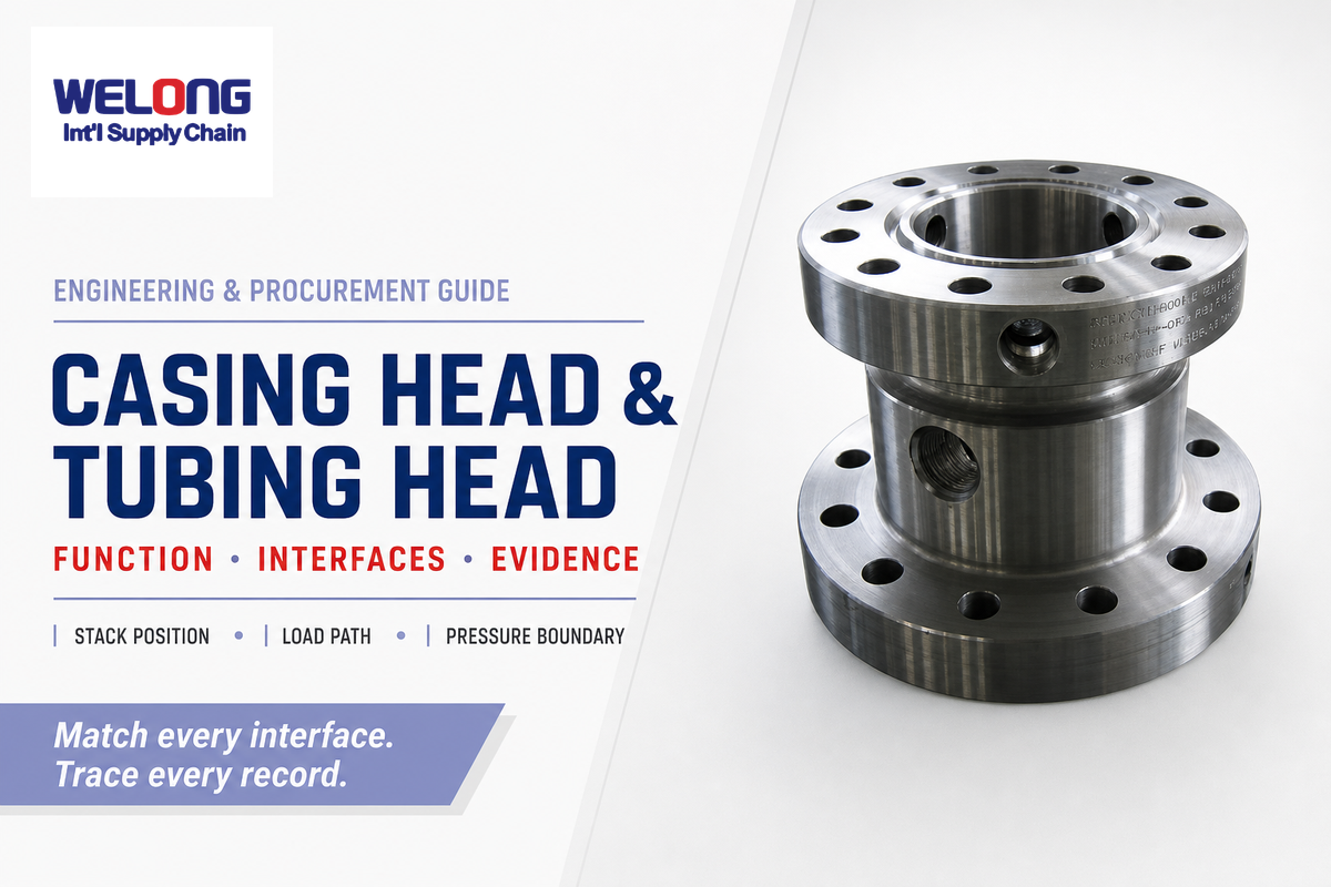
The selection of Casing Head and Tubing Head isn’t a matter of matching catalog names. A casing head supports and seals casing strings near the lower wellhead; a tubing head supports the production-tubing hanger and contains the tubing-to-production-casing annulus above it. Approved stack drawings, load cases, seal profiles, service conditions, and order records must be mutually consistent before treating the two components as compatible.
Updated October 2026. This engineering guide explains functions, evidence and hold points. Project specifications, along with controlled manufacturer drawings and approved field procedures, remain authoritative.
A high-pressure wellhead assembly must support load as well as pressure containment. Reliable control of the wellhead depends on seal integrity and annulus pressure monitoring, not on a single catalog name. That’s the reason why safe and efficient well operations begin by assigning every interface to an engineering owner.
Key takeaway
Compatibility is proved across the full load, pressure, seal and mating-interface chain; one matching flange label cannot approve a wellhead stack.
In this guide
- Separate casing-head and tubing-head duties.
- Trace 12 interfaces instead of matching one nominal size.
- Build a 12-input compatibility matrix and four-packet requisition.
- Use five installation hold points without inventing field values.
- Route eight failure signals to evidence before repair decisions.
Casing Head vs. Tubing Head: Position, Load Path, and Pressure Boundary
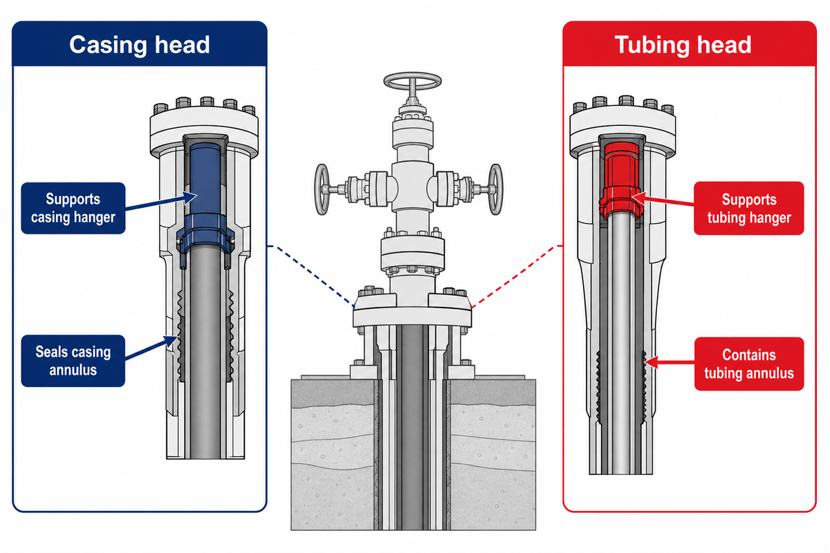
A casing head is the lower wellhead body that supports the next casing string via a casing hanger and seals the associated casing annulus. A tubing head is placed higher in the production stack; it receives the tubing hanger, suspends production tubing and contains the annulus between the tubing and production casing.
Casing head
- Located near the lower end of a conventional surface wellhead.
- Receives a casing hanger for the next casing string.
- Transfers suspended casing load into the wellhead support path.
- Provides sealing and access around a casing annulus.
Tubing head
- Located above the casing-head or casing-spool section.
- Receives the tubing hanger for the production tubing string.
- Transfers suspended tubing load into the production wellhead.
- Provides the pressure boundary and access for the tubing annulus.
The words head, spool and housing are used inconsistently in informal specifications. The functional question is more reliable: which string is suspended, which annular space is sealed, where the side outlet communicates, and which lower and upper interfaces close the pressure boundary? SLB’s public glossary differentiates a casing spool from a tubing head by those functions, and API Spec 6A’s public page groups wellhead and tree equipment within a product-standard scope. Neither source allows the two catalog names to be treated as interchangeable .
What is the difference between tubing and casing?
Tubing and casing are pipe strings, while tubing heads and casing heads are surface wellhead components. Casing supports the wellbore and isolates formations in successive strings. Production tubing provides the controlled flow path to or from the reservoir. Their hangers transfer load into different bowls, and their heads seal different annuli. Confusing the string with the housing hides who owns the load shoulder, seal bore and outlet path. In the interface verification record, list the casing and tubing programs separately, and identify which hanger, annulus and surface equipment belongs to each program. This simple differentiation prevents a pipe-size entry from being misinterpreted as a complete head assembly.
At the top of the surface casing, a casing head body becomes part of the wellhead system that carries the next suspension stage. The casing head supports the weight transferred through its hanger; the detailed calculation must include the weight of subsequent casing strings rather than treating the casing pipe outside diameter as a load value. Its seals must seal the annular boundary defined by the approved design.
A conventional wellhead system may use a tubing head spool installed on top of the casing head or an intervening casing spool. The exact wellhead equipment may instead use a mandrel hanger or another qualified arrangement, so the surface casing string schedule and controlled drawing make the decision.
| Check | Casing head | Tubing head |
|---|---|---|
| Supported string | A casing string through its hanger | Production tubing through the tubing hanger |
| Primary annular responsibility | Casing-to-casing annulus for the relevant stage | Tubing-to-production-casing annulus |
| Stack position | Lower wellhead | Above casing section, below tree transition |
| Selection proof | Lower preparation, bowl, hanger, seals, outlets and upper interface | Lower mate, tubing-hanger system, seals, penetrations and tree adapter interface |
Where Each Component Sits in the Wellhead Stack
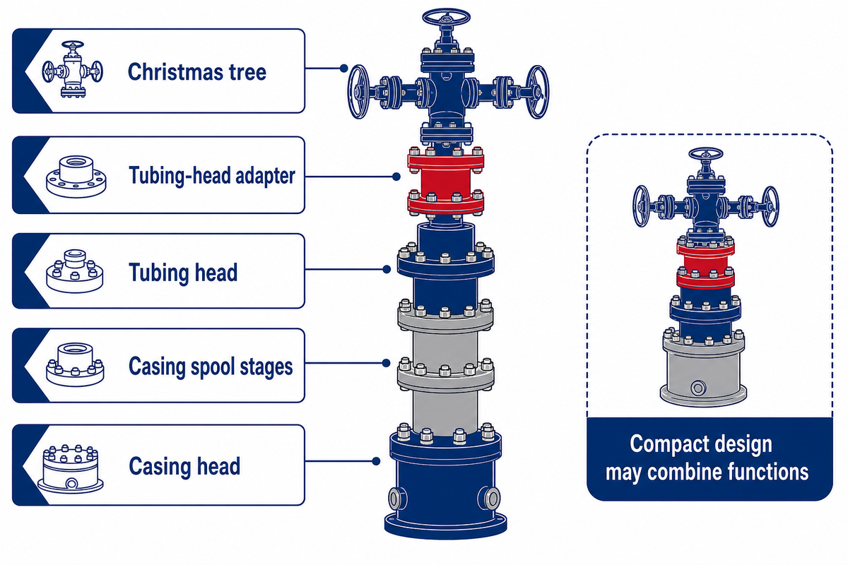
In a conventional surface stack, the path typically rises from surface casing and casing head through any casing spools to the tubing head, tubing-head adapter and Christmas tree. That ordered list delineates the interfaces, but isn’t an exhaustive listing of all potential points of connection: compact and unitized wellheads may combine many functions.
- Anchor the lower wellhead — identify the surface-casing attachment and the first pressure-containing body.
- Suspend successive casing strings — map each casing hanger, bowl, annulus and spool transition.
- Install the tubing-head function — locate the tubing-hanger bowl, annulus outlets and control penetrations.
- Close the tree transition — verify the adapter, upper seal geometry, bore and rating handoff.
- Prove the assembled boundary — reconcile the drawing, procedure and order-specific acceptance record.
This sequence also accounts for the distinction between a blowout preventer and a Christmas tree in a wellhead. Across drilling and production, the BOP is connected to the wellhead arrangement that’s used for pressure control during drill work, while the Christmas tree controls the path of the production fluid above the tubing-head arrangement. Equipment changes with the operation. Remaining interface obligations, however, don’t change. See the broader wellhead and well-control equipment family, wellhead Christmas tree and the separate blowout preventer equipment roles.
Onshore and offshore stacks can expose different installation constraints, while a subsea or hybrid completion changes where equipment is situated. The borehole program determines which casings and tubings are to be supported. During drill, completion and well intervention work, the BOP stack and temporary interfaces must be assessed against the operation-specific wellhead assembly.
The P0-2 evidence review identified an important exception with the 2024 unitized-wellhead case that describes an integrated architecture of functions that typically span over several conventional bodies. The safe assumption isn’t that all unitized products integrate functions in the same manner. The safe assumption is that four interfaces don’t mandate four separate housings. Procurement should request a function-to-body map for the proposed design.
The Stack Interface Responsibility Grid
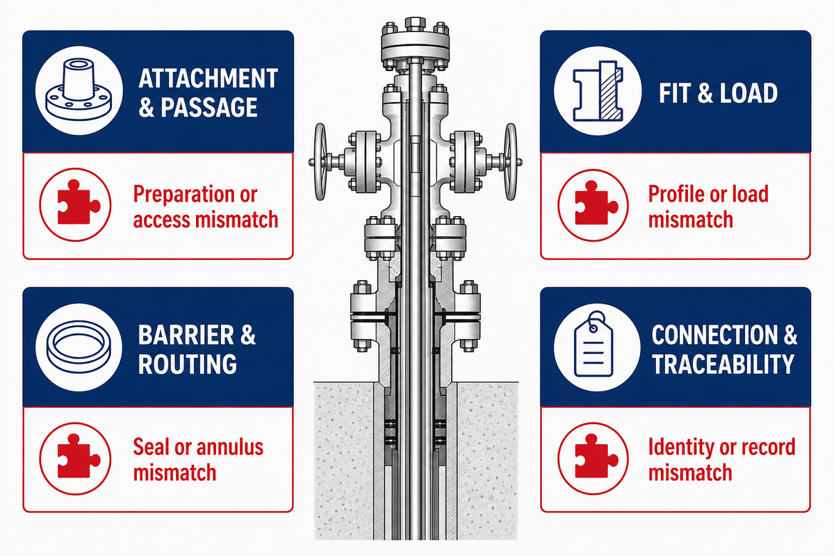
The Stack Interface Responsibility Grid verifies each load, pressure, seal, outlet, and mating handoff prior to approving a stack. It binds each interface area to its controlling record and states the mismatch condition that requires resolution when a profile, load case, pressure boundary, or component identity cannot be reconciled.
The boundary check starts with the current API Specification 6A scope; the order-specific drawing and acceptance record then show how that boundary is implemented.
Nominal flange matches only reveal part of a boundary. Other elements require the following. A buyer still needs to know whether the casing hanger fits the bowl, the secondary seal fits the casing outside diameter and preparation, the bore preserves required access, the side outlet reaches the intended annulus, and the next component closes against the correct seal profile. The grid below turns these dependencies into interface areas, controlling records, and mismatch conditions.
A flanged connection exposed to high pressures needs to be assessed the same way. Ring-groove fits don’t prove the internal seal path. Two side outlets may support monitoring or control duties, but the drawing must show which annulus each reaches. Lockdown screws, where part of the qualified design, must be installed under the controlled procedure rather than a generic setting.
| Link / interface area | Evidence record to match | Mismatch condition |
|---|---|---|
| Attachment class. Lower attachment | Casing preparation, weld/thread/slip arrangement and controlled drawing | Preparation or load path is undefined |
| Passage class. Body bore | Bore, drift and tool-access requirements | A downstream operation cannot pass |
| Fit class. Hanger bowl | Bowl profile and hanger family | Profile is inferred from nominal size |
| Load class. Suspended load | String weights and governing load combinations | Load basis or design owner is missing |
| Barrier class. Primary hanger seal | Seal profile, service and qualification boundary | Material or pressure-temperature basis differs |
| Barrier class. Secondary seal | Casing OD, preparation, tolerance and seal design | Published range is mistaken for actual fit |
| Routing class. Annulus outlet | Port routing, valve interface and monitored annulus | Outlet communicates with the wrong space |
| Retention class. Lockdown/load retention | Approved locking arrangement and procedure | Generic screw count substitutes for design evidence |
| Connection class. Upper flange | Size, rating, facing and ring-groove details | Only the nominal label matches |
| Transition class. Adapter seal bore | Hanger neck, packoff, bore and penetrations | Tree transition is not shown on the drawing |
| Rating class. Pressure-class handoff | Governing pressure case and every adjacent rating | A higher label masks a weaker adjacent boundary |
| Traceability class. Record handoff | Approved drawing, bill of materials, inspection and acceptance records | The physical unit cannot be tied to its evidence |
Do casing head and tubing head need to match?
They must be compatible at all shared and system interfaces; however, that doesn’t mean they must be identical products of an undifferentiated catalog family. Flange and ring-groove geometry must be confirmed, as must the bore and drift, the pressure-temperature basis, materials, seal profiles, hanger relationships, outlets, penetrations, and load combinations. A mixed-vendor stack needs an explicit interface owner and approved reconciliation record; a same-vendor stack still needs order-specific proof.
Four Components, Four Different Interface Jobs
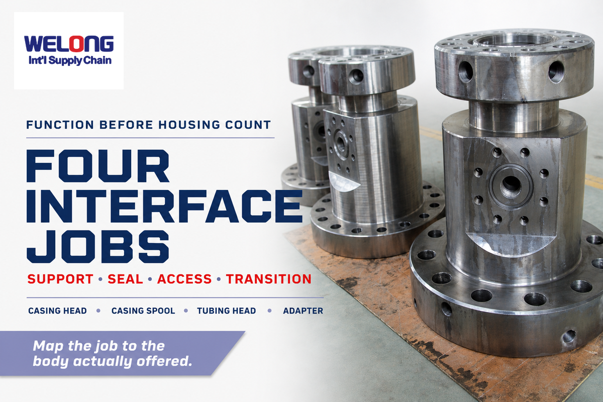
In a conventional stack, casing heads, casing spools, tubing heads and tubing head adapters describe distinct interface functions. They should not be written as four mandatory housings. A compact design may incorporate several functions within a single component while a conventional design may allocate a single function across several components.
The University of Texas PETEX wellhead overview separates casing-support, sealing and pressure-bleed functions; that functional view is more reliable than counting catalog bodies.
| Component or interface | Main job | Not sufficient proof |
|---|---|---|
| Casing head body | Connect the lower wellhead to surface casing | A body label without lower-preparation data |
| Casing hanger | Suspend a casing string in the matched bowl | Nominal casing size without profile and load basis |
| Casing spool | Add a hanger bowl, seal transition and annulus-access stage | Matching flange size alone |
| Secondary casing seal | Close the intended casing annulus against the prepared surface | A published outside-diameter range without tolerance review |
| Annulus outlet | Provide controlled access to the identified annular space | Port count without an internal communication map |
| Tubing head body | Receive the tubing hanger and contain the production annulus | A pressure class without tubing-hanger geometry |
| Tubing hanger | Suspend tubing and carry seal or control-line interfaces | Tubing size without neck, bore and penetration data |
| Lockdown system | Retain the qualified hanger or seal arrangement | A generic screw count or torque value |
| Tubing-head adapter | Transition from hanger/head geometry to the tree | A tree flange match without seal-bore checks |
| Tree mating interface | Close the upper pressure and flow-path handoff | A catalog family name without the approved stack drawing |
A line item such as “wellhead head, complete” allows various suppliers to provide various scopes. One may give the hanger and secondary seals, while another may omit the adapter and/or annulus valves. A responsibility matrix should name the body, hanger, seal, outlet, lower mate, upper mate, installation stage and excluded scope. This makes deviations visible before the purchase order, not during stack-up.
The 12-Input Compatibility Matrix
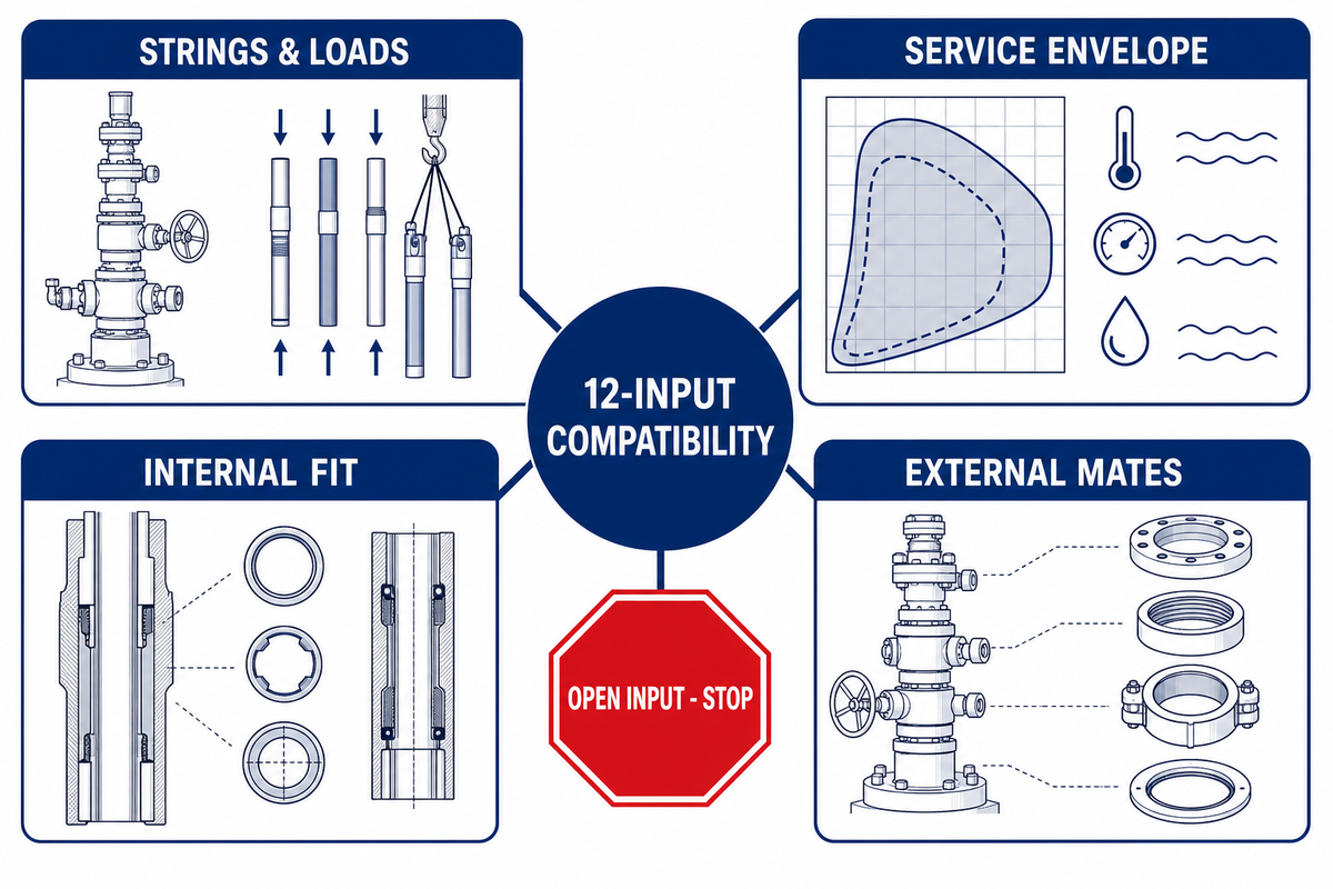
Compatibility is established across 12 project inputs: casing program, tubing program, loads, pressures, temperature, fluid service, material class, contractual product level, hanger profile, seals, outlets and mating connections. If one of the governing inputs is open, selection should pause at that interface rather than substitute a catalog assumption.
| Input | What it can change | Evidence owner | Do not infer |
|---|---|---|---|
| 1. Casing program | Body, bowl, hanger, secondary seal and lower connection | Well design and casing schedule | Fit from nominal OD alone |
| 2. Tubing program | Tubing hanger, neck, bore, penetrations and adapter | Completion design | Hanger geometry from tubing size |
| 3. Suspended loads | Hanger/body design and load combination | Engineering calculation | Capacity from pressure class |
| 4. Governing pressures | Rated working pressure and adjacent boundary checks | Approved pressure basis | Acceptance test value from rating label |
| 5. Temperature | Seal system, materials and qualification envelope | Design basis and service profile | Ambient suitability for operating temperature |
| 6. Fluid/service | Material selection, elastomers, corrosion and sour-service controls | Fluid analysis and governing specification | Material class from well location |
| 7. Material class | Pressure-containing and wetted-part requirements | Contract and material specification | Whole-unit conformance from one certificate |
| 8. Contractual product level | Qualification, inspection, test and documentation scope | Purchase specification | Required level from a generic API reference |
| 9. Bowl/hanger profile | Mechanical fit, load shoulder and packoff | Controlled interface drawing | Interchangeability from size and rating |
| 10. Seal arrangement | Primary/secondary barriers and installation sequence | Qualified design and manufacturer procedure | Universal seal test or energization method |
| 11. Outlets/penetrations | Annulus access, valves, gauges and control lines | P&ID, stack drawing and completion controls | Communication path from port count |
| 12. Mating connections | Flange, ring groove, thread, bore, drift and transition | Interface-control document | System compatibility from one matching flange |
Published dimensions and pressure values are examples tied to a specific design. One published peer-reviewed study tested a prototype of one 8 1/8-inch casing-hanger at 175 MPa. In one reported hold, pressure moved from 180.33 MPa to 179.64 MPa, a change of 0.69 MPa, and the reported leakage rate was 0.366 × 10⁻⁴ Pa·m3/s. There are many factors that act on the system. The useful lesson is that geometry, contact stress, material and pressure-temperature conditions interact. 175 MPa, any 5-minute hold, and the reported test result are not universal field acceptance values . Therefore, the matrix is asking for evidence rather than a false selector.
The table below keeps the paper’s numbers attached to that one research configuration. They’re provided to show the relationship of design, analysis, test setup, and inspection, not to supply project selection ranges or field procedures.
| Study record | Published values | What a buyer may conclude |
|---|---|---|
| Research pressure case | 175 MPa on an 8 1/8-inch mandrel-hanger prototype | The paper studied that configuration, not every casing head |
| Selected seal geometry | 3 mm boss radius, 90° bottom angle, 5.91 mm effective contact width | Geometry and performance cannot be separated |
| Parameter scan | 2.9 mm to 3.1 mm and 90° to 96° | The selected point came from a bounded study range |
| Model loading | 2.5 mm preload displacement followed by 175 MPa medium pressure | A test pressure without its loading sequence is incomplete evidence |
| Mesh check | 0.2 mm local mesh, 477.4 MPa reported stress and less than 1% relative error | Simulation results depend on the documented model controls |
| Prototype geometry | 18 mm height, 15 mm upper width, 13 mm lower width and 175.75 mm radius | The tested part has a specific geometry, not a generic H-ring label |
| Instrument calibration points | 25%, 50% and 75% of maximum range | The measurement chain is part of the acceptance record |
| Paper-reported acceptance basis | 5 minutes of stable pressure and no more than 3.45 MPa pressure drop | Use only as the paper’s test basis; the project procedure still controls |
| One measured run | 180.33 MPa start, 179.64 MPa finish and 0.7 MPa reported drop | A result is traceable only with its specimen and method |
| Post-test inspection | 100% liquid penetrant inspection, 30 minutes developer dwell and 365 nm ultraviolet light | Pressure data did not replace surface inspection |
| Reported profile comparison | 4.0% and 35.0% contact-width differences; 4% uniformity improvement | Comparative results remain limited to the paper’s profiles and model |
Scenario – replacement body with a familiar designation. A project team reviews a replacement proposal where the nominal size and working pressure of the body match those on the existing stack. The mismatch becomes visible in the interface-control drawing: the proposed bowl profile belongs to another hanger family, and the secondary seal assumes a different casing preparation. The correct action isn’t to “make it fit” during installation. Hold the order, identify the interface owner, and have the supplier resolve the bowl, hanger, seal, load case, and upper mate in one controlled drawing. The designation starts the search; it doesn’t close the compatibility review.
Published ranges may cover various sizes, but size breadth doesn’t establish a pressure-tight seal for this project. Record the temperature class and contractual PSL along with the working pressure, material class and service. If a mandrel or slip hanger option changes the load path, treat it as a configuration decision rather than an accessory substitution.
Pressure Rating, Material Class, and Standards: What the Evidence Proves
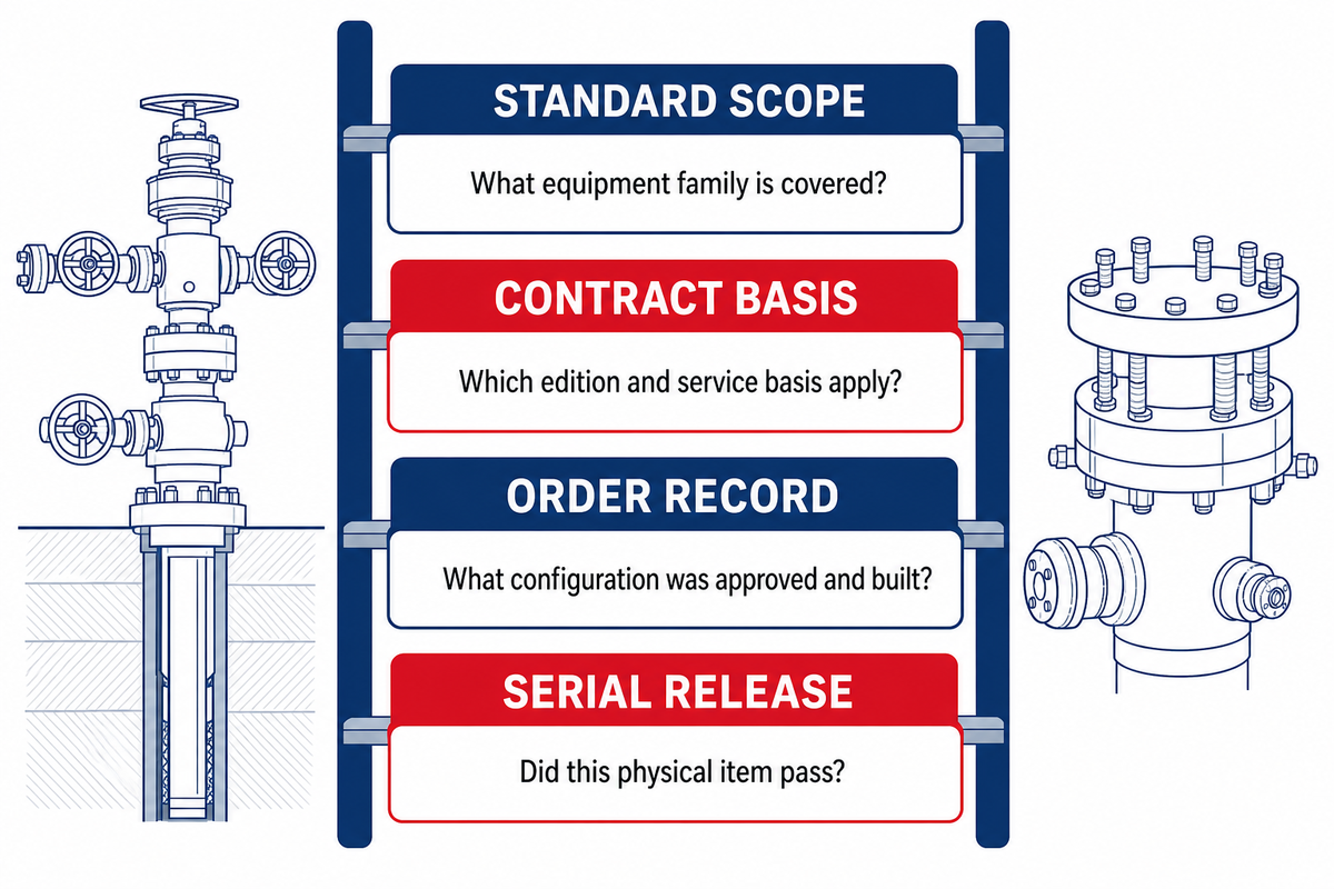
API Spec 6A and ISO 10423 define product-standard scope for wellhead and tree equipment, but public scope pages do not approve a specific configuration or serial number. The contract must identify the applicable edition, rating, material/service basis, product-level obligations and project interfaces; order records must then prove what was supplied.
The public page for API’s specification 6A, 21st Edition, details changes concerning wellhead and tree product lines, hangers, tubing-head adapters, pressure-boundary qualification, records and marking. API’s update index shows when addenda and errata were dated, including changes for 2024. ISO identifies ISO 10423:2022 as Edition 5 for wellhead and tree equipment. These pages establish currency and scope; they do not expose every normative clause, provide a project design basis or certify a supplier’s exact unit. .
| Evidence | Can prove | Cannot prove alone |
|---|---|---|
| Public API/ISO scope page | Standard identity, title, edition and public scope | Quoted design compliance or serial acceptance |
| Company quality certificate | Audited management-system scope on the certificate | That every product meets API 6A |
| Facility or license record | Named site and licensed scope at the checked date | Exact offered configuration or order contents |
| Design-family qualification | A defined design was qualified within stated boundaries | That the offered bill of materials matches it |
| Order and serial records | What was built, inspected, tested and released | Fitness outside the approved design basis |
Consider jurisdiction. The referenced U.S. offshore regulation requires applicable wellhead, tree and related equipment to be designed and tested to API 6A or API 17D and to exceed the maximum anticipated surface pressure, but it applies within that regulatory context. It shouldn’t be extrapolated into a global field-installation procedure . For a broader explanation of the standards boundary, use the wellhead and well-control guide.
Scope boundary: ISO 10423:2022 covers wellhead and tree equipment requirements, but its public scope excludes field use, field testing and general field repair. Product-standard conformance is therefore not an installation or repair procedure.
Build the Four-Packet Technical Requisition
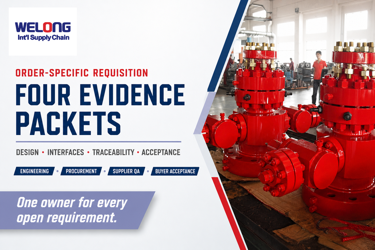
The Four-Packet Technical Requisition separates design-basis, interface-control, manufacturing-traceability and final-acceptance evidence. That separation means a supplier badge or generic catalog can’t be relied upon as proof of the ordered configuration, while giving the engineering, procurement and quality teams an owner for each of the open requirements.
| Packet | Minimum contents | Owner | Decision unlocked |
|---|---|---|---|
| 1. Design basis | Well architecture, string programs, loads, pressures, temperatures, fluids, service and applicable requirements | Project/completion engineering | Which design envelope must be met |
| 2. Interface control | Stack drawing, bowl/hanger profiles, seals, bores, drifts, outlets, penetrations and mating connections | Interface owner plus supplier engineering | Whether every handoff is geometrically and functionally closed |
| 3. Manufacturing traceability | Approved BOM, material traceability, procedures, qualification references, inspection plan and marking | Supplier QA and buyer QA | Whether the offered and built unit match the approved family |
| 4. Final acceptance | Order-specific inspection, test, nonconformance closure, release and serial dossier | Supplier QC and buyer acceptance authority | Whether the specific unit may ship and be received |
‘Project-defined’ in the table is intentional. Controlled project inputs and manufacturer procedures must supply the values, and the interface record should state unresolved deviations rather than borrow a generic number.
Interface checklist — copy these into your verification request:
| Parameter | Recommended range | Why it matters | How to verify |
|---|---|---|---|
| String and hanger schedule | Project-defined | Controls bowls, load shoulders and seals | Approved well and stack drawings |
| Pressure and temperature cases | Project-defined | Controls ratings and qualification boundaries | Design-basis memorandum |
| Fluid and material service | Project-defined | Controls materials and seal compatibility | Fluid analysis and material specification |
| Lower and upper interfaces | Exact controlled geometry | Prevents false flange-only compatibility | Interface-control drawing |
| Product-level obligations | Contract-defined | Controls qualification, inspection and records | Purchase specification and deviation list |
| Inspection and test basis | Procedure-defined | Defines witness and acceptance points | Approved ITP and test procedure |
| Serial dossier | One package per released unit | Ties acceptance to the physical item | Serial numbers, release note and manufacturing record book |
For product configurations, supply options, or quotation requests, continue to the existing casing head and tubing head solutions page. This guide remains limited to engineering definitions, interfaces, and verification records.
Five Installation Hold Points Before Pressure Is Applied
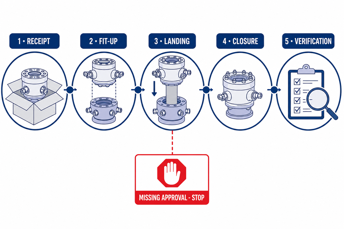
Use five witnessable hold points: condition of receipt, interface fit, hanger landing, closure of pressure boundary and staged verification. At each point, stop if the approved drawing, manufacturer procedure, acceptance value or responsible witness is missing. Remote invention of generic torque, cut-off height, test pressure and hold time isn’t allowed.
| Hold point | Verify | Evidence retained | Stop when |
|---|---|---|---|
| 1. Receipt | Identity, serial, protection, damage, cleanliness and document match | Receiving inspection and photographs | Identity or condition is unresolved |
| 2. Fit-up | Preparation, flange faces, ring grooves, bore, orientation and alignment | Fit-up checklist and measured condition | Mating geometry or preparation differs |
| 3. Landing | Hanger identity, landing position, load transfer and seal interfaces | Landing record and witness sign-off | Landing indication or load path is uncertain |
| 4. Closure | Seals, lockdown, outlets, valves, penetrations and adjacent connections | Assembly record against approved procedure | A barrier component or procedure step is missing |
| 5. Verification | Approved test medium, stages, limits, hold time, monitoring and acceptance | Calibrated test record and disposition | Values or acceptance authority are not approved |
How is a casing head installed?
A casing head is installed against a specific lower preparation and approved manufacturer procedure, then checked for orientation, alignment, hanger and seal interfaces before the pressure boundary is closed. The weld, thread or slip-on method, along with dimensions, torque, test pressure and hold time, is defined by the controlled design and procedure. A safe guide may define the verification sequence; it doesn’t replace qualified personnel, the well program or the manufacturer’s instructions.
Some designs are threaded onto the prepared connection, whereas others are threaded or welded onto the supporting casing under a qualified procedure. Cutting casing to height and preparing the end are controlled field operations, not details to be copied from a generic illustration. The approved method must define inspection before the next body is landed.
Installation evidence matters because a component can be correctly manufactured and still be assembled against the wrong preparation or seal condition. A published study of a casing-head support-ring problem illustrates how local geometry, contact and load transfer can become the governing issue; it doesn’t create a universal repair or landing rule . For pressure-control context, keep the separate BOP function and testing guide available to the installation team.
That support-ring study reported an initial model with 895 MPa average shear stress under an 870-tonne modeled load, then evaluated an optimized geometry against its own working and engineering-test cases. Those numbers belong to that modeled design, not to a field load limit. A separate tubing-hanger connector case described more than 50 prototype tests and an 18-month qualification program; again, the evidence shows how configuration-specific qualification can be, not a universal minimum test count .
Scenario – Damage to ring groove found at fit-up. The flange label, pressure class and bolt pattern all match, but receipt photographs show a local ring-groove defect. The five-hold-point method stops the installation before closure. The team records the location and extent, protects the surface, checks the order drawing and acceptance criteria, and routes the finding to the named engineering authority. The team doesn’t dress the ring groove, substitute a ring, or infer repairability from appearance. That sequence preserves both the pressure-boundary evidence and the supplier’s ability to issue a configuration-specific disposition.
Eight Interface Failure Signals and What to Check Next
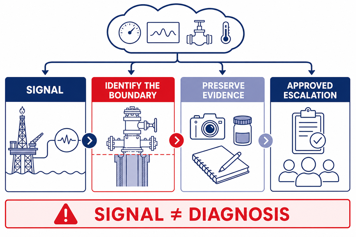
A leak, abnormal annulus pressure, or landing problem is a signal, not a diagnosis. First, ascertain the affected pressure boundary and operating state. Then investigate seal history, hanger position, groove condition, alignment, outlets, connections, and records. Isolate and escalate under an approved integrity procedure. Don’t prescribe a remote repair.
| Signal | Possible interface to investigate | Check next | Do not infer |
|---|---|---|---|
| External flange leakage | Flange, gasket/ring groove, bolting or alignment | Location, pressure state, assembly and test records | That tightening is the safe correction |
| Unexpected annulus pressure | Tubing, hanger seal, casing barrier or outlet path | Pressure trend, communication tests and barrier schematic | Which barrier failed from pressure alone |
| Pressure will not hold | Open valve, test boundary, seal or connection | Test setup, calibrated instruments and isolation map | A component defect before setup review |
| Hanger fails to land | Bowl profile, debris, alignment or wrong hanger | Identity, clean condition, landing dimensions and procedure | That forcing or machining is permitted |
| Seal cannot energize | Seal identity, preparation, tolerance or installation sequence | BOM, seal record and controlled procedure | Universal energization travel or torque |
| Outlet reads the wrong pressure | Port routing, valve lineup or internal communication | Drawing, tagging and annulus map | The label proves communication |
| Abnormal movement or settlement | Load shoulder, support, hanger or structural path | Baseline position, load history and engineering inspection | Safe continued operation |
| Corrosion or damaged groove | Pressure-containing surface and seal contact | Extent, material, service exposure and acceptance criteria | Repairability from appearance alone |
A PNAS study reported 15,130 of 105,031 tested wells meeting its surface-casing-vent-flow or sustained-casing-pressure criteria, or 14.4%, but that’s a whole-well integrity finding with jurisdiction, test-selection and method caveats. It isn’t a casing-head failure rate and must not be used to estimate component reliability . The practical lesson is to preserve pressure history and barrier evidence so an anomaly can be routed to the right interface.
Scenario – annulus pressure occurs after stable operations. The operator first confirms the gauge, valve lineup, monitored annulus and operating state. The team then preserves the pressure trend and barrier schematic. If pressure communication is suspected, the team follows the approved integrity program to isolate and test the relevant boundaries. It does not label the tubing-head seal as failed from one reading or use the 14.4% study result as a component probability. The decision record should state which boundary was tested, which evidence changed the diagnosis, and who authorized the next intervention.
Gas wells and injection wells may have different operating histories, but neither label diagnoses an interface failure. The integrity review should identify whether the casing head forms the observed boundary, then test that hypothesis against the drawing, pressure history and inspection evidence.
Can a casing head be repaired in the field?
Only an authorized engineering disposition can answer that for a specific component and defect. The decision depends on pressure-boundary function, material, damage mechanism, extent, accessibility, applicable code or standard, manufacturer limits and the approved repair or qualification route. It isn’t acceptable to machine a bowl, dress a ring groove, weld a pressure-containing body, or substitute a seal based on a generic article. Stabilize the well, preserve evidence and escalate through the integrity-management process.
Supplier Evidence Ladder: Certificate to Serial Number
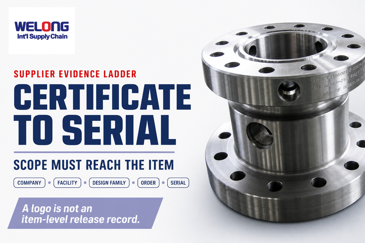
Supplier evidence has five levels: company management system, manufacturing facility, qualified design family, customer order and serial-number acceptance. Each level answers a different question. A broad certificate can support organizational capability, but only order and serial records tie the approved configuration, inspection and test results to the item received.
| Level | Buyer question | Useful evidence | Gap if used alone |
|---|---|---|---|
| 1. Company | Is there an audited quality system? | Current certificate with scope and issuing body | No product-specific proof |
| 2. Facility | Which site performs the controlled work? | Facility scope, licenses and audit records | No proof of the quoted design |
| 3. Design family | Was this configuration family qualified? | Qualification basis, boundaries and approved drawings | No proof the order matches |
| 4. Order | What did the buyer approve and the supplier build? | PO, deviations, BOM, ITP and manufacturing records | May not close serial acceptance |
| 5. Serial | Did this physical item pass its required checks? | Serial trace, inspection/test reports and release | Does not expand the approved service envelope |
Ask for scope, date, facility and configuration rather than collect logos. API’s public update index and specification pages are useful routes for checking edition currency, but a public listing is not a manufacturing record book. User-supplied company materials describe China Welong, founded in 2001, as an international integrated supply-chain service provider. User-supplied company materials reference ISO 9001:2015 and API 7-1; that reference does not establish an API Monogram licence or API 6A casing-head or tubing-head product conformance. Buyers should verify current organization and facility scope, then reconcile it with the project requisition, design family, deviations and serial dossier.
What Changes, and What Stays Project-Specific
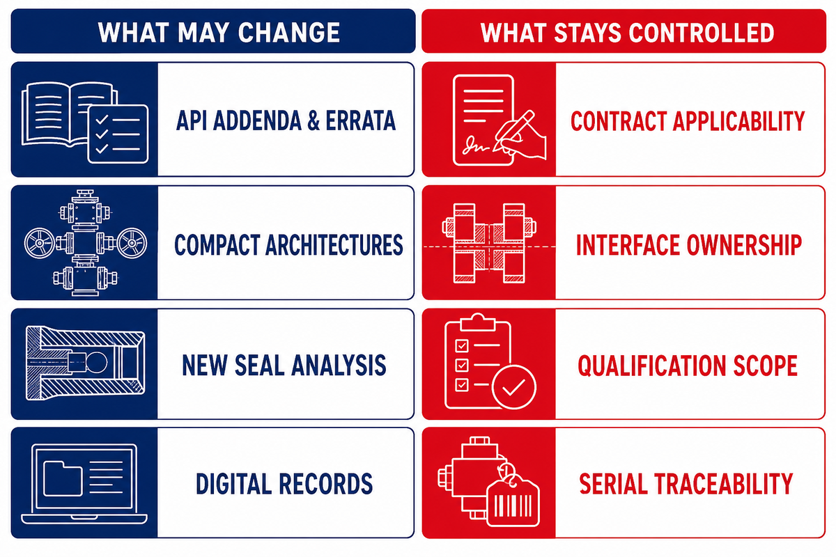
Editions, addenda, available seal technology and integrity evidence change over time. The constant is that every claim is to be checked against the applicable contract, jurisdiction, design family and serial record. New terminology or a later catalog can’t change an approved pressure boundary or field procedure.
Use API’s amendment and errata index as an edition check, then preserve the contract’s recorded applicability basis instead of silently substituting a later publication.
| Changing evidence | Stable principle | Buyer action |
|---|---|---|
| API addenda and errata | Contract applicability controls | Record the edition and update basis in the requisition |
| Compact and unitized architectures | Every interface function still needs an owner | Request a function-to-body and barrier map |
| New seal analyses and materials | Qualification scope remains configuration-specific | Compare the proposed design with its qualified boundary |
| Digital records and verification portals | Traceability must reach the physical serial item | Preserve the checked record and date with the dossier |
This isn’t a market forecast. DataForSEO showed a mixed product/reference result set and no tool sites among the five visible organic results. The article is designed to address informational long-tail questions and to help qualified visits to the commercial owner, not to displace the solution page for quotation intent.
Frequently Asked Questions
What is a casing head?
A casing head is the lower pressure-containing wellhead body attached to or supported from the surface casing. Its bowl accepts a casing hanger for the next string, while its seals and side outlets isolate and access the relevant casing annulus. The name alone doesn’t establish the hanger, lower preparation, seal profile, outlet arrangement or pressure class.
What is a tubing head?
A tubing head sits above the casing-head or casing-spool section and houses the tubing hanger that suspends production tubing. It contains and provides access to the tubing-to-production-casing annulus and transitions toward the tree. Bore profile, seal arrangement, penetrations and mating geometry must still be confirmed from the approved stack design.
Are casing heads and tubing heads the same?
No. A casing head supports a casing string and manages a casing-to-casing annulus near the lower wellhead. A tubing head supports the production-tubing hanger and manages the tubing-to-production-casing annulus higher in the stack. Because compact systems can combine functions, the stack drawing and interface schedule, not the label or housing count alone, should control selection.
What pressure rating should I choose for a casing head?
Use the rating established by the approved well design and governing pressure case. Confirm temperature, material class, service conditions, load combinations, mating connections and test basis at the same time. A higher catalog pressure number isn’t an independent compatibility decision and can’t compensate for a weaker adjacent component or unverified seal interface.
How is a tubing head connected to the Christmas tree?
The upper interface commonly transitions through the tubing-head top flange and a tubing-head adapter to the tree, but that describes architecture, not approval. Review the mating size and rating, flange and ring-groove details, bore and drift, tubing-hanger neck or seal-bore relationship, lockdown arrangement, control-line penetrations and any crossover in geometry. The stack drawing must show which component owns each pressure boundary and which installation step closes it.
How long does a casing head last?
There’s no universal service-life number. Condition depends on service environment, load and pressure history, materials, corrosion, maintenance, inspection findings and the manufacturer’s acceptance criteria. Use documented inspection and engineering disposition rather than age alone.
References & Sources
- Specification 6A public announcement American Petroleum Institute
- API Monogram and APIQR latest updates American Petroleum Institute
- ISO 10423:2022 scope page International Organization for Standardization
- 30 CFR 250.518 U.S. Electronic Code of Federal Regulations
- Surface casing vent flow and sustained casing pressure study Proceedings of the National Academy of Sciences
- Casing-head metal seal study Lubricants
- Casing-head support-ring analysis PubMed Central
- Unitized wellhead case OnePetro
Bring the interface package, not just a size and pressure class, to configuration approval
Prepare the 12 inputs and four evidence packets first. The approved configuration boundary can then be reviewed against named owners and controlled records.