Get in touch with Welong Company

Updated September 2026
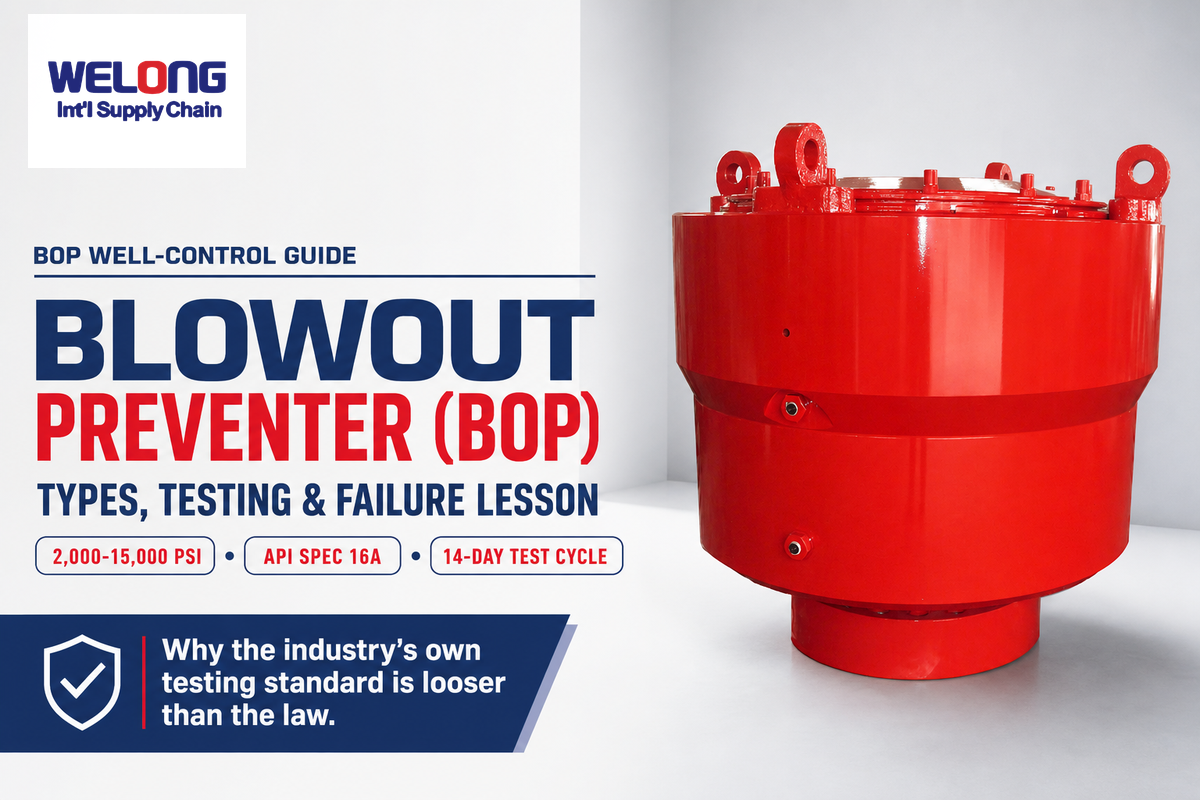
A blowout preventer (BOP) is the last mechanical barrier between a controlled well and an uncontrolled one. Welong’s own API 16A product line, for instance, spans a working-pressure range of 2,000–15,000 psi with annular bores from 9″ to 21-1/4″ and ram bores from 7-1/16″ to 21-1/4″†, numbers that map directly onto the API 16A pressure classes every BOP on a rig is built to. This guide covers what a blowout preventer is, how it actually works, why federal regulation is actually stricter than the industry’s own testing standard, and the single historical failure that rewrote how the oil and gas industry tests these systems.
Quick Specs
| Working pressure range | 2,000–15,000 psi (13.8–103.4 MPa) |
| Annular bore range | 9″–21-1/4″ |
| Ram bore range | 7-1/16″–21-1/4″ |
| Governing standard | API Spec 16A (drill-through equipment) |
| Federal pressure-test interval | Every 14 days (30 CFR 250.737) |
| Sour-service rating | NACE MR0175 |
What Is a Blowout Preventer?
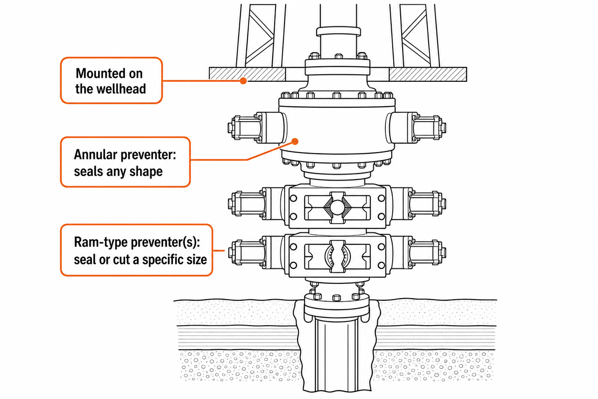
A blowout preventer (BOP) is a stack of hydraulically actuated valves mounted on the wellhead that seals the wellbore when formation pressure exceeds the drilling fluid’s ability to hold it back. It sits between the rig floor and the reservoir and is built to do one job well: close fast, under pressure, without depending on anything above it still working.
Search “bop blowout preventer” and most people are trying to confirm exactly this, that BOP is simply the acronym, not a different piece of equipment. The device isn’t a single valve. It’s a blowout preventer stack: several individual preventers’ worth of engineering compressed into one assembly, typically an annular blowout preventer on top and one or more ram-type preventers below it. Each one covers a different failure mode. An annular preventer can seal around almost any shape in the hole (a drill pipe, a tool joint, or nothing at all); rams seal around a specific pipe size or, in an emergency, cut through the pipe entirely. Which combination is installed, and how it’s rated, is governed by API Spec 16A, the American Petroleum Institute’s drill-through-equipment standard (see BSEE’s standards overview for how it fits alongside API 6A and 16C) — a distinct standard from the API 6A wellhead/tree hardware sitting beneath it. Understanding the importance of a blowout preventer starts with recognizing that it’s the one component in the whole system that has to work when everything else has already gone wrong.
How a Blowout Preventer Works, From Kick to Shut-In
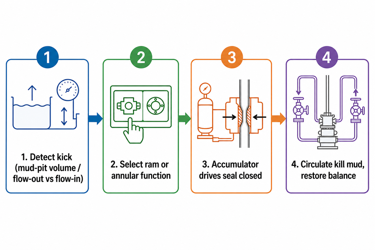
A blowout starts as a kick: formation fluid, oil, natural gas, or both, enters the wellbore because its pressure momentarily exceeds the hydrostatic pressure of the drilling mud column holding it back. Left unmanaged, that fluid displaces mud, reduces the column’s weight further, and the well pressure imbalance compounds, which is why response time, not just equipment quality, decides the outcome during ordinary drilling operations on any oil well.
How Does a Blowout Preventer Work?
The crew identifies the kick from a rise in mud pit volume or a change in flow-out versus flow-in, selects the correct ram or annular function from the control panel, and hydraulic pressure from a charged accumulator bank drives the sealing element closed around the pipe, or through it if a shear ram is selected. The crew then circulates heavier “kill” mud through the choke and kill lines to restore hydrostatic balance before reopening the well.
The control panel itself is normally controlled from the rig floor, giving the crew direct hands-on access to every function in the sequence above. The entire sequence works even if the rig loses primary power, accumulators store enough hydraulic energy to close the stack once without external electricity. That’s blowout preventer how it works in outline; the specific timing and pressure margins vary by stack and well, which is exactly what the sections below cover. The regulatory framework behind that function, what counts as a validated BOP control response, is set out under API Spec 16A, the drill-through-equipment validation-testing standard BSEE references for offshore operators.
Choosing Between an Annular BOP and a Ram BOP
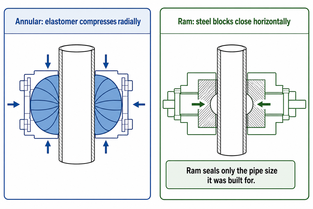
One annular BOP element uses a single doughnut-shaped elastomer that squeezes shut around whatever is in the hole, drill pipe of any size, tool joints, or open hole. By contrast, a ram preventer uses a matched pair of steel blocks that close horizontally to a fixed diameter; it seals tighter and holds higher pressure than an annular element, but only around the pipe size it was built for. Ram types (pipe, blind, and shear) aren’t interchangeable, which is the single most common source of confusion for anyone new to reading a stack diagram. In practice the choice isn’t either/or: nearly every real API 16A stack pairs one annular (broad, lower-pressure sealing) with one or more rams (size-specific, higher-pressure sealing) rather than relying on a single type alone.
| Feature | Annular BOP | Ram BOP |
|---|---|---|
| Sealing method | Elastomer element compresses radially | Two steel blocks close horizontally |
| Size range sealed | Any size up to bore diameter, including open hole | One specific pipe OD per ram set (pipe/variable-bore ram) or none (blind ram) |
| Can cut pipe? | No | Only the shear ram, and only within its rated pipe OD/wall thickness |
| Typical stack position | Top of stack, first line of defense | Below the annular, in a fixed sequence |
| Limitation | A matched ram at that bore holds higher working pressure | Useless against a pipe OD it wasn’t built for — not universal |
Can a Shear Ram Cut Any Drill Pipe?
No. Every shear ram is rated to a specific pipe outside diameter and wall thickness/grade combination; it’s a common procurement mistake to assume a shear ram is a universal cutting tool. If the string in the hole falls outside that rating (a heavier-wall drill collar, a tool joint upset, or dual-string completion tubing), the shear ram may not fully sever and seal it. Matching shear-ram rating to the string design is a selection step, not an afterthought.
Inside the BOP Stack, Components and Control System
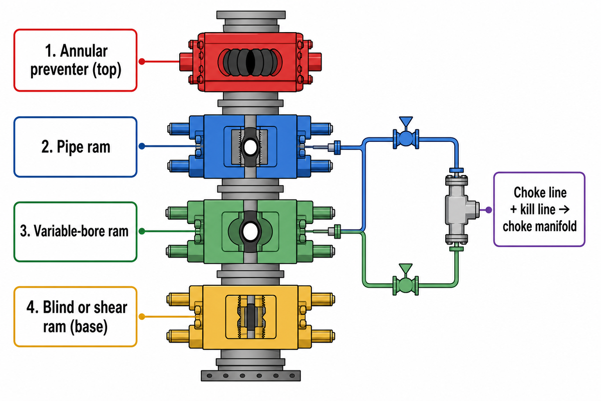
The bop stack components, read from the top of the bop stack down, are: an annular preventer, then one or more ram preventers in a fixed order, typically a pipe ram, then a second pipe or variable-bore ram, then a blind or shear ram at the bottom, plumbed into a choke line and a kill line, run through rated choke and kill hose, that let the crew circulate under pressure once the well is shut in; the two together are often called the kill and choke lines, and they terminate at a choke manifold where flow is actually metered and controlled. None of it moves without the control unit: a hydraulic power unit, control valves, and an accumulator bank holding pressurized hydraulic fluid, sized to close every function in the stack at least once even if rig power is lost. Electrical and hydraulic lines run from the control unit to each ram and to the annular, and the casing string run in the well below the stack has to be accounted for when the crew selects which ram to close, the ram’s bore has to match the casing or drill-pipe OD actually in the hole at that depth.
| Type | Function | Typical stack position |
|---|---|---|
| Annular preventer | Seals around any shape via elastomer compression | Top of stack |
| Pipe ram | Seals around one specific pipe OD | Upper ram position |
| Variable-bore ram | Seals across a narrow range of pipe ODs | Upper or middle ram position |
| Blind ram | Seals the wellbore with no pipe present | Lower ram position |
| Shear ram | Cuts the drill string and seals, within its rated OD/grade | Base of stack |
| Cameron-type ram | Ram mechanism per the original 1926 patent lineage | Any ram position, by manufacturer design |
| Hydril-type / Shaffer-type | Competing ram and annular mechanisms, same function class | Any position, by manufacturer design |
| Control unit / accumulator | Stores hydraulic power to close every function at least once | Adjacent to stack, rig floor or skid |
| Choke manifold | Meters and controls flow after shut-in | Downstream of choke/kill lines |
Three API standards govern this system, and they aren’t interchangeable labels for the same thing. API Spec 6A covers the wellhead and tree hardware the stack sits on. API Spec 16A covers the drill-through equipment, the BOP stack itself, including its design validation and testing. API Spec 16C covers the choke-and-kill system that lets the crew control pressure once the well is sealed. Building a stack to spec means all three apply to different physical hardware in the same well-control chain, and conflating them is a common source of confusion when reading a quote or a spec sheet. Getting the bop configuration right before bop installation, not after crews already have to make up a bop stack on the rig floor under time pressure, is what this standards split is actually protecting against.
Where the Type Names Come From, Cameron, Hydril, Shaffer
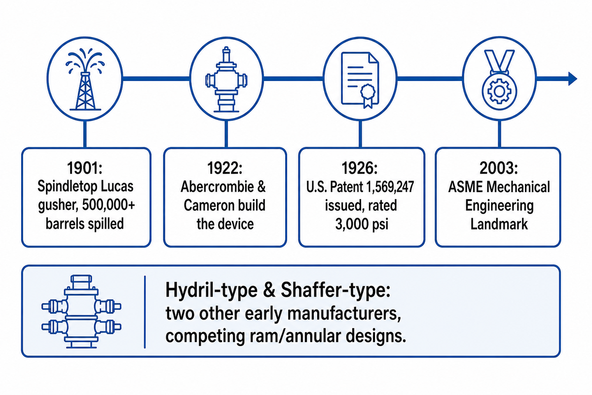
The ram-type BOP exists because of a specific, dated invention. In 1922, James S. Abercrombie and Harry S. Cameron, who had founded Cameron Iron Works two years earlier, built a device to solve exactly the problem that made the 1901 Lucas gusher at Spindletop, Texas, run uncontrolled for over nine days and spill more than 500,000 barrels: nothing existed that could close around a drill string under pressure.
Their design, tested to withstand 3,000 psi at the time, was issued U.S. Patent 1,569,247 on January 12, 1926, and was later designated an ASME Mechanical Engineering Landmark in 2003.
“Hydril-type” and “Shaffer-type” trace to two other early manufacturers who developed competing ram and annular designs in the following decades; the names persisted as generic descriptors for the mechanism even after the companies themselves were absorbed into larger oilfield-equipment groups. Knowing the lineage matters less for buying a BOP than for reading older equipment manuals and inspection records, where a “type” designation is still how a rig crew identifies which control-system logic and ram geometry they’re working with, and, on an inherited or secondhand stack, for correctly identifying the components of a blowout preventer before assuming any two “rams” are interchangeable.
Surface vs Subsea BOP Stacks, The Deployment Decision Matrix
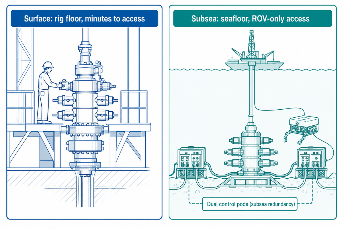
A surface stack sits on the wellhead at the rig floor, where the crew can see it, function-test it by hand, and reach it in minutes. By contrast, a typical subsea deepwater blowout preventer sits on the seafloor, sometimes thousands of feet below the rig, connected only through a marine riser and an electro-hydraulic control umbilical, which means every design decision has to account for the fact that nobody can walk up and manually intervene.
| Factor | Surface stack | Subsea stack |
|---|---|---|
| Typical application | Land rigs, platform/jack-up wells | Floating rigs over deepwater wells |
| Access for manual intervention | Direct, minutes | None — ROV-only, hours at best |
| Control redundancy | Single control panel plus manual override | Dual control pods (electro-hydraulic multiplex) so one pod failure doesn’t strand the stack |
| Riser/marine connection | None | Marine riser links stack to rig; adds a failure path the surface case doesn’t have |
| Limitation | Not rated for the pressure/redundancy demands of deepwater columns | Higher capital cost and longer lead time; not justified for wells that don’t need it |
The redundant control pods on a subsea stack exist for a simple reason: a control-system fault that would be a same-day repair on a surface rig becomes a multi-day, ROV-dependent recovery on the seafloor, so the design has to tolerate a single pod failure without losing the ability to close the well. Global offshore activity is a relevant backdrop here: one market analysis projects the blowout preventer market to grow from roughly $35.73 billion in 2025 to $37.51 billion in 2026, citing ultra-high-pressure (15,000+ psi) subsea stacks as one of the fastest-growing segments, consistent with deeper water and higher-pressure reservoirs driving demand for exactly this configuration.
BOP Testing and Maintenance, The Testing-Gap Triangle
Every BOP on a working well gets tested on a schedule, because pressure control equipment is only as good as its last verified test. What’s rarely explained is that the schedule itself has a documented gap between what the industry’s own standard requires and what federal regulation actually mandates, and that gap is a useful lens for understanding why a “tested” BOP can still fail. Blowout preventers are critical enough to well control that operating the blowout preventers correctly is treated as a distinct, auditable discipline, separate from simply owning the right hardware.
API Standard 53, the industry’s own recommended practice, specifies a 21-day pressure-test interval, per BSEE’s own research on the test-interval question. But the binding federal regulation is stricter: 30 CFR 250.737 requires a full pressure test at least every 14 days (30 days specifically for the blind shear ram), function testing of the annular and pipe/variable-bore rams every 7 days between pressure tests, and function testing of shear rams every 14 days, each pressure test held for 5 minutes on a subsea system or 3 minutes on a surface system with a recorded chart. In other words, the regulation that actually binds operators is tighter than the standard the industry wrote for itself, not the other way around, a detail that rarely makes it into a buyer’s guide.
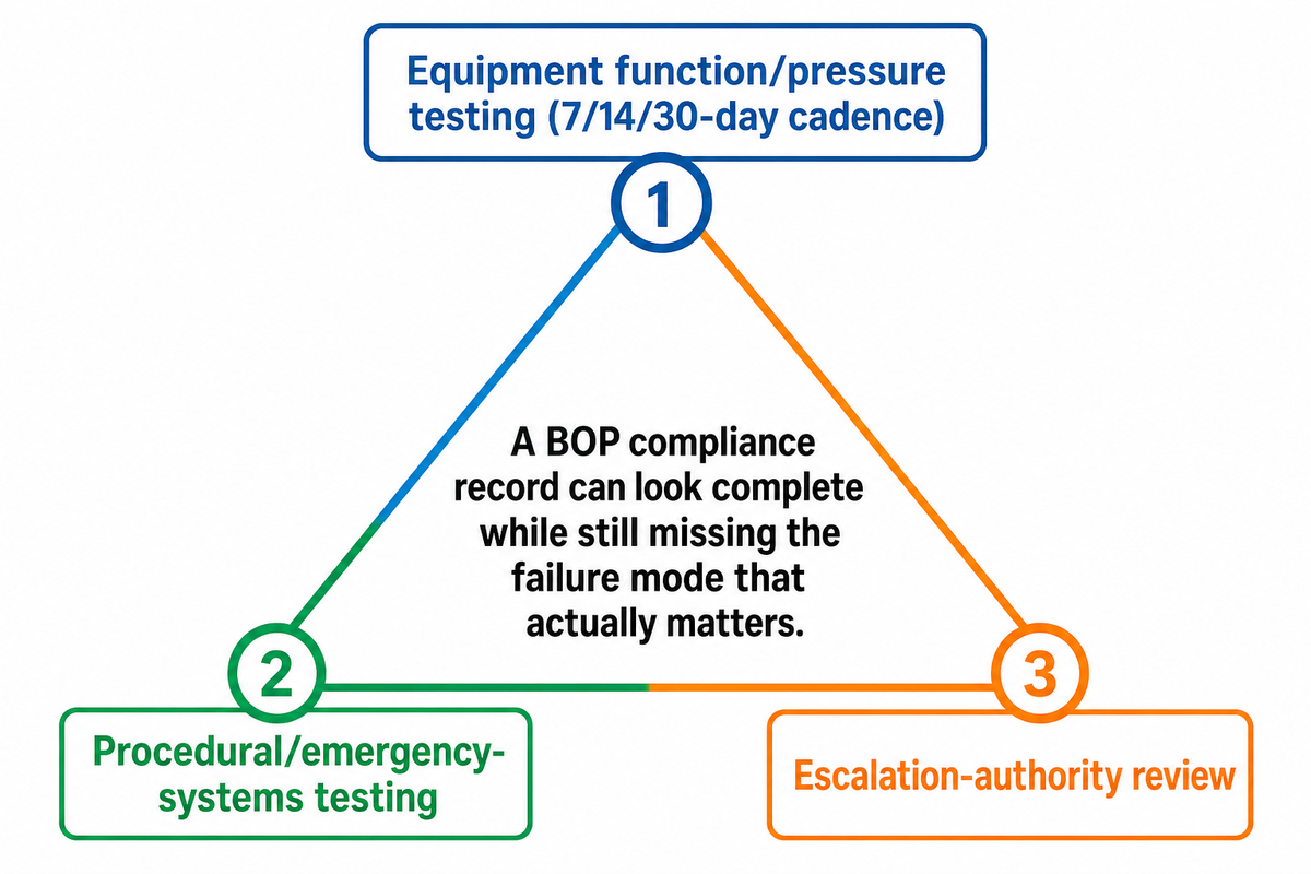
The 3-Point Testing-Gap Triangle
A BOP compliance record can look complete while still missing the failure mode that actually matters. Three separate things have to be checked, and a program that only covers one or two of them isn’t actually “fully tested”:
- Equipment function/pressure testing, the 7/14/30-day cadence above. This is the layer everyone checks, because it’s the layer that’s written into a regulation with a clear violation trigger.
- Procedural/emergency-systems testing, verifying the systems that only activate in a genuine emergency (deadman/autoshear logic, backup power cutover), not just the day-to-day functions crews exercise routinely.
- Escalation-authority review, whether the crew and management chain actually has a tested, rehearsed path to authorize and execute a shut-in decision under pressure, not just equipment that’s capable of it.
How Do I Choose the Correct BOP Pressure Rating?
Size the rated working pressure to the well’s maximum anticipated surface pressure, not just the BOP’s own nameplate rating, a distinction API Standard 53’s fifth edition (2020) reportedly made when it shifted the basis of BOP requirements from equipment-rated to well-specific anticipated surface pressure. A stack rated for 10,000 psi on a well whose kick tolerance could realistically produce a higher surface pressure is undersized on paper, even if it passes every routine function test.
The Testing-Gap Triangle isn’t a hypothetical framework. It’s a direct reading of the best-documented BOP failure in history, covered next, where layer 1 was in place and layers 2 and 3 weren’t.
When BOPs Fail, The Deepwater Horizon Lesson
On April 20, 2010, the Deepwater Horizon’s blowout preventer failed to seal the Macondo well, leading to an uncontrolled release of crude oil and a sustained flow of oil and gas into the Gulf of Mexico. The U.S. Chemical Safety Board’s final report found a specific, narrow technical cause: an unrecognized pipe-buckling phenomenon during the emergency well-control effort, a failure of the bop that turned a well-control incident into the worst offshore spill in U.S. history.
That single mechanical finding gets most of the attention, but the CSB’s broader conclusion is the one that maps directly onto the Testing-Gap Triangle: Deepwater Horizon personnel did regularly test the day-to-day BOP components needed for drilling, layer 1 was functioning, but neither Transocean nor BP had regularly inspected or tested the BOP’s emergency systems, and the CSB’s recommendation was for API to revise Standard 53 for organizational and testing reasons, not purely a hardware fix.
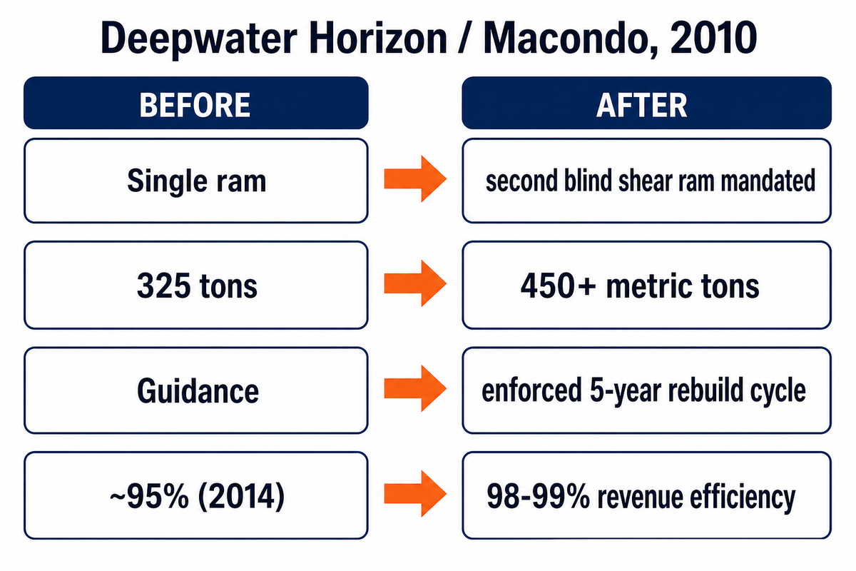
The industry’s response bears that out. Following the Macondo blind-shear-ram failure, regulators mandated a second blind shear ram on subsea stacks for redundancy, where a single blind shear ram had stood before; stack weights grew from roughly 325 tons to 450-plus metric tons to accommodate the added accumulator capacity a second shear ram demands; and API Standard 53 maintenance shifted from guidance to an enforced requirement that a BOP control system be broken down and rebuilt on a 5-year cycle. Reported revenue efficiency improved from around 95% in 2014 to 98–99% in recent reporting, a real, measurable gain.
What hasn’t changed is more instructive. One decade after Macondo, more fundamentally different BOP designs, all-electric actuation instead of hydraulic, for instance, have been proposed but, per SPE’s Journal of Petroleum Technology, none has been tested on a working drilling rig. The barrier isn’t unresolved engineering; it’s economic and behavioral. As ESD CEO John Dale has put it, manufacturers’ service revenue is built on hydraulic parts and maintenance, not one-time hardware sales, which blunts the incentive to obsolete that revenue stream, a notable admission from an executive whose own company sells an all-electric alternative; and operators are reluctant to be first to deploy an unproven control architecture.
“Consequences of failure are very high.”
Darrell Pelley, Transocean, on why operators hesitate to be first to deploy an unproven BOP control architecture (quoted in SPE’s Journal of Petroleum Technology)
That’s a genuinely counter-intuitive finding: the constraint on the next generation of well-control equipment is less about what engineers can build than about who’s willing to be the first to run it.
⚠ When a BOP Is Not Enough
A BOP is the last mechanical barrier, not the only one. It can’t compensate for a kick that goes undetected because a crew misreads mud-return anomalies as “ballooning” — a real, documented misdiagnosis pattern where crews pattern-match a kick to a prior well’s behavior instead of confirming it with fingerprinting or flow analysis. Nor can it substitute for the primary barrier: correctly weighted drilling fluid. Even a BOP that closes correctly on a well where the kick was misdiagnosed for hours beforehand is still closing too late to prevent the underlying loss of control that made the closure necessary in the first place, the release of oil or gas at that point is a consequence of the delay, not of the hardware.
Who Is Qualified to Test and Operate a BOP
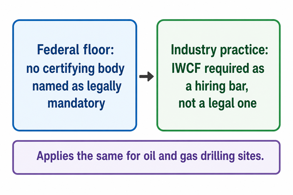
The federal regulatory floor is lower here than most buyers assume. 30 CFR 250.1505 doesn’t name IWCF, IADC, or any specific certifying body as legally mandatory, it requires only that personnel training come from a source that meets the operator’s own approved training plan. That floor applies the same way regardless of whether the well is a gas or an oil drilling site; the regulation doesn’t set a different bar by hydrocarbon type.
In practice, the industry has converged on a de-facto standard anyway: most operators require IWCF certification or an equivalent as a contractual hiring bar even though no federal rule compels it directly, which means “certified” on a resume is an operator requirement, not strictly a legal one. For the full IWCF Level 2 through Level 4 hour and validity breakdown, see our Wellhead & Well Control guide; the requirement is worth confirming against the specific operator’s own training plan rather than assuming it’s interchangeable across employers.
BOP Standards at a Glance
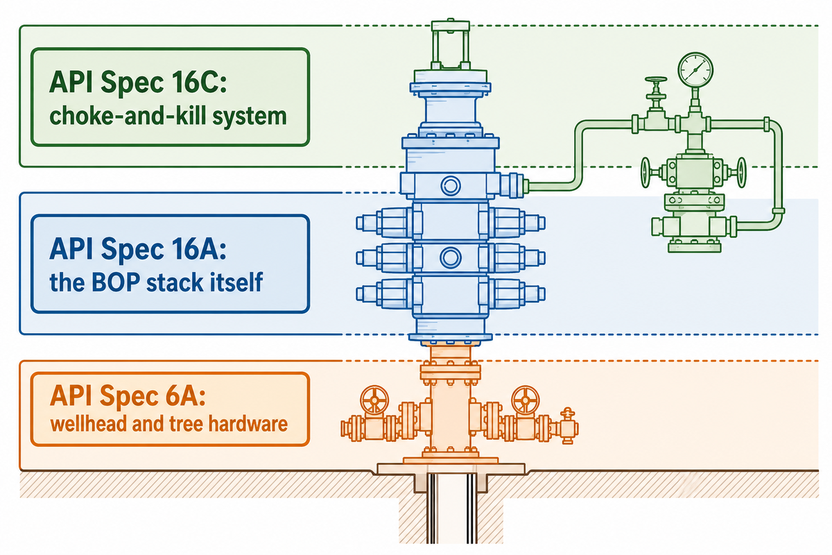
Three API specifications get cited interchangeably in casual conversation but govern different equipment: API 6A (wellhead and tree equipment), API 16A (the BOP stack itself, drill-through equipment and its validation testing), and API 16C (the choke-and-kill system). Look inside BOP procurement paperwork and expect all three standards to appear on different line items; a ram blowout preventer or annular blowout preventer uses API 16A, a full blowout preventer control system references API 16D, and the surrounding wellhead hardware sits under API 6A; different BOP components are simply not certified under one blanket document, on oil and gas wells anywhere in the world.
Integration & Utility Requirements
| Hydraulic power unit | Sized to close every stack function at least once on accumulator reserve alone, independent of rig power |
| Control-line routing | Choke and kill lines rated to the same working pressure as the stack, not a lower “convenience” rating |
| Governing spec at RFQ stage | Confirm API 16A pressure class, bore size, and NACE MR0175 sour rating against the well’s own kick-tolerance data before quoting |
For teams ready to move from understanding these standards to specifying hardware against them, Welong’s API 16A BOP product line lists the annular and ram configurations, pressure classes, and Cameron/Hydril/Shaffer-type compatibility referenced throughout this guide, along with the procurement documentation each order requires.
Frequently Asked Questions
Q: What Is a BOP Stack?
A BOP stack is the full assembly of preventers, typically an annular preventer plus multiple ram-type preventers, installed together on the wellhead, along with the choke and kill lines and the control system that operates them.
The stack is arranged in a fixed order so that if one element fails to seal, the next one in the sequence still can. A typical land or platform blowout preventer system runs an annular on top, a pipe ram below it, and a blind or shear ram at the base as its core bop units, each covering a different well-control scenario, from an open hole to a full pipe cut, and able to close off the well entirely if it produces oil or natural gas faster than the crew can manage it.
Q: What Are the Two Main Types of BOP?
The two main types are annular preventers, which use a flexible elastomer element to seal around any shape in the hole, and ram preventers, which use steel blocks to seal around one specific pipe size or to cut through it entirely, and most working stacks combine at least one of each rather than relying on a single type alone.
Both are usually present in the same stack rather than chosen as an either/or decision, the annular provides flexible, general-purpose sealing, while rams provide the higher-pressure, size-specific and (with a shear ram) pipe-cutting capability the annular can’t match on its own. A stack missing either category isn’t considered functionally complete for well control, which is why quotes and inspection checklists list both categories separately rather than treating “BOP” as one interchangeable line item.
Q: Why Did the BOP Fail on Deepwater Horizon?
The U.S. Chemical Safety Board’s final report attributes the failure to an unrecognized pipe-buckling phenomenon during the emergency well-control effort, compounded by the fact that the BOP’s emergency systems, unlike its day-to-day components, had not been regularly inspected or tested, a finding that reframes the incident as a testing-program gap as much as a hardware failure.
The CSB’s recommendation was organizational as much as mechanical: it called for API to revise Standard 53 to address testing and organizational gaps, not just a hardware redesign. See the Testing-Gap Triangle section above for how that finding generalizes to any BOP compliance program, not just offshore deepwater rigs, since the same three-layer testing gap can exist on a land or platform stack too.
Q: What API Standard Applies to Blowout Preventers?
API Spec 16A is the primary standard for BOP drill-through equipment, covering design, pressure classes, and validation testing; API Standard 53 separately covers the ongoing testing and maintenance of the installed system.
These are frequently confused with API 6A (wellhead and tree equipment) and API 16C (choke-and-kill systems), which govern adjacent but different hardware in the same well-control chain.
Q: Why Is a BOP Required During Drilling?
A BOP is required because drilling fluid alone cannot guarantee it will always outweigh formation pressure, especially as pressure and geology shift unpredictably with depth, so regulators mandate a mechanical backstop rather than relying on mud weight alone.
Formation pressure varies with depth and geology in ways that aren’t perfectly predictable before the bit reaches them, so regulators and operators treat the BOP as a mandatory mechanical backstop rather than an optional safeguard on top of mud-weight management.
Q: How Much Does a Blowout Preventer Cost?
Cost varies widely by pressure class, bore size, and whether the stack is a surface or subsea configuration, and published vendor price ranges shift often enough that a specific number here would be stale within months.
As a rule of thumb, subsea stacks cost substantially more than surface stacks at an equivalent pressure class, because of the added control-pod redundancy and marine-riser interface subsea deployment requires (see the deployment decision matrix above). Anyone searching blowout preventer price expecting one number should expect a range instead; for a current, configuration-specific quote against Welong’s own API 16A product line, request a technical quote directly rather than relying on a generic published range.
The Team Behind This Report
This guide draws on primary regulatory text (30 CFR 250.737, BSEE’s own BOP test-frequency research), the U.S. Chemical Safety Board’s final Macondo report, and Welong’s own API 16A product specification data, cross-checked against three independently scored competitor guides. Where a technical detail, such as subsea control-pod redundancy rationale, couldn’t be confirmed against a primary source in this research pass, that limitation is stated directly in the text rather than presented with false precision.
References & Sources
- Examination of Blowout Preventer Pressure Test Frequency, Bureau of Safety and Environmental Enforcement
- 30 CFR 250.737, BOP System Testing Requirements, U.S. Government Publishing Office
- Deepwater Horizon Blowout Preventer Failure, Final Report, U.S. Chemical Safety Board
- Standards Development Section, Bureau of Safety and Environmental Enforcement
- 30 CFR 250.1505, Well Control Training Requirements, Electronic Code of Federal Regulations
- Drilling Well Control Programme, International Well Control Forum
- U.S. Patent 1,569,247, Blow-out Preventer, Google Patents / USPTO
- Macondo Changed BOPs, But There Is a Limit, Journal of Petroleum Technology, Society of Petroleum Engineers
- Blowout Preventer, Wikipedia
- Blowout Preventer Market Size, Share Report, Grand View Research
Related Articles
- Wellhead & Well Control: The Complete Guide, certification, regulatory jurisdiction, and the full well-control discipline beyond BOP hardware
- Wellhead & Well Control Equipment, Welong’s full product line across wellhead, tree, and BOP hardware
† Specifications reflect Welong’s published API 16A product line as of September 2026; confirm current specifications and lead time before ordering.
![Casing, Tubing & Drill Pipe Elevators [Field Guide]](https://welongoiltools.com/wp-content/uploads/2026/09/casing-tubing-drill-pipe-elevators-guide-featured-768x512.png)
![Choke & Kill Hose: [Field Guide]](https://welongoiltools.com/wp-content/uploads/2026/07/choke-kill-hose-guide-featured-1-150x150.png)