Get in touch with Welong Company


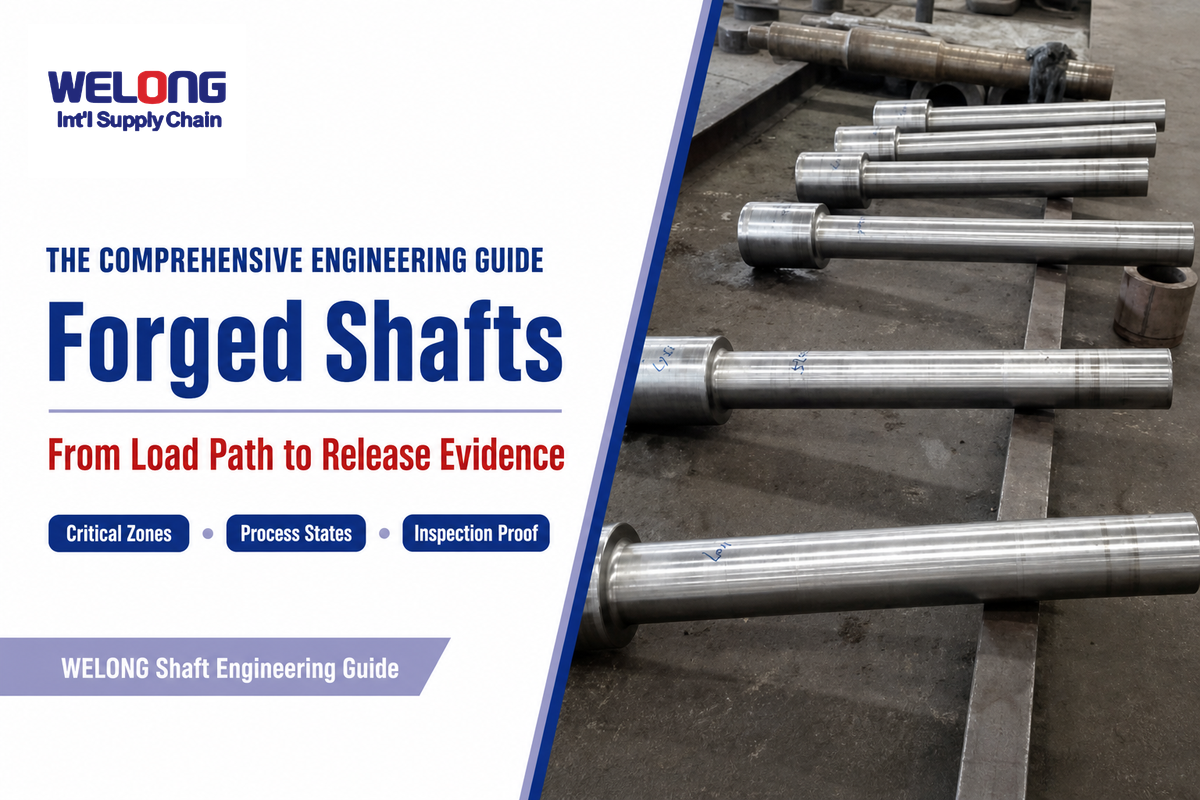
Forged shafts are worked metal components built to carry rotation, torque, bending, axial force, or a combination of these loads. What matters to engineering is not simply whether a shaft was forged. It is whether the material, deformation route, geometry, heat treatment, machining sequence, inspection access, and release evidence all fit the duty.
This guide follows that question from service load to released part. It is intentionally different from China Welong’s forged shafts solution page, which covers commercial capabilities and drawing-specific sourcing. Here, the focus stays on engineering decisions, inspection timing, and how to read evidence without turning a process label into a performance guarantee.
The short version
- Begin with the shaft’s load zones and geometry transitions, then decide what forging route and material state can support them.
- Translate the finished drawing into intermediate states that preserve machining stock, datums, test access, and traceability.
- Treat test method, test timing, coverage, and acceptance criteria as four separate decisions.
- Release evidence should connect the applicable specification and edition to the exact part, process state, and disposition.
What a Forged Shaft Is—and What the Label Does Not Prove
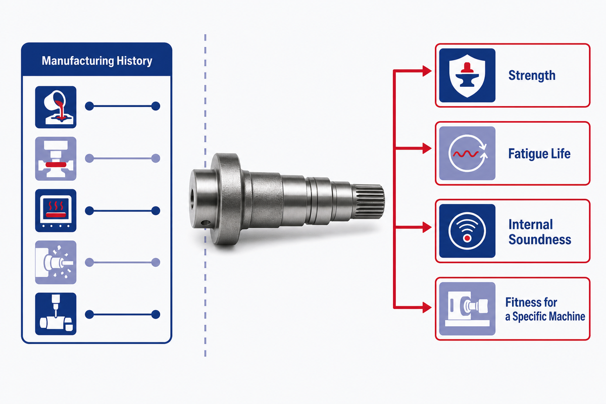
A forged shaft is a shaft-shaped component produced by plastically deforming solid metal under compressive force. Possible routes use open dies, impression dies, upsetting, drawing, or a combination of operations. “Forged,” however, describes a manufacturing history. It does not, by itself, prove strength, fatigue life, internal soundness, corrosion resistance, or fitness for a specific machine.
This distinction is straightforward: forging changes both shape and microstructure, but the result depends on how the change was made. The Forging Industry Association’s design guide connects material choice, product geometry, grain flow, and heat treatment rather than presenting any one variable as sufficient. NIST materials-reliability work likewise treats flow stress and recrystallized grain size as functions of hot-working conditions, not as automatic properties of the word “forged.”
This distinction matters when comparing a forged steel shaft with a part machined from wrought bar or produced by another route. Machining is a shape-removal step, not a material origin. Machined shafts may begin as rolled bar, a forging, or another wrought form. Fair comparison therefore holds alloy, heat treatment, surface condition, geometry, and loading constant before attributing a difference to the upstream route.
Evidence boundary: “Forged” belongs in the route description. Performance belongs in requirements and results tied to the actual part.
Start With the Load Path, Not the Forging Process
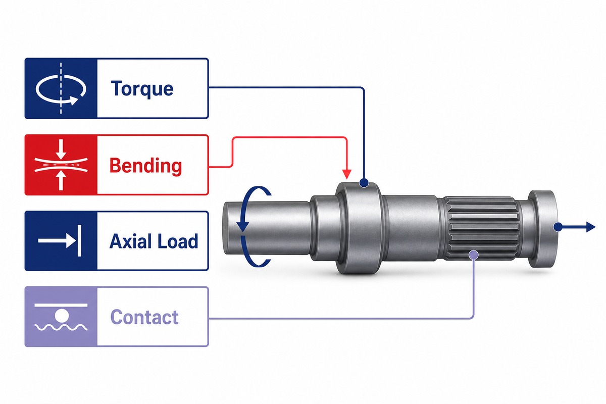
Load-path review tells an engineer where the shaft needs resistance, stiffness, surface integrity, and dimensional control. One zone may carry torque, another bending, and a thrust face axial force, while a bearing seat or spline transfers contact stress. Treating the whole part as one uniformly loaded cylinder hides the transitions where local demand is highest.
Below, the Shaft Load-to-Zone Map serves as a first-pass thinking tool. It does not calculate stress or replace fatigue analysis. Its purpose is to connect each service action with the feature, likely damage mode, and evidence that should receive attention.
| Service action | Critical zones | What can concentrate demand | Evidence question |
|---|---|---|---|
| Torque | Smallest effective diameter, spline roots, keyways | Notches, abrupt section loss, contact damage | Are shear-critical transitions represented in the analysis and surface inspection? |
| Bending | Shoulders, overhung ends, bearing-span changes | Fillet radius, misalignment, runout, load reversal | Which surface sees alternating tensile stress, and how is that surface finished? |
| Axial load | Thrust faces, retaining grooves, threaded ends | Face squareness, thread roots, preload variation | Which datum controls the loaded face and its relationship to the axis? |
| Contact | Bearing journals, gear seats, splines, seal tracks | Fit, hardness profile, finish, edge loading | Does the released state match the specified surface and dimensional condition? |
Loads do not act separately in real equipment. Torque and bending commonly overlap, and a press fit or thermal gradient can add a local stress state. Manufacturing can also leave residual stress that interacts with service loading. Starting with the load path does not ignore those effects; it identifies the zones where material direction, heat treatment, machining, surface condition, and inspection evidence must later be reconciled.
Direction matters. A NIST-indexed study of forging steels and crankshaft fatigue work published through J-STAGE show why test context and material direction cannot be reduced to a process label. That crankshaft study found direction-dependent fatigue behavior relative to forged grain flow in its tested steels. It does not supply a design value for another shaft. “Grain flow follows the axis” is therefore not enough: the relevant question is how local flow, inclusions, geometry, and maximum stress direction meet at the critical zone.
Geometry Transitions Turn Global Loads Into Local Problems
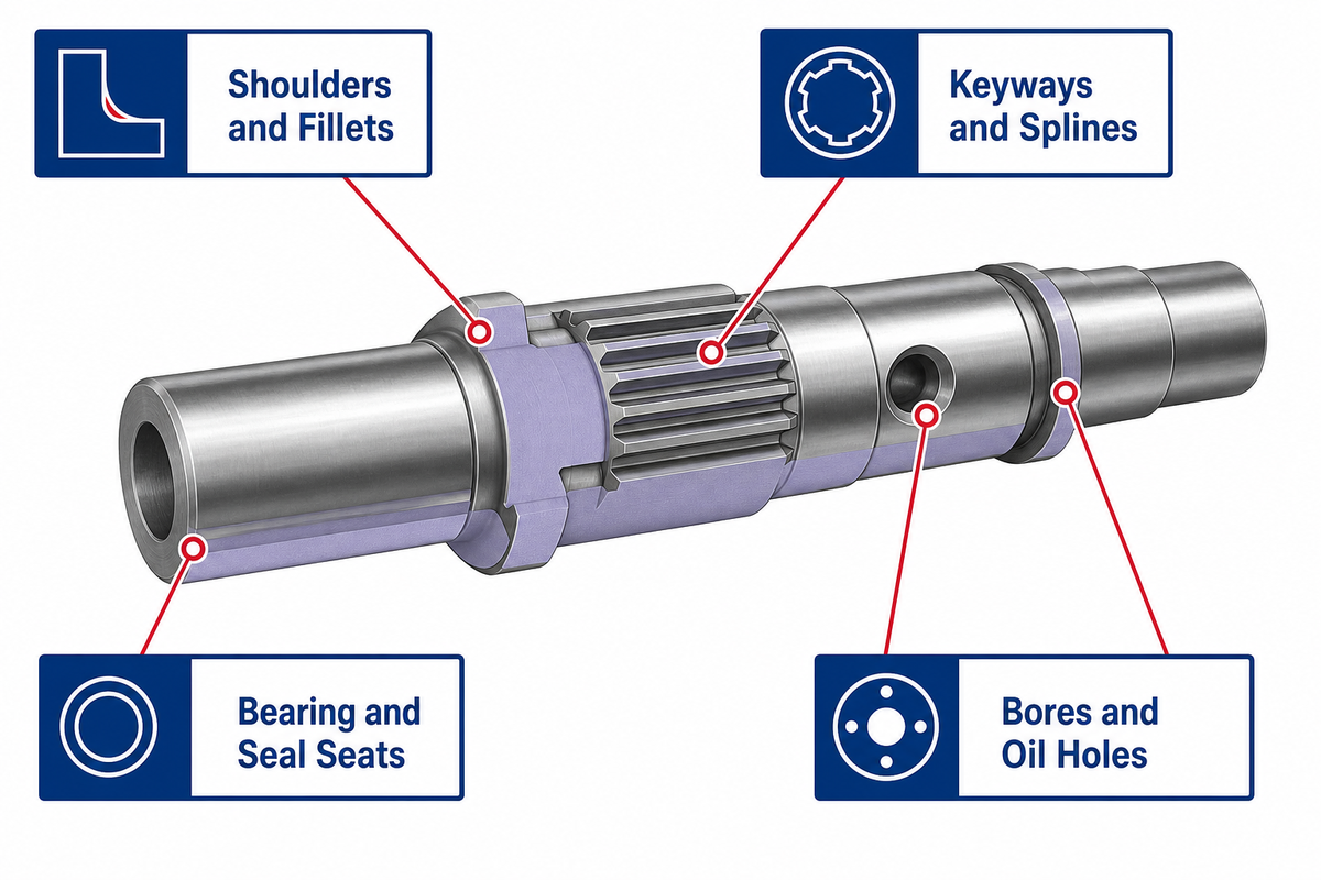
Shaft failures and inspection disputes often become local at shoulders, fillets, keyways, spline roots, cross-holes, bores, and fitted surfaces. These features interrupt the nominal section or change how force enters the shaft. Even an acceptable alloy and heat-treatment result can coexist with locally poor geometry or surface condition.
Design review should trace each transition through three views. First is the functional view: what load or fit passes through the feature? Second is the manufacturing view: how will the metal flow, where will scale or stock remain, and which surfaces will be cut? Third is the verification view: when can the zone be examined, and what geometry will the probe, yoke, indicator, or dimensional fixture actually see?
- Shoulders and fillets: confirm the radius, adjacent finish, undercut logic, and datum axis as a connected condition rather than four isolated callouts.
- Keyways and splines: review root geometry, load sharing, machining marks, case or surface treatment, and the inspection stage after those features exist.
- Bores and oil holes: separate the material volume that can be examined before drilling from the new surfaces and intersections created afterward.
- Bearing and seal seats: connect size, form, runout, finish, hardness condition, and support during measurement.
Product scope determines the right sequence. A turbine shaft, reduction-gear shaft, crankshaft, marine shaft, and general machinery shaft may share geometric language while falling under different specifications and service assumptions. ASTM A291/A291M-26, for example, has a defined scope for reduction-gear pinions, gears, and shafts rather than every shaft geometry. Here, the goal is not to create a universal detail library. It is to stop a critical transition from falling between design, forging, machining, and inspection ownership.
Shaft Form, Material, and Service Are Engineering Filters
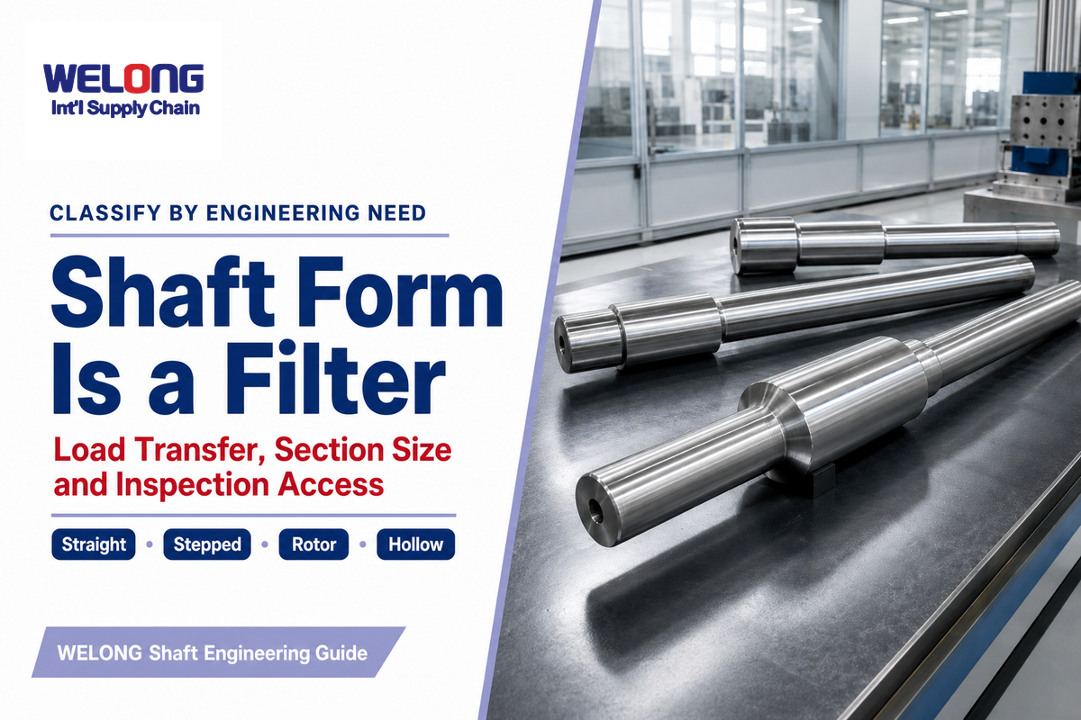
Useful classification begins with load transfer and inspection access, not a sales label. Step shafts, forged step shafts, eccentric shafts, forged crankshafts, rotor shafts, a spindle, and a shaft with a hub can all be described as forged products, yet each configuration creates a different relationship among the load path, grain structure, machining access, and datum scheme. Used this way, the table becomes a routing aid: it identifies the next engineering question, not a claim that one form is automatically better.
| Shaft type or category | Typical engineering concern | Question to resolve |
|---|---|---|
| Straight transmission steel shaft | Combined rotational torque, bending, and journal alignment | Which diameter and datum control the high-load span? |
| Step shaft or forged step shaft | Section changes, fillet stress, and dimensional accuracy | Can stock removal preserve transition geometry and concentric features? |
| Eccentric shaft or crankshaft | Eccentric configurations, cyclic bending, and directional grain flow | How are offset throws located, supported, and examined? |
| Rotor or turbine shaft | Large controlling section, balance, internal defects, and fatigue resistance | Which product standard and stability evidence govern release? |
| Spindle or precision-machinery shaft | Runout, surface finish, wear resistance, and thermal movement | At what state can the required dimensional relationship be measured? |
| Hollow or bored shaft | Wall distribution, internal voids, bore intersections, and scan coverage | What must be examined before and after the bore exists? |
| Flanged shaft or shaft with a hub | Upset material flow, face transition, and joint load transfer | How does the flange or hub connect to the critical section? |
| Polygonal, rectangle, or other custom shapes | Corner fill, orientation, machining stock, and custom datum planning | Does the variety of shapes require a shape-specific forging and inspection route? |
| Chemical-processing shaft | Corrosion, sealing surfaces, alloy compatibility, and stainless steel condition | Are environment, heat treatment, and surface requirements defined together? |
| Automotive or other high-volume shaft | Repeatability, tooling control, feature-specific fatigue, and traceability | Which controls remain valid from approval through the production volume? |
Material names also need context. Carbon steel, alloy steel, and stainless steel describe broad families, not equivalent solutions. Material selection must account for section response, corrosion environment, required mechanical properties, heat-treatment capability, and the locations where strength and fatigue resistance are needed. Hot deformation under compressive forces—whether delivered by a press, hammer, or combined manufacturing process—can consolidate material and redirect flow, but it does not erase every void or guarantee structural integrity.
Likewise, the advantages of forged material should be written as conditional engineering opportunities. A suitable route may optimize stock distribution, enhance strength in a relevant direction, or improve resistance to fatigue when alloy, temperature, reduction, heat treatment, geometry, and surface condition all support the result. Terms such as “precision-forged,” “high-strength,” “high-quality,” “superior strength,” “dependable,” or “strength and reliability” are not evidence by themselves.
This guide is not a supplier comparison. Exact specifications, custom forged steel options, custom forged parts, shaft forging capabilities, industrial applications, available machinery, high-volume capacity, and lead times belong in a drawing-specific commercial review. Keeping those decisions on the forged shaft solution page lets this article remain an engineering reference for multiple sectors, from automotive and aerospace equipment to general industrial equipment.
From a Finished Drawing to a Forgable, Inspectable Envelope
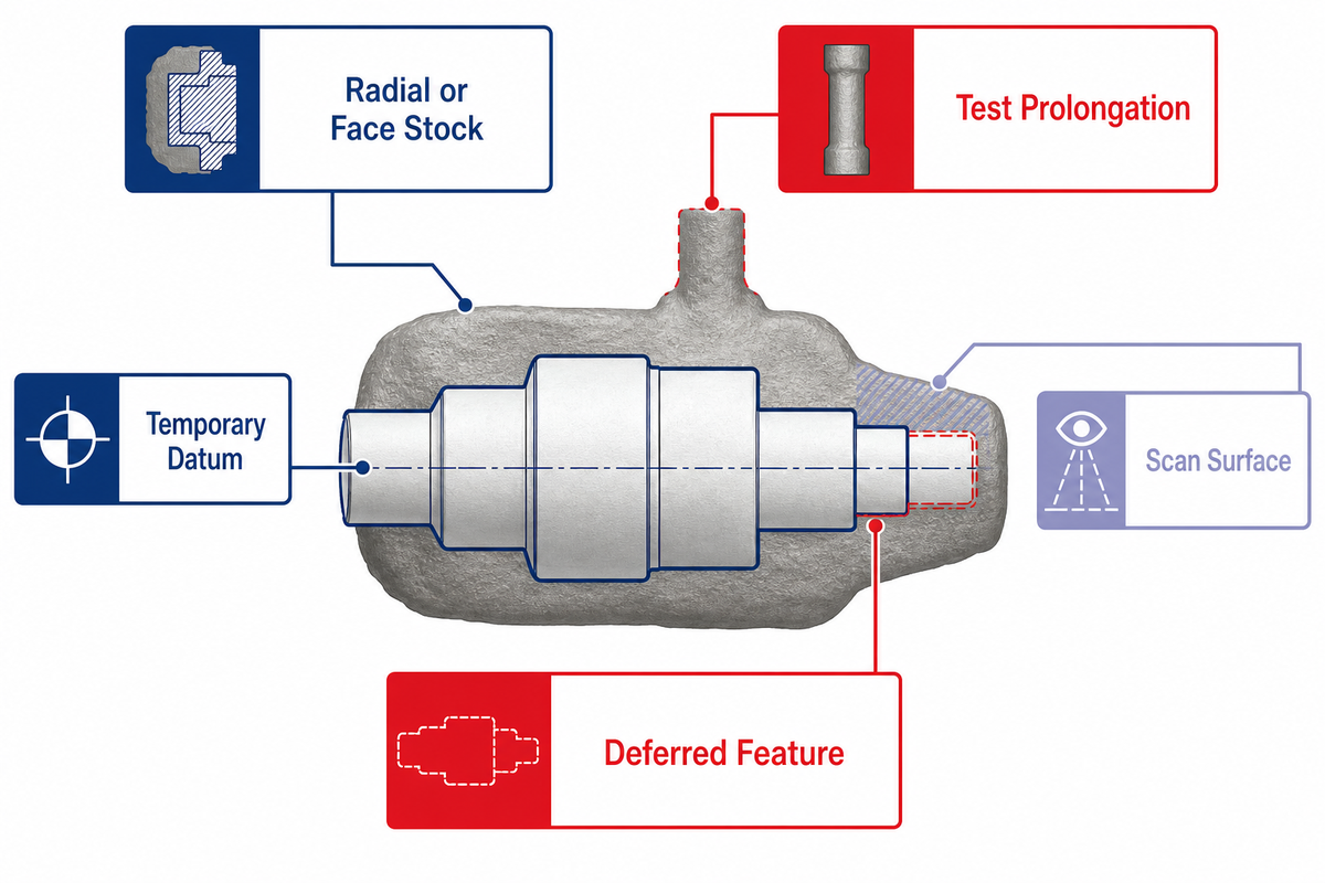
Finished shaft drawings state the released geometry, but production also needs a controlled definition of what exists before final machining. That intermediate definition may address machining stock, sacrificial extensions, test prolongations, temporary datums, bore condition, straightness allowance, heat-treatment support, and surfaces needed for ultrasonic or dimensional access.
This is a shaft-specific envelope, not a standard stock allowance. No single radial or axial value works across material, diameter, length, forging route, heat treatment, machine setup, and distortion risk. What matters is who defines each allowance, why it exists, and at which operation it may be removed.
| Envelope element | Why it may exist | Question before release to production |
|---|---|---|
| Radial or face stock | Remove scale, decarburization, distortion, or process variation | Is the allowance per side, on diameter, or total, and which final feature needs it? |
| Test prolongation | Provide representative mechanical-test material | Which section and heat-treatment condition does the specimen represent? |
| Temporary datum or center | Locate rough machining and preserve a stable axis | How is it related to functional journals after material removal? |
| Scan surface | Permit coupling, probe travel, and interpretable sound paths | What surface condition and geometry does the examination procedure require? |
| Deferred feature | Preserve examination access or avoid intersecting a zone too early | What evidence is collected before and after the feature is machined? |
ASTM A388/A388M-26 illustrates the access issue: the practice describes ultrasonic examination of steel forgings and identifies surface conditions for radial and axial examination. ASTM A503/A503M-25 provides a narrower product example for forged crankshafts, including examination zones and timing after quality heat treatment but before selected features such as oil holes. The lesson is not that every shaft should copy A503. It is that inspection state is part of the applicable product plan.
Alloy, Heat Treatment, and Controlling Section Must Agree
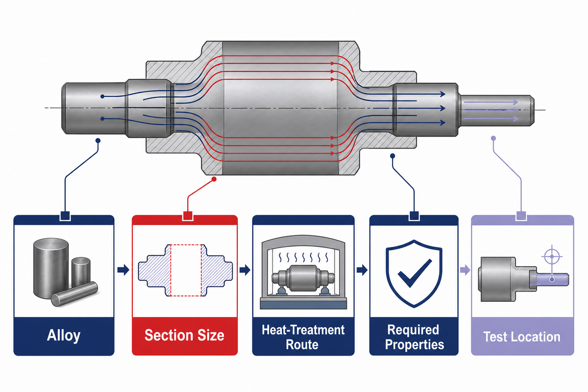
Material selection for a forged shaft is incomplete until alloy, section size, heat-treatment route, required properties, and test location are connected. A grade designation describes chemistry within a specification context; it does not guarantee the same cooling response or properties at every depth and diameter.
Large section changes make that connection visible. Controlling sections may heat and cool differently from smaller journals. A test coupon or prolongation is useful only when its location and thermal history represent the requirement it is meant to qualify. If a specimen comes from a convenient end while the critical service zone lies in a much thicker section, specification and purchase documents must explain the representation rather than leave it implicit.
ASTM A668/A668M-23 is one example of a general-industrial forging specification that distinguishes carbon- and alloy-steel classes, their required heat treatments, mechanical properties, and controlling-section/test-location logic. ASTM A291/A291M-26 is a product-specific example for carbon and alloy steel forgings used in reduction-gear pinions, gears, and shafts. Neither should be applied simply because the component is long and round; the actual product scope and order must match.
Residual stress also belongs in the process-state discussion. Forging, cooling, quenching, tempering, straightening, rough machining, final machining, and surface treatment can redistribute stress and movement. That does not make “residual stress” a universal rejection reason. It means distortion or cracking should be investigated against the sequence instead of being assigned to the last operation by default.
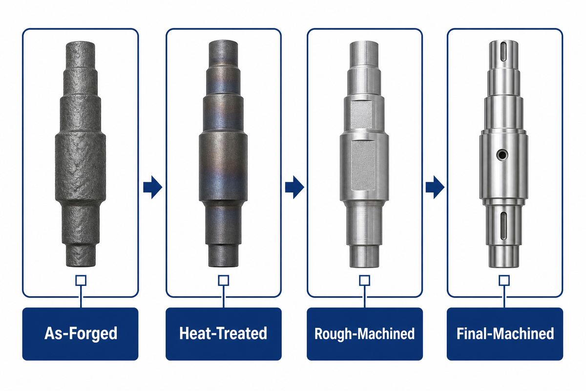
The Four-State Shaft Transformation Map
One shaft can reveal different evidence in four common states: as-forged, heat-treated, rough-machined, and final-machined. This Four-State Shaft Transformation Map prevents a report from being read without knowing which state it describes.
| State | What is established | What may still change | Useful evidence |
|---|---|---|---|
| 1. As-forged | Gross shape, deformation route, heat identity | Microstructure, hardness, straightness, surface and final dimensions | Route record, dimensions for next operation, identity marks, visual condition |
| 2. Heat-treated | Specified thermal cycle has been applied | Scale removal, rough and final geometry, local surface condition | Cycle record, mechanical tests, hardness results, applicable NDT |
| 3. Rough-machined | Usable scan surfaces and an initial datum strategy may exist | Final fits, keyways, splines, holes, finish, local treatment | UT coverage map, remaining-stock record, interim straightness or runout |
| 4. Final-machined | Functional geometry and surface features exist | Only approved finishing, preservation, marking, or rework | Dimensional report, surface examination, final identity and release disposition |
These are planning states, not four mandatory inspections. A simple shaft may combine steps; a critical product may add more hold points. Their value lies in the explicit handoff. For example, an ultrasonic report produced under a practice such as ASTM A388/A388M-26 should identify the examined state and coverage; it should not be described as a final surface examination, while a final magnetic-particle examination cannot prove the internal volume was adequately scanned earlier.
State labels also prevent a common document error: comparing results generated on different geometries as though they were the same measurement. Runout on a rough datum, hardness on an oxidized surface, and UT from a finished journal each answer different questions. Each report must identify the state and locator.
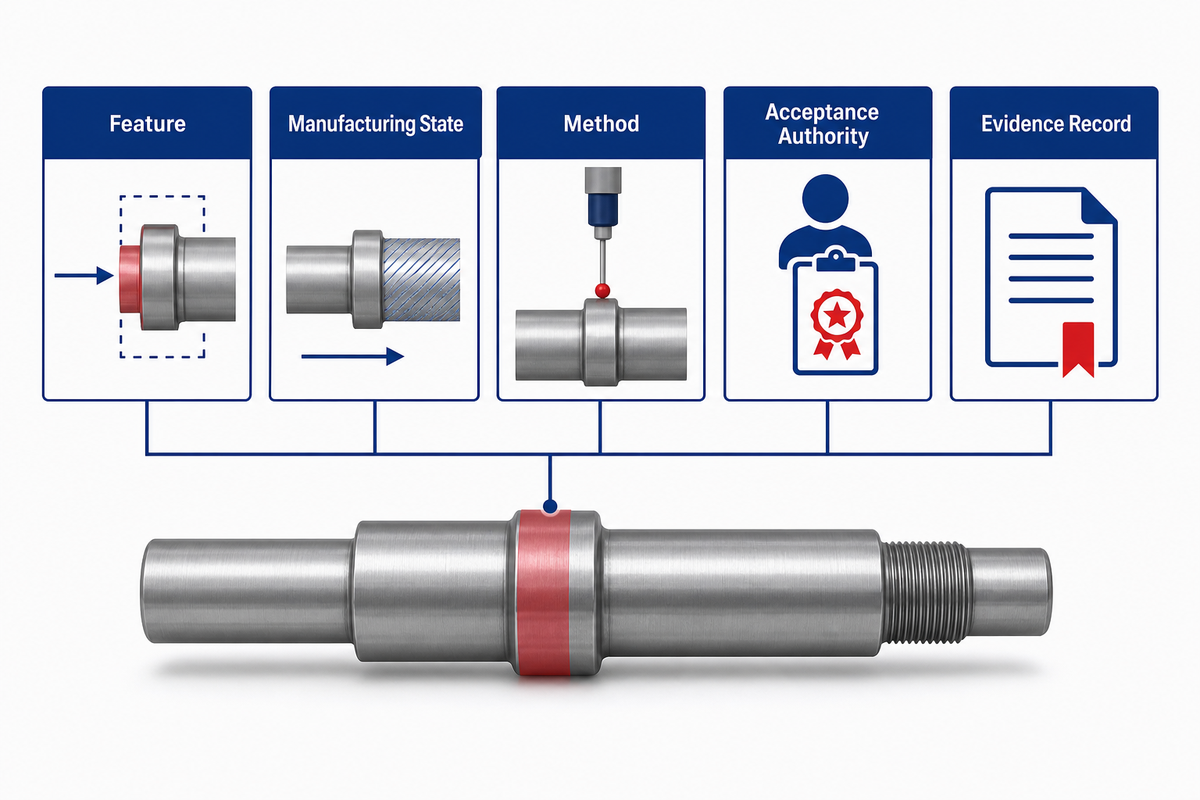
The Geometry–Process–Inspection Hold-Point Grid
An inspection plan becomes useful when it names the feature, manufacturing state, method, coverage, acceptance authority, and evidence record. This Geometry–Process–Inspection Hold-Point Grid keeps those fields together so “UT completed” or “MPI passed” cannot stand alone as an unexplained release statement.
| Feature or volume | Best decision state | Method question | Acceptance source |
|---|---|---|---|
| Core and central volume | After specified heat treatment and with adequate scan surfaces | Which directions, zones, sensitivity, calibration, and coverage apply? | Product specification, drawing, purchase order, and agreed procedure |
| Shoulders and fillets | After the relevant contour and finish exist | Can the selected surface method cover the complete transition? | Applicable material/product standard plus drawing criteria |
| Keyways, splines, holes | After machining or local treatment, as required | Which new roots, edges, and intersections require examination? | Drawing, product standard, approved inspection plan |
| Journals and fits | Final dimensional condition | Which datum axis, support method, temperature, and instrument apply? | Released drawing and dimensional inspection plan |
Separating method from acceptance is critical. ASTM A275/A275M-23 covers magnetic-particle examination procedures for steel forgings and explains its use for surface and near-surface discontinuities, but it does not contain acceptance standards or recommended quality levels. ASTM A388/A388M-26 covers ultrasonic examination, while the applicable quality level is specified in the order.
Method names answer “how was the part examined?” They do not, by themselves, answer “what was covered?”, “what indication was found?”, or “who defined acceptability?” Those answers may come from a product specification, drawing, purchaser requirement, or an agreed procedure. If one is missing, a pass stamp can create more confidence than the evidence supports.
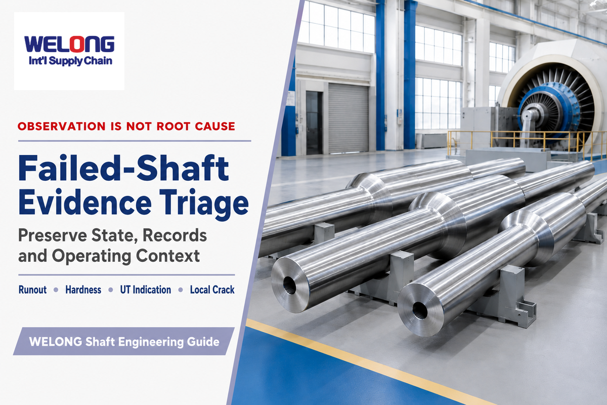
Failed-Shaft Evidence Triage
A failed measurement or damaged feature is a starting observation, not a unique root cause. This Failed-Shaft Evidence Triage routes four common symptoms toward the records and examinations needed to separate plausible contributors. It does not assign liability or replace a formal failure analysis.
| Observed symptom | Do not conclude yet | Retrieve first | Next discriminating check |
|---|---|---|---|
| Runout exceeds the drawing | “The forging was bent” | State-by-state straightness/runout, datum setup, heat-treatment and machining sequence | Repeat measurement from the specified datum and support condition; compare material-removal history |
| Hardness varies | “The alloy is wrong” | Heat identity, cycle chart, section map, surface preparation and test locations | Verify method, surface, spacing, section depth and mechanical-test relationship |
| Centerline UT indication | “It is definitely a burst” | Scan directions, calibration, indication coordinates, stock route and deformation history | Confirm repeatability and orientation; evaluate under the specified acceptance authority |
| Crack at a keyway or fillet | “Forging quality caused it” | Load history, fracture location, geometry, finish, treatment, fit, alignment and earlier NDT | Preserve the fracture and system evidence; determine initiation mode before assigning process cause |
Evidence order matters. Cleaning, grinding, cutting, or destructive sectioning can remove features needed to understand initiation. Preserve the part condition, orientation, operating context, photographs, and identifiers before rework. Then connect the observation to the exact manufacturing state and document set.
FIA’s 2024 central-burst research and published crankshaft fatigue work both reinforce the need for context. Indication location, orientation, inclusions, deformation history, stress direction, and test configuration can all affect interpretation. ASTM A388/A388M-26 also makes clear through its scope that examination technique and purchaser-specified quality levels are separate inputs. None makes every centerline indication or keyway crack equivalent. Triage narrows questions; disposition still follows the applicable engineering and contractual authority.
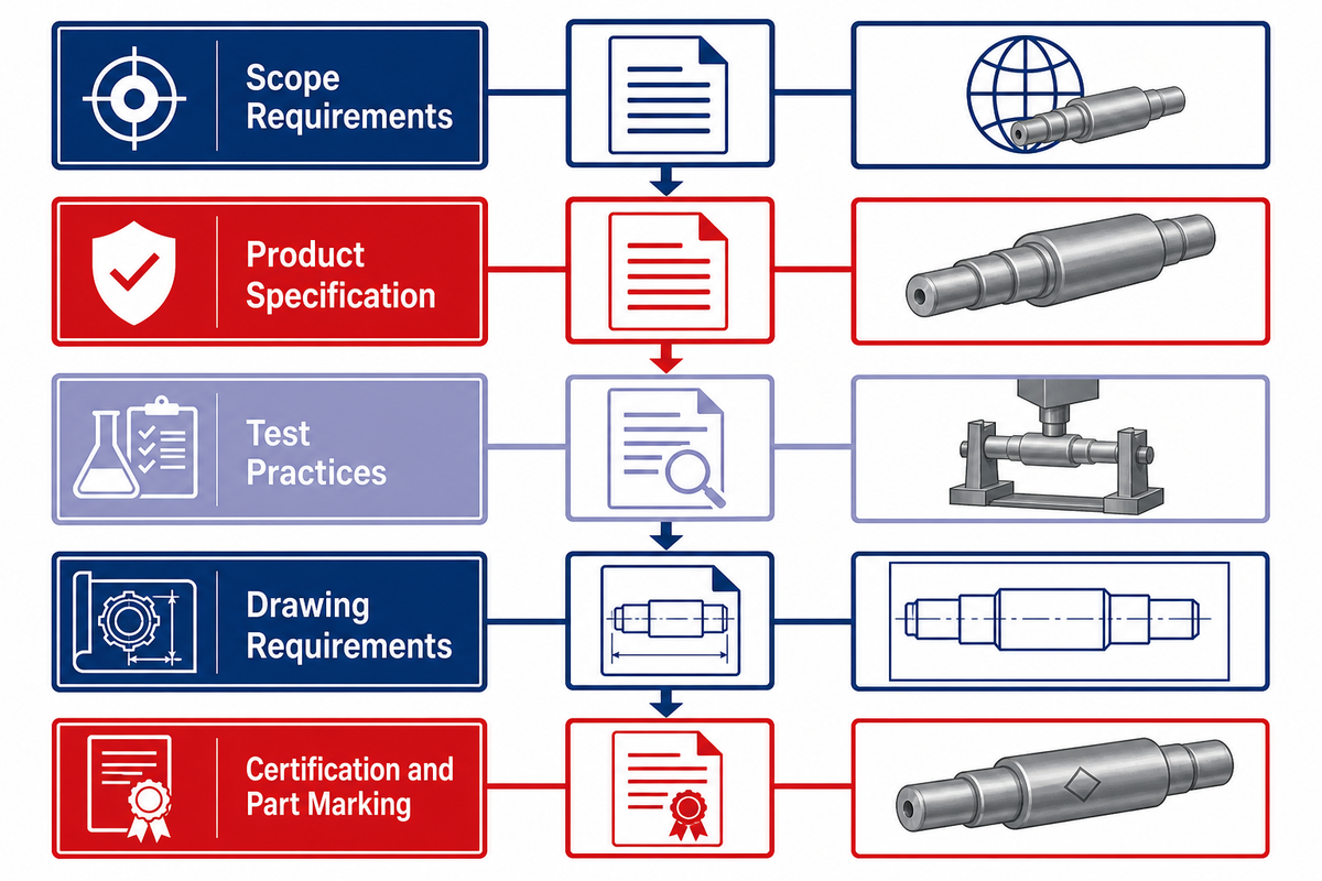
Use Product-Specific Standards Before Generic Test Methods
Identify the applicable product or application specification before converting a generic examination practice into a release requirement. “Test to ASTM” is incomplete because ASTM contains both general requirements and highly specific product and examination documents.
ASTM A788/A788M-26a covers common requirements for a group of steel-forging specifications. Its public scope states that the individual product specification prevails when requirements conflict, and additional purchaser requirements must be included in the order by agreement. This hierarchy is a practical reading rule:
- Identify the product, application, material, and destination requirements.
- Name the applicable product specification, grade/class/type, units, and edition.
- Add referenced test practices and define coverage, state, and acceptance level.
- State drawing-specific requirements, supplementary requirements, and agreed deviations.
- Make the certification and part marking reflect what was actually completed.
Examples show why scope comes first. A291/A291M addresses forgings for reduction-gear pinions, gears, and shafts. A470/A470M-05(2025) addresses vacuum-treated carbon and alloy steel forgings for turbine rotors and shafts, with its own processing, testing, NDT, and stability requirements. A503/A503M addresses ultrasonic examination of forged crankshafts. A general machinery shaft may belong somewhere else entirely.
Do not turn this list into automatic applicability. Drawing, service, jurisdiction, purchaser specification, and contract determine the controlling route. Record that decision before production starts rather than reconstructing it after an indication is found.
2025–2026 Signals: Edition Control and Linked Traceability
Two current signals matter for shaft documentation: relevant standards continue to receive new editions or reapprovals, and manufacturing traceability is moving toward linked records with clearer provenance. Neither signal creates a universal new shaft mandate.
Official ASTM pages checked for this guide show 2025 or 2026 activity for several relevant documents, including A291/A291M-26, A388/A388M-26, A503/A503M-25, A470/A470M-05(2025), and A788/A788M-26a. Operationally, the takeaway is edition control. A certificate, inspection plan, or purchase order should name the edition actually required. A webpage displaying a newer edition does not silently rewrite an existing contract.
NIST IR 8536’s 2025 second public draft describes a technology-neutral manufacturing supply-chain traceability meta-framework. It emphasizes structured recording, linking, retrieval, provenance, integrity, trusted repositories, and controlled disclosure. That is useful direction for how a future evidence package might be connected, but it is a cybersecurity supply-chain draft—not a forged-shaft inspection standard and not proof that any supplier has adopted it.
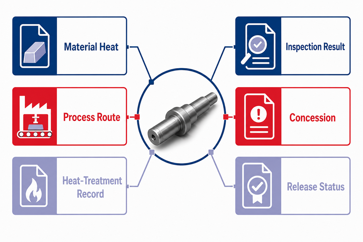
For a forged shaft, the near-term practical version is modest: use stable identifiers so the material heat, process route, heat-treatment record, inspection result, concession, and release status can be linked without ambiguity. Digital systems help, but the data definitions and ownership still have to be correct.
Release the Shaft as an Evidence Chain
A reliable forged shaft is not released by a label, one certificate, or one “passed” test. It is released when the duty, critical geometry, material and section, process state, inspection access, acceptance authority, and final records agree.
Use the four maps in this guide to structure the engineering conversation: locate the load zones, define the intermediate envelope, assign state-specific hold points, and treat a failed observation as a triage input rather than a ready-made cause. When the work moves from education to a drawing-specific sourcing decision, review China Welong’s forged shaft manufacturing options and the company’s supply-chain approach.
Discuss a drawing-specific shaft requirement
Frequently Asked Questions
Are forged shafts always stronger than machined shafts?
No. “Forged” describes upstream forming, while “machined” describes material removal; either can appear in the same part route. Compare alloy, heat treatment, geometry, surface condition, loading, and part-specific evidence before claiming one is stronger. The question is route-specific, not label-specific.
When should ultrasonic testing be performed on a forged shaft?
Timing comes from the applicable product specification, drawing, purchase order, and approved procedure. For the result to be interpretable, the shaft must also be in a material and surface condition that makes the intended volume accessible. Product-specific examples must not be generalized to every shaft.
What is the difference between an NDT method and an acceptance criterion?
An NDT method defines how an examination is performed: equipment, calibration, magnetization or sound path, surface condition, scanning, and reporting. Acceptance criteria define which indications are permitted, recorded, evaluated, or rejected for the applicable product. Those requirements may appear in separate documents. For example, ASTM A275/A275M describes magnetic-particle examination of steel forgings but does not contain universal acceptance levels. Disposition authority comes from the governing product specification, drawing, order, or agreement.
Why does controlling section matter in forged shaft heat treatment?
Section size affects heating, cooling, transformation, and where test material represents the part. A small journal and a large body may not experience the same thermal response even when they share a heat and nominal grade. Specifications such as ASTM A668/A668M use heat-treatment classes and controlling-section/test-location logic for this reason. Engineers should connect the critical shaft volume with the specified heat-treatment condition, coupon location, mechanical tests, and hardness map instead of assuming one convenient reading represents every depth.
What documents should identify the manufacturing state of the shaft?
Drawing and purchase specifications should define required intermediate states and hold points, while route cards, heat-treatment records, inspection reports, dimensional reports, concessions, and release documents should identify the state actually examined. A report should also include the part or lot identity, applicable procedure, locator or zone, result, acceptance source, and disposition. Exact package contents depend on the product and contract; the essential point is that a reader can connect each result to the correct shaft and stage.
References & Sources
- Forging Industry Association — Product Design Guide for Forging
- Journal of the Japan Institute of Marine Engineering — Fatigue Strength of High-Tensile Crankshaft Steels
- ASTM A668/A668M-23 — Steel Forgings for General Industrial Use
- ASTM A291/A291M-26 — Steel Forgings for Pinions, Gears, and Shafts
- ASTM A388/A388M-26 — Ultrasonic Examination of Steel Forgings
- ASTM A275/A275M-23 — Magnetic Particle Examination of Steel Forgings
- ASTM A503/A503M-25 — Ultrasonic Examination of Forged Crankshafts
- ASTM A470/A470M-05(2025) — Turbine Rotor and Shaft Forgings
- ASTM A788/A788M-26a — Steel Forgings, General Requirements
- NIST IR 8536 Second Public Draft — Supply Chain Traceability: Manufacturing Meta-Framework
![Choke & Kill Hose: [Field Guide]](https://welongoiltools.com/wp-content/uploads/2026/07/choke-kill-hose-guide-featured-1-150x150.png)