
Get in touch with Welong Company
Work Roll Guide: Function, Wear, Inspection and Maintenance

ROLLING MILL ENGINEERING GUIDE · 2026
By Cherry · Updated September 2026
A Work Roll is the roller that contacts strip, sheet or plate inside a rolling mill. Thickness reduction occurs in the loaded gap between the two rolls. The design of the rolls and their surface condition influence the roll’s capability to produce a finished shape.
That definition is sufficiently simple, but the reality of this situation is much less so. Work rolls, due to their loading condition, bend, expand asymmetrically when heated, and wear along their length. They also come in contact with backup rolls and develop a surface record of the various disruptions a processing machine experiences. Treating each repetitive mark as a “bad roll” may cause a mill to grind away good material without finding the root cause. Focusing only on the pounds of material processed can also hide a crack, pickup band, or abnormal thermal event.
Quick answer: to determine the symptoms, refer to the campaign record to evaluate the conditions under which the problem occurred, and to confirm the roll physical conditions, perform an isolated inspection of the roll. Evidence from these will determine the next course of action, which in most cases won’t be replacing the work rolls based on a universal life number.
What Is a Work Roll?
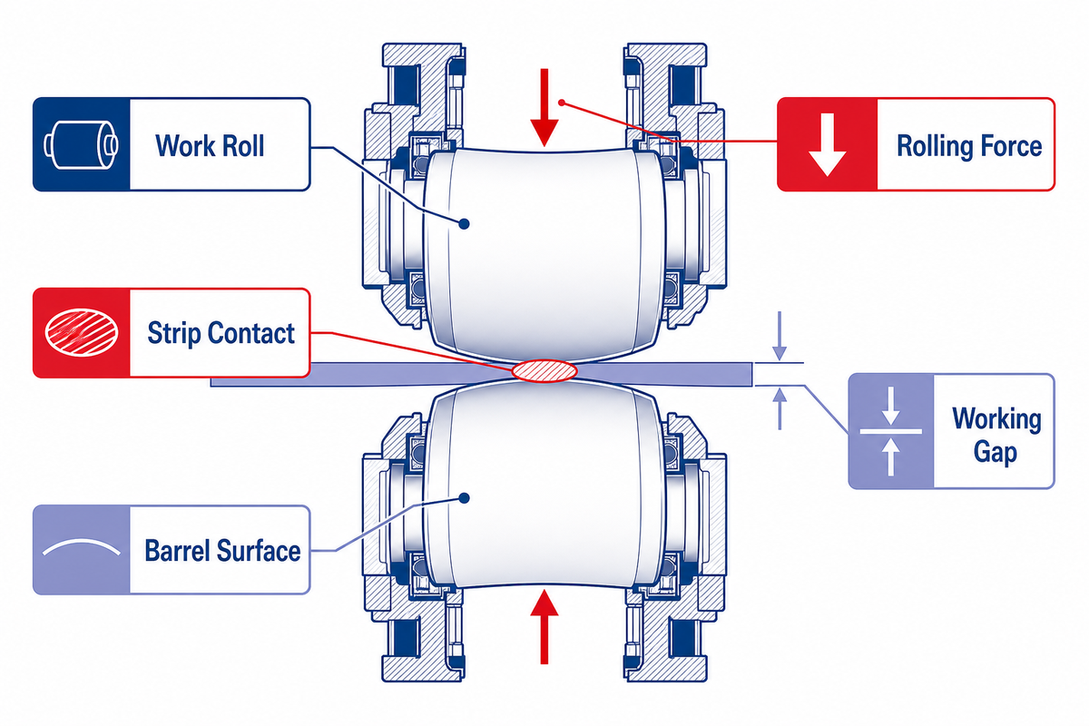
The work roll is the rolling-stand component that contacts the strip. Work rolls transmit rolling force, establish the working gap, and offer a controlled surface to the material. Since the barrel comes in contact with the product, changes in diameter, crown, roughness, or cleanliness of the barrel appear as changes in thickness, flatness, or surface quality of the product.
In a two-high stand, the same rolls contact the material and resist bending. The other arrangements (four-high and cluster) distribute these functions in a more deliberate way: smaller work rolls contact the strip, while larger backup rolls support them. The diameter of the work rolls can be small, but this can also mean that controlling bending and support contact can become a more important consideration.
“Rolls are the basic tool of rolling mills.”
This phrase shouldn’t be confused with “work role,” construction-management software, or a rolling worktable. Here, “work roll” always means a roll in metalworking. For the broader product family and adjacent components, the Welong mill rolls hub provides the commercial site context.
How Work Rolls and Backup Rolls Share the Load
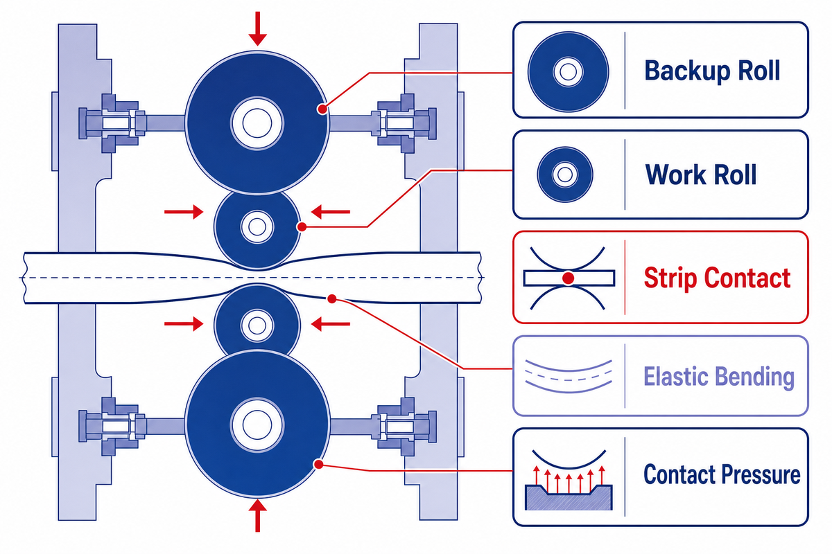
Work rolls and backup rolls aren’t equivalent components. Strip contact occurs at the work roll, while the backup roll contacts and supports the work roll. Even though a fault in either member can influence the same final strip, these rolls have distinct zones of contact, bending behavior, and surface functions.
In order to resist bending, support rolls are needed. Without support, the barrels would deflect and the loaded gap would vary across the strip width. Backup rolls diminish the bending tendency, but support isn’t perfect: the bodies of the rolls deform, bearings and chocks carry loads, and the contact pressure between the work roll and backup rolls varies across the barrel.
One strip mill roll can’t solely account for a center buckle or edge wave. The root cause could reside in mechanical crown, roll bending, backup roll profile, thermal distribution, misalignment, tension, a control response or a system reaction. The point isn’t “Which roll looks guilty?” but “Which measured pattern can reproduce the defect’s position, wavelength, and occurrence?”
| Evidence surface | Work-roll responsibility | Backup-roll or system alternative |
|---|---|---|
| Product contact | Direct transfer of roughness, pickup or local damage | Indirect influence through support and deflection |
| Bending | Smaller diameter makes loaded profile sensitive to support | Profile and chock conditions alter support distribution |
| Surface indication | Strip-side cracks, spalls, pickup and texture change | Inter-roll contact marks, bearing or alignment evidence |
A 2024 temperature and crown study considered the work and backup rolls and checked the calculations against field measurements. That paired treatment matters: the loaded stand behaves as a system, not as independent cylinders. The study is also a useful reminder to keep model inputs and stand conditions attached to every result.
Which Rolling Regime Are You Diagnosing?
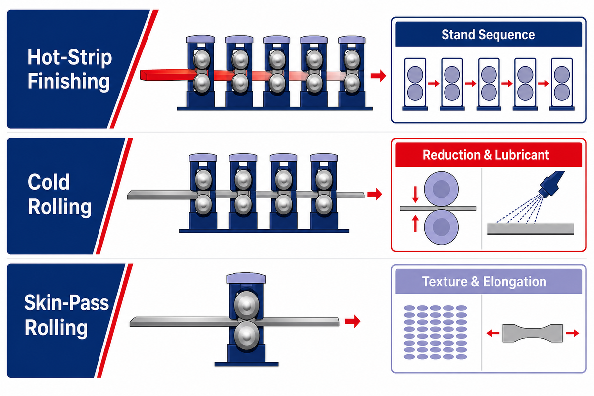
Any broad Work Roll guide needs an operating boundary before it can deal with wear. Hot-strip finishing, conventional cold rolling and skin-pass rolling all use the same component name, but they have different temperature, lubrication, surface-transfer and dominant-failure conditions. Evidence from one regime shouldn’t be carried into another without justification.
| Rolling regime | Work-roll duty that moves forward | Evidence that must stay local |
|---|---|---|
| Hot-strip finishing | Thermal cycling, oxide/scale interaction, cooling distribution, crown and wear | Stand sequence, strip temperature, coolant layout and width mix |
| Cold rolling | Surface finish, lubrication, contact fatigue, cleanliness and tight gauge/shape control | Reduction schedule, lubricant, strip strength, roughness method and cleanliness history |
| Skin-pass rolling | Deliberate texture transfer, topography retention and downstream forming behavior | Texture process, elongation, lubricant retention, sheet topography and stamping requirement |
A 2025 review of surface texturing from skin-pass rolling through sheet forming explains how a work roll transfers texture to the sheet, influencing lubricant distribution and later formability. Wear can round the roll texture and alter surface transfer. In this regime, “surface wear” isn’t just lost roll stock; it can change the controlled surface of the final formed sheet.
Crown, Elastic Deflection and Thermal Profile
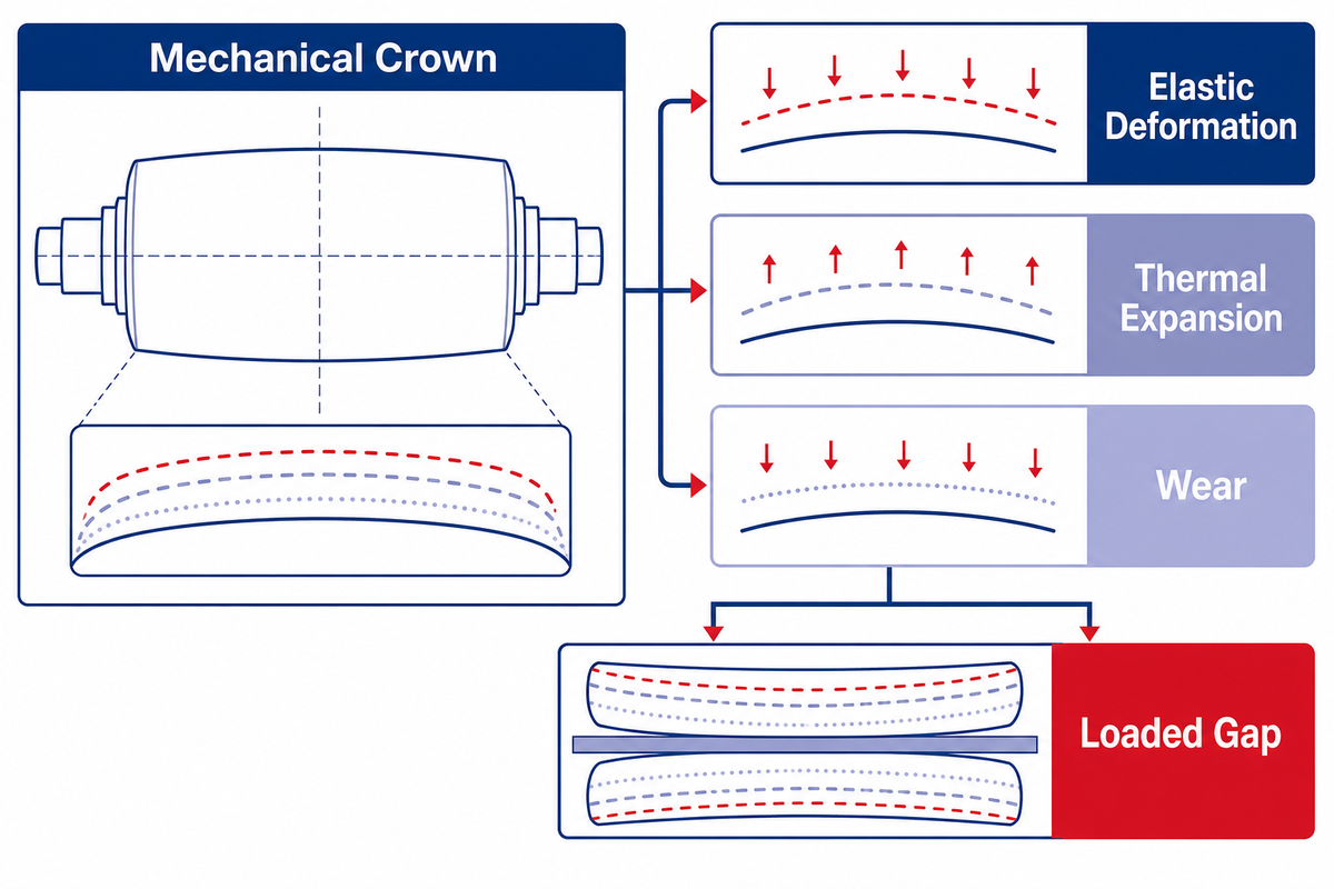
Roll crowning is the intentional or developed variation of diameter along the length of a roll barrel. The operating profile is the combination of manufactured geometry, elastic deformation, thermal expansion, wear and any active bending or shifting response. Only looking at a cold ground profile brings several of those terms into view.
Mechanical crown
Ground crown gives an unloaded roll a shaped profile. When separating force is applied, elastic bending and flattening at contact points alter that shape. The same profile may produce different loaded gaps when width, force schedule or product mix changes. This is an engineering-system difference; it isn’t grounds for a request to change a roll specification without mill calculations.
Thermal crown
The strip heats, the barrel cools, headers remove heat. Because there’s contact and cooling that vary across the face, there’s a nonuniform heating pattern. Local expansion can cause hot profile shifting due to the accumulation of coils, widths, and pauses. The 2024 study reported, for its modelled cooling case, a reduction in maximum work-roll temperature from 136 °C to 38 °C and a reduction in maximum thermal crown from 0.67 mm to 0.33 mm. These values describe the study’s conditions and don’t represent operational conditions of a new mill.
Wear profile
Material removal causes wear; thermal expansion does not. The cross-direction wear pattern follows rolled widths, local contact pressure, scale and oxide behavior, cooling, material response and campaign sequence. Thermal crown can change throughout a campaign, while wear remains until grinding. That distinction matters when temperature changes correct a shape problem but a surface mark stays fixed at one barrel position.
What Li and colleagues presented in 2024 was an integration of theoretical calculations, simulation and field measurements. The important lesson isn’t their reported cooling value. The lesson is that it’s necessary to consider like with like: cold profile versus cold profile, stable thermal state versus stable thermal state, and same coordinate system across grinding, stand, and strip records.
Work Roll Construction and Material Families
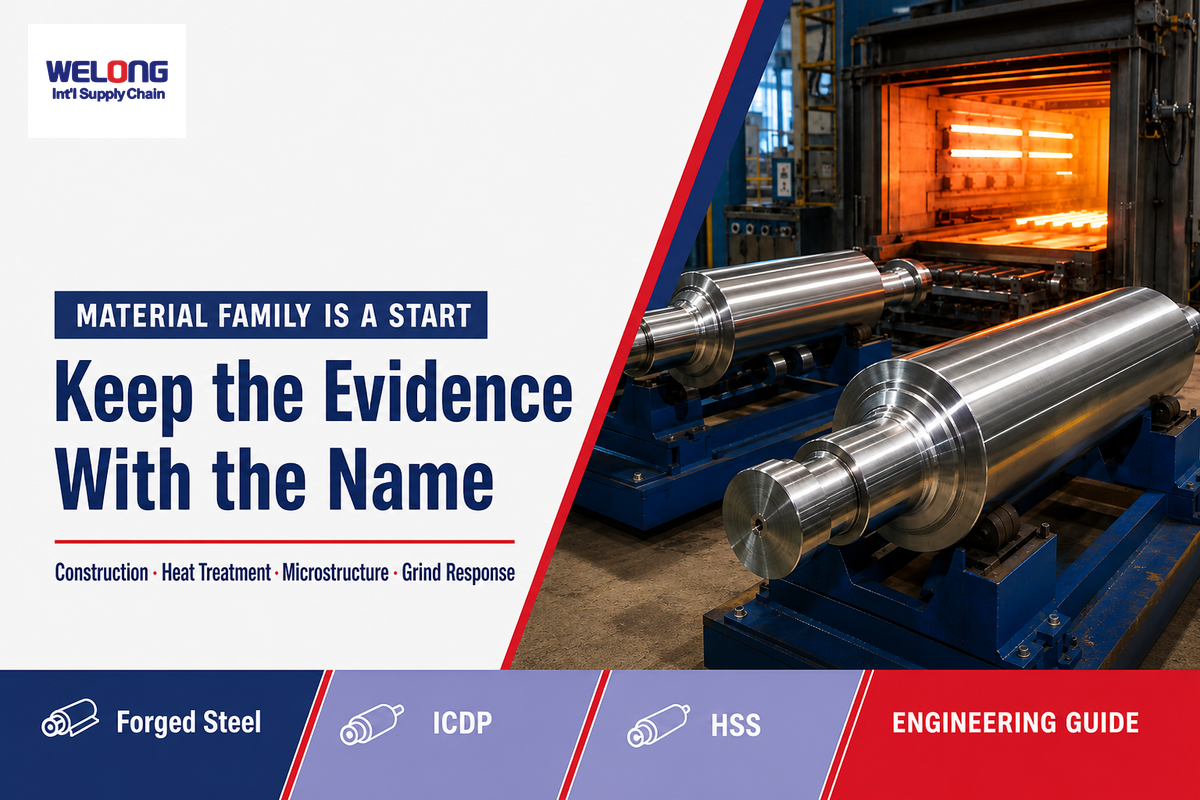
When considering work-roll materials, balance is sought among wear resistance, thermal-fatigue behavior, contact-fatigue strength, toughness, roughness retention and grindability. The balance is of varying concern for each stand and each process. Hence, a family name, while limiting the scope, isn’t the last word in the engineering conversation.
| Family or construction | Why mills use it | Evidence to keep with the name |
|---|---|---|
| Forged alloy steel | Through-section integrity and controlled hardened layer for demanding cold-rolling or support duties | Heat treatment, hardness profile, residual stress, ultrasonic result and remaining diameter |
| ICDP | A wear-resistant outer working layer with a tougher core in hot-strip finishing applications | Shell chemistry and depth, graphite/carbide structure, thermal-cycle history and stand position |
| High-chromium iron or steel | Wear and oxidation response suited to defined hot-rolling positions | Microstructure, hardness gradient, cooling practice and observed wear mechanism |
| High-speed steel (HSS) | Carbide-rich working layer and wear resistance in selected finishing stands | Mill trial scope, grind response, surface condition, campaign mix and cost per usable millimetre |
The 2021 ICDP study is valuable because it shows how much detail hides inside one family label. Its tested outer layer contained 4.5 wt.% Ni, 1.7 wt.% Cr and 0.7 wt.% Nb. The design varied a 1,250–1,255 °C liquidus range and 1.10–1.15 wt.% Si, then tested hot wear at 250 °C and 350 °C. Those numbers pertain to that manufacturing system and experiment, and should not be used as a purchase specification. See the full study and test scope.
One 2022 hot-strip-mill analysis reported 14,000–20,000 Mg of rolled material per millimetre of radial wear for HSS rolls in its studied F5/F6 stands, compared with 2,000 Mg/mm for the studied high-chromium rolls. In addition, that article suggested that about 30% of roll reconstructions were attributable to operating the rolls beyond their intended limits. These numbers support the notion that the material used and its discipline interact. They shouldn’t be viewed as a guarantee of life.
Where mill-specific grade, heat treatment, hardness profile, and respective dimensions are concerned, Welong’s mill-roll grade selection resource can be used as a starting point. Confirm the information with the mill and roll engineer. Background on the forged component process controls can be found in the forged shafts process guide (adjacent manufacturing context, not a work-roll specification).
Surface Condition: Wear, Pickup, Chatter, Cracks and Spalling
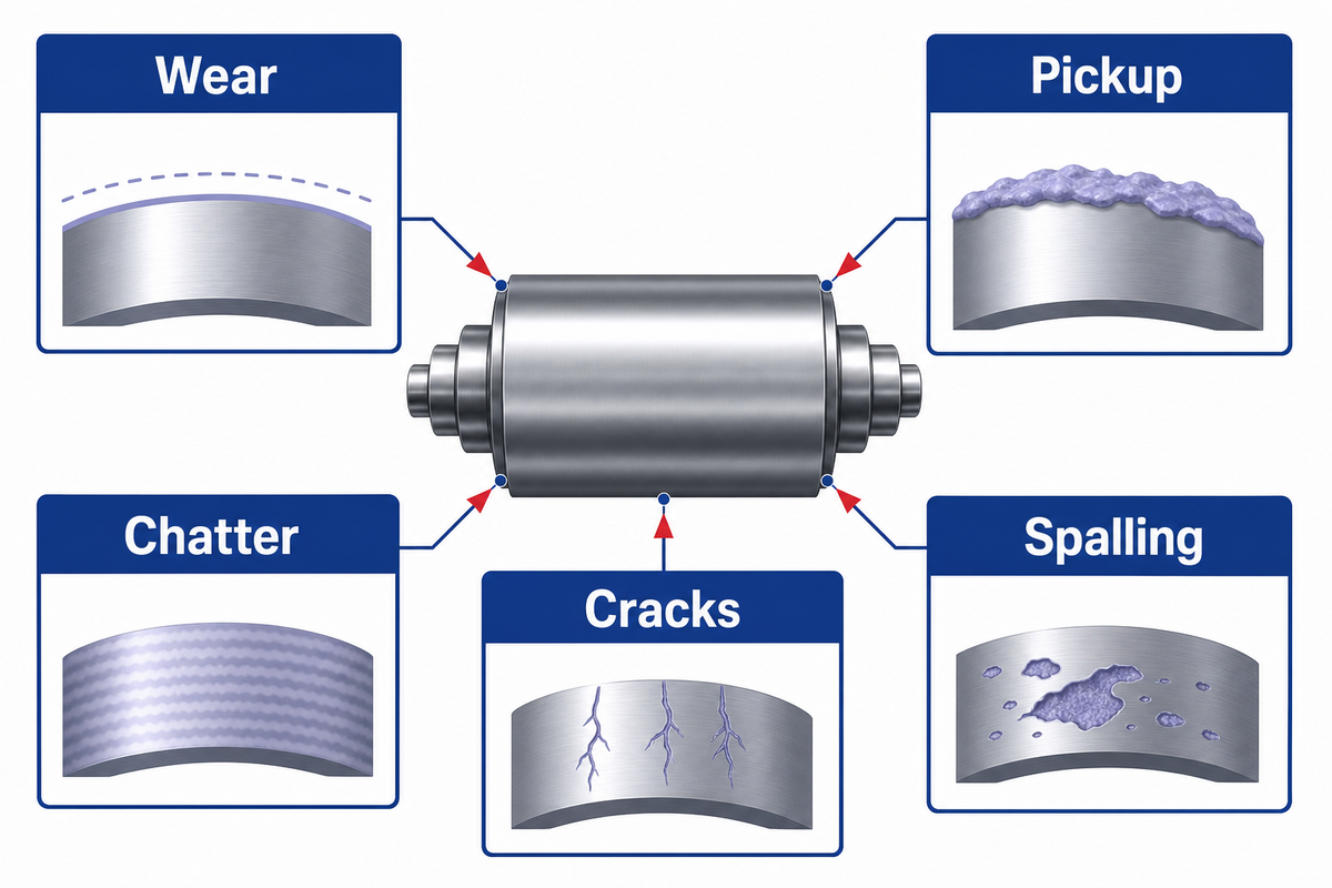
Terminology used in describing failure modes such as “roll failure” is far too vague for basic failure mode analysis. Changes in wear geometry or texture occur gradually; material pickup transfers contamination to the barrel; chatter results in a pattern; cracks and spalling indicate a local failure. Each of these defines a specific evidence path with unique, immediate failure concerns.
Wear
Smooth changes in wear can lead to edge relief, change of crown or change in surface roughness. Abnormal wear may be localized by width, stand, cooling zone or contact band. Compare profile traces in the same barrel coordinate system and record the stock removed during grinding. “The roll looked polished” isn’t a measurement.
Pickup and banding
Material that becomes adhered or transferred to the roll may build up a raised band on the strip. Position matching strip defects and barrel locations provide strong evidence for the roll-side hypothesis. Chemistry, temperature, lubrication, scale and preceding process events should be covered in the analysis since they may explain adhesion of material.
Chatter
Chatter isn’t the only possible explanation for vibration and the development of a periodic line. Matching pitch may connect the mark with roll rotation, but vibration from a driven bearing, stand, strip or control system can overlap. Keep time, speed and vibration data prior to removing hardware; otherwise the evidence will be lost when the campaign is complete.
Cracks and spalling
Variation in thermomechanical processes, overload, cobble damage, residual stress and discontinuity may drive thermal crack growth, while spalling removes surface material. Brittle failure and material loss increase the risk level. Follow the mill’s isolation, handling and engineering-disposition procedure instead of relying on an online photograph.
Surface appearance isn’t a marker for structural health. A 2022 ICDP case study examined an F5 top roll whose chemical composition and unaffected surface hardness met the applicable standard, yet about 30% of the surface exfoliated. Spalling was attributed to poor shell-core bonding, microcracks, and scale inclusions. There was a combination of visual and ultrasonic testing, chemistry, metallography and hardness test interventions. This case shows the harm and the important reminder to not consider acceptable surface hardness of the composite roll as an indicator of its integrity.
The peer-reviewed cold-strip work-roll failure study examined premature failures through surface and material analysis. The larger general lesson is about procedure: name the identified mechanism, provide evidence to confirm the mechanism, and ensure the proposed causal mechanism is consistent with the evidence.
Surface Symptom-to-Evidence Matrix
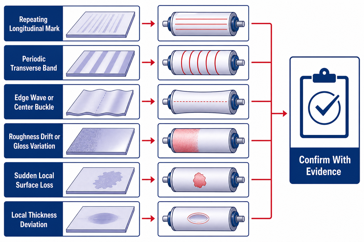
Use the Surface Symptom-to-Evidence Matrix as a screening tool. It links a product observation to a roll-side clue, possible process alternatives, and the next confirming check. It doesn’t replace the mill’s defect standard or allow inspection with the equipment energized.
| Symptom type | Roll-side clue | Do not ignore | Confirm with |
|---|---|---|---|
| Repeating longitudinal mark | Fixed barrel-position pickup, groove or crack | Guide contact, trapped debris, upstream mark | Cross-direction position match and isolated surface inspection |
| Periodic transverse band | Circumference-linked roll mark | Drive, bearing or stand vibration | Pitch-to-circumference calculation plus speed/frequency record |
| Edge wave or center buckle | Loaded-profile or wear-profile change | Tension, width schedule, roll bending, cooling and backup-roll support | Shape data, profile trace, thermal history and control record |
| Roughness drift or gloss variation | Texture wear, polishing or contamination | Strip material, lubrication, cleaning and measurement method | Mapped roughness readings under the same method |
| Sudden local surface loss | Spall or overload damage | Cobble, thermal shock, subsurface indication | Immediate controlled stop, isolation and engineering/NDT disposition |
| Local thickness deviation | Diameter loss, groove or local crown change | Gauge control, force measurement and upstream thickness | Thickness map aligned to barrel coordinate and profile trace |
| Dull or bright patch | Local polishing, roughness loss or residue | Strip chemistry, lubricant and cleaning history | Mapped roughness plus cleaned-surface observation |
| Edge build-up or edge mark | Width-dependent wear step or pickup | Width schedule, edge drop, coolant coverage and guides | Campaign width sequence and edge-zone profile |
| New mark after a cobble | Bruise, dent, overload crack or embedded debris | Damage to guides, bearings, backup roll or adjacent stand | Event-time trace and targeted isolated inspection |
The strongest early clue is a repeatable spatial or frequency match. The strongest confirmation comes after process alternatives have been checked and the isolate roll has been measured or tested. If position, pitch and inspection don’t agree, then don’t fit the evidence to a roll-failure story.
Inspection Between Campaigns
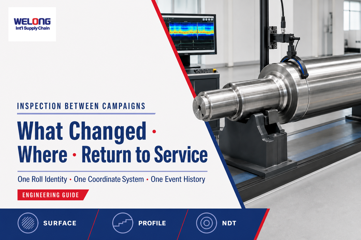
Between campaigns, inspection should answer three questions: what changed, where did it change, and does the change affect safe return to service? Clean records identify the roll, stand, top/bottom position, drive/operator side and barrel coordinate before observations are recorded. Condition monitoring can improve service-life decisions when it ties dimensional profile, surface defects, cylindrical geometry and mill-control events to the same roll record.
- For the visual surface, record the location and size of unusual pickup, heat tint, cracks, pits, spalls, bruises or bands.
- For dimensions and profile, compare diameter, crown/profile, runout and removed stock with the same datum and measurement method.
- For texture, map roughness rather than reporting a single convenient spot.
- For nondestructive testing, use the qualified method and acceptance criteria relevant to the roll design and damage mechanism. Eddy-current, ultrasonic and magnetic methods aren’t interchangeable.
- Add cobbles, cooling interruptions, overloads, vibration alarms and abnormal strip events to the same roll identity and event history.
Grinding data, production reports, roll files, statistical data, and eddy-current inspection were employed in the 2022 mill study. No single technique provided the answer. The result of this study is thus a practical model for combining evidence sources. Each result must retain the date, instrument, or source, coordinate, unit and be reviewed.
Safety boundary: observing from a protected position isn’t the same as a hands-on inspection. Further examination, cleaning, measurement, roll handling and testing must comply with the mill’s isolation, guarding, lifting instructions, OEM instructions and trained personnel instructions.
Grinding, Campaign Records and Change Criteria
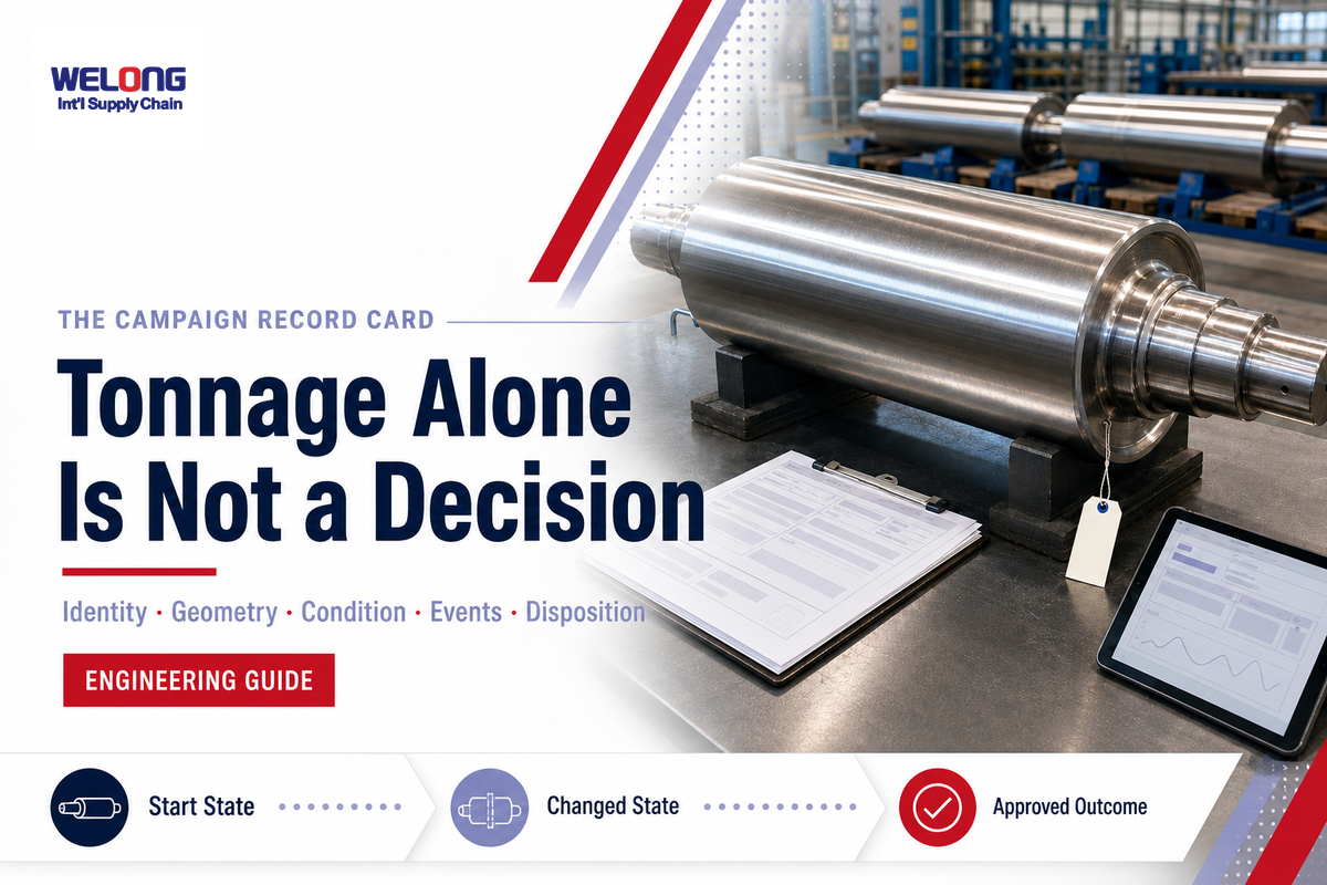
Grinding removes material to restore the required profile and surface, while replacement or condemnation decisions determine whether usable roll stock remains. Those decisions add remaining diameter, damage depth, subsurface integrity and design limits to the evidence set. Material removal may alter the residual stress near the working layer, so the post-grind inspection is evidence in itself. Grind tonnage is useful to compare runs, but doesn’t answer either decision on its own.
The Campaign Record Card
Keep one record for each roll position and campaign so measurements, events and dispositions aren’t mixed across stands. Electronic or paper records both work when the mill uses the chosen format consistently.
| Field group | Minimum record | Decision value |
|---|---|---|
| Identity | Roll ID, stand, top/bottom, drive/operator side, material family | Prevents data from different positions being mixed |
| Geometry | Start/end diameter, profile, runout, stock removed | Separates wear, thermal response and grinding history |
| Production | Tonnage or length, widths, grades, reductions, stand schedule | Makes campaign comparisons conditional rather than generic |
| Condition | Roughness map, visual findings, crack/spall indications, NDT result | Connects surface state to the chosen grind or disposition |
| Events | Cobbles, cooling loss, overload, vibration and strip-defect time | Explains outlier wear and prompts targeted inspection |
| Measurement method | Instrument, method, calibration state and measurement coordinate | Keeps profile, roughness and diameter trends comparable |
| Post-grind check | Final diameter, profile, surface result and applicable NDT result | Confirms whether the intended removal outcome was achieved |
| Disposition | Return, hold or condemn decision, approver, timestamp and next action | Closes the evidence trail for the next campaign |
Trend stock removed per campaign and rolled quantity per usable metre. Product mix and stand position must remain comparable. A falling ratio doesn’t automatically indicate poor roll material; it could reflect increased duty, changed grinding practice, measurement drift or damage. Use the mill-approved minimum diameter and damage-removal rules instead of importing a condemn diameter from another installation.
4-Step Work Roll Decision Framework
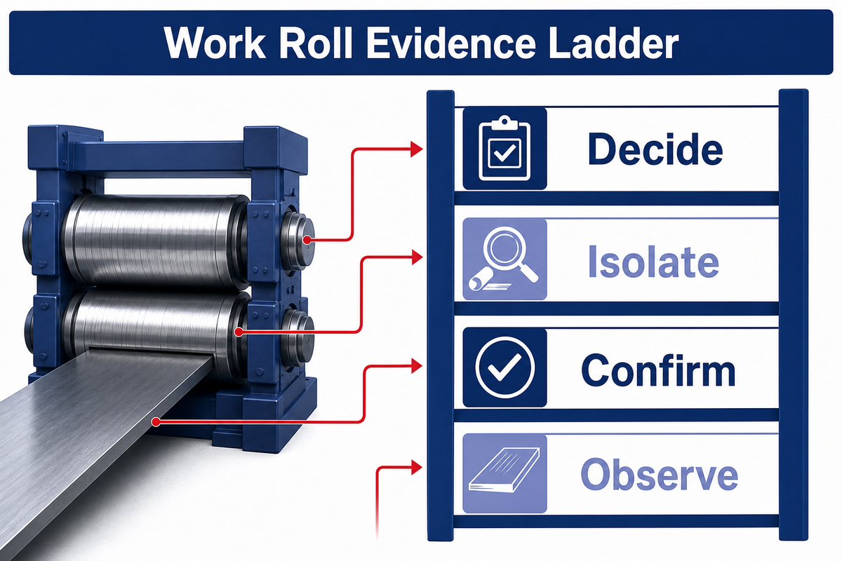
The 4-Step Work Roll Decision Framework, used here as the Work Roll Evidence Ladder, helps avoid a premature conclusion from an early indication. Each Step introduces a higher level of evidence and limits possible responses. The outcome depends on the quality of input. Stop and correct the record if the roll identity, dimensions or position is uncertain.
- Observe: define the strip or process symptom in measurable terms, location, pitch, width, time, speed and product.
- Confirm: test whether the clue matches roll circumference, barrel coordinate, profile, roughness, temperature history or vibration frequency.
- Isolate: review alternative causes, then inspect and measure the roll under the mill’s controlled isolation and handling procedure.
- Decide: choose clean, correct the process, regrind, test further, return to service or replace. Record who approved the outcome and what evidence was used to make that decision.
If a transverse band repeats at a pitch close to the work-roll circumference, treat it as a roll-side hypothesis rather than a replacement decision. Compare the band timing with line speed, see whether pitch changes with roll diameter, review vibration and cobble history, and inspect the matching barrel position. When physical evidence is absent but a drive frequency matches, investigate the alternative source.
Once we need application-specific material, hardness, profile, dimensions or mill compatibility, the informational task is complete. Now you can proceed to Welong’s Work Roll engineering and configuration page. Welong’s About Us page indicates the company started in 2001 and provides supplier development, purchasing oversight, and quality control; these don’t contribute evidence toward a universal roll outcome.
What Changed in Work Roll Research in 2025–2026?
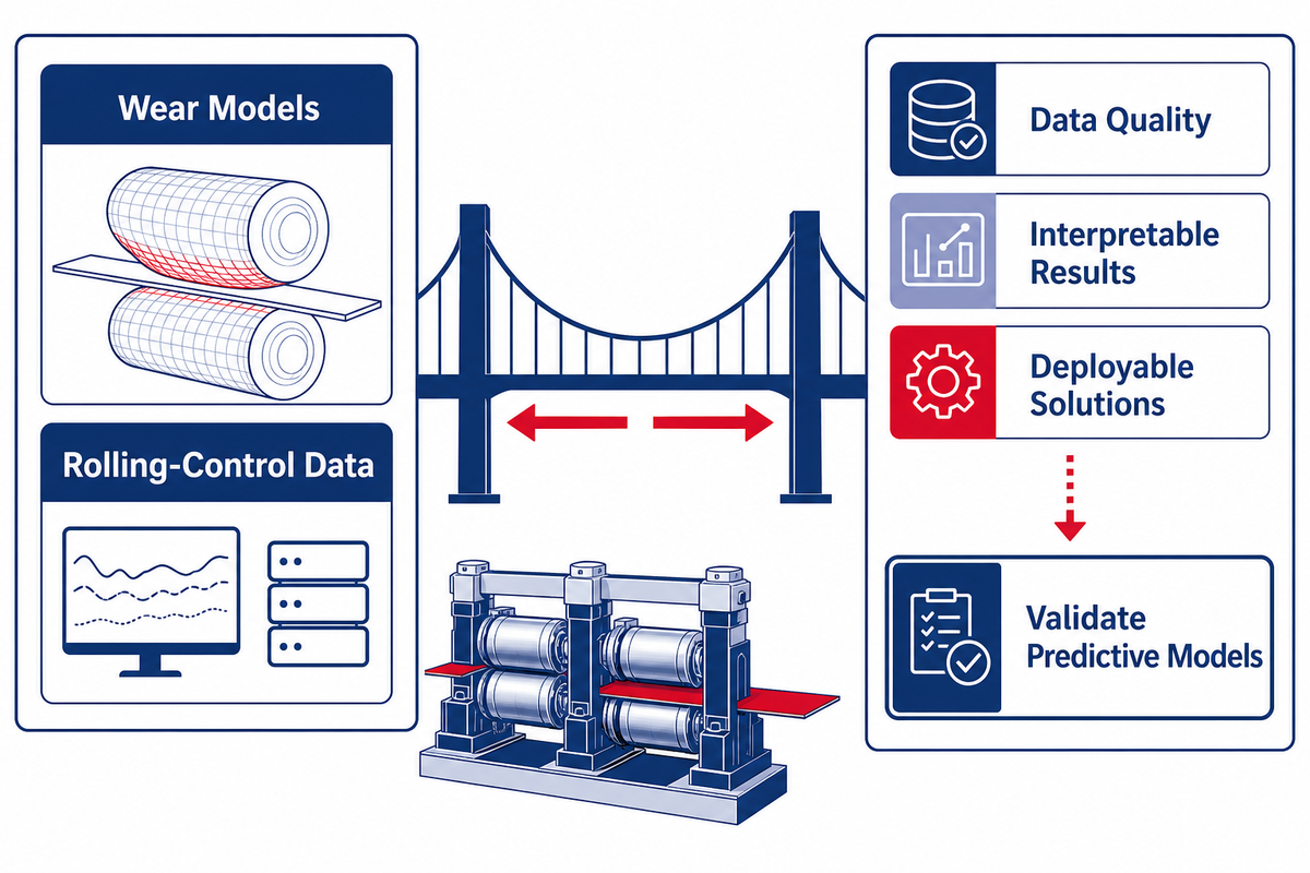
The improvement isn’t a forecast. Wear models integrate measurements and rolling-control data. A 2025 model combines elastic deformation, strip specifications and cumulative wear for work and backup rolls. Under its validation conditions, average deviation stayed within 0.01 mm; work- and backup-roll deviations were 0.012 and 0.004, with accuracy gains of 5.3% for uniform and 3.25% for mixed strip specifications. Authors also highlighted simplified thermal treatment, and incomplete adhesive and/or corrosive wear. Those limits matter as much as the accuracy.
A 2026 Frontiers review of AI in steel rolling mentions progress toward data-centered continuous optimization and control. The review also states the remaining challenges are data quality, interpretable results, and deployable solutions. For a mill, the first step is simple, but it can be valuable. Roll IDs, units, timestamps, stand coordinates, and event codes should be made consistent across all data. Predictive models can’t fill the gaps caused by inconsistent data.
The 2025 model’s sub-0.01 mm average deviation shouldn’t be viewed as an acceptance criterion. It’s a research result under specified conditions. Mills should validate predictive models against their own measurement systems, product portfolio and damage mechanisms before incorporating them into decision frameworks.
With those model limits established, the practical questions still return to component roles, evidence quality and mill-specific rules.
Frequently Asked Questions
What is the difference between a work roll and a backup roll?
The smaller work roll directly contacts the metal strip, so its loaded profile and surface condition affect thickness, shape and finish. Those monitoring advances do not change the basic mechanical distinction between the two rolls. Behind it, the backup roll limits bending under rolling load. They function as one stack, but inspection must distinguish strip-contact damage on the work roll from support-contact, alignment or load-distribution problems elsewhere.
How should a mill decide when to grind a work roll?
Combine campaign history with strip observations, roughness and profile measurements, crack or spall indications, vibration records, cooling events and remaining diameter. No universal tonnage number can account for stand, strip mix or abnormal events. The mill’s approved grind-removal and minimum-diameter rules remain controlling, and the evidence for each decision should stay with the roll record.
Can a strip defect prove that the work roll has failed?
No. Repeating marks or shape problems can point toward a work roll, but the strip is only the first evidence layer. Compare defect pitch and position with roll circumference and barrel location, review cooling, alignment, tension and vibration records, and inspect the isolated roll. If those observations don’t agree, continue the system investigation rather than forcing a roll diagnosis.
Which work roll material is best?
No family is best for every stand. Hot and cold rolling impose different thermal, fatigue, wear, texture and toughness demands. Evaluate the material, heat treatment, hardness profile and duty together; application-specific configuration belongs on the commercial page.
What should a work roll campaign record contain?
Record roll identity, stand and top/bottom position, drive/operator side, material family, starting and ending diameter, ground stock, campaign tonnage or length, rolled width and grade mix, planned reductions, roughness map, profile trace, cooling interruption, cobble, overload and vibration events, surface observations, nondestructive-test method and result, defect time and location, plus the final grind, return-to-service, hold or condemn disposition. Keep units, timestamps and barrel coordinates consistent. Name the person or function that approved the result so a later review can separate measured evidence from a shift note or assumption.
Need a Mill-Specific Work Roll Review?
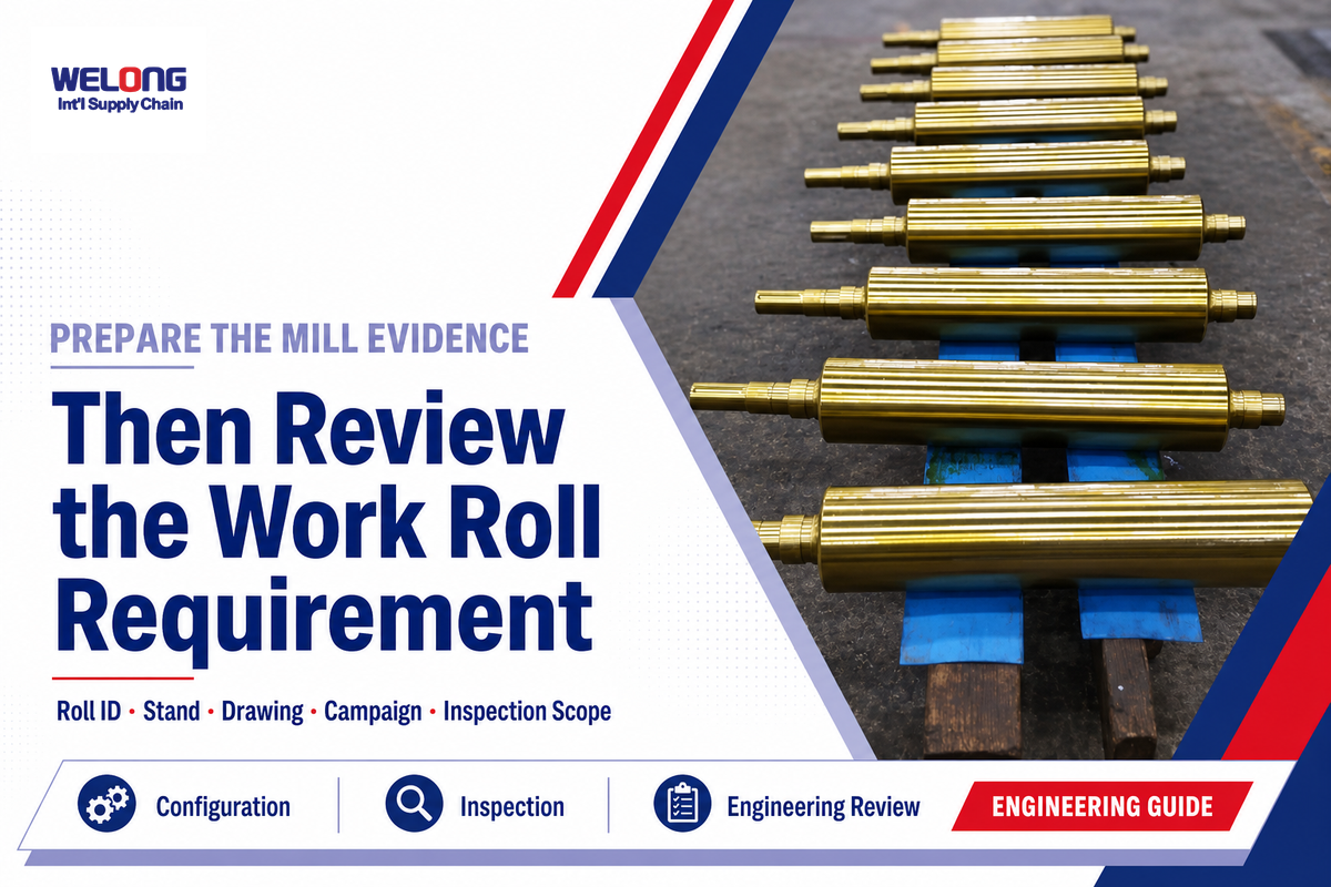
You should provide roll ID, stand, dimensions, material and a drawing, campaign history, surface findings, strip specifications, the results of acceptance checks, and required scope. Welong can use that record to discuss mill-specific work roll configuration and inspection requirements without replacing the mill’s engineering approval.
References & Sources
- Assessment of the Impact of Wear of the Working Surface of Rolls (Materials, 2022)
- Improvement in the Resistance to Wear of Work-Rolls Used in Hot Strip Mills (Metals, 2021)
- Temperature Field and Hot Roll Crown Model of Hot Continuous Rolling Mills (Metals, 2024)
- Wear Prediction Model for Hot Rolling Rolls (Metals, 2025)
- Analysis of Premature Failure of Work Rolls in a Cold Strip Plant (Wear)
- Steel Rolling in the Age of Artificial Intelligence: A Review (Frontiers in Materials, 2026)
- ICDP Work Roll Shell-Core Interface Spalling Case Study (2022)
- Surface Texturing from Skin-Pass Rolling to Final Forming (Lubricants, 2025)
Welong coordinates the sourcing of industrial materials and the control of their quality as described on its Welong industrial manufacturing website. Final roll placement, mill setting and safety controls are to be administered by the parties specified by the mill.
Why Buyers Work With Welong
About Welong Engineering Support
China Welong supports oilfield buyers with engineered supply-chain service for drilling tools, well-control equipment, rig-floor tools, casting parts, and industrial forged components.
Project Review Before RFQ
We help buyers compare tool family, material route, API or ISO requirements, inspection records, supplier capability, delivery risk, and documentation needs before a purchase decision is finalized.
Request An Oilfield QuoteCompany Profile // Data Sheet
CompanyChina Welong International Supply Chain
BrandWelong
CountryChina
Business TypeOilfield tools and industrial supply-chain partner
Main ProductsDownhole drilling tools, fishing and milling tools, wellhead and well-control equipment, oilfield hoses, rig-floor handling tools, mill rolls, and forgings
Engineering CapabilityTool-family selection, specification envelope review, API / ISO reference support, material traceability, inspection coordination, and supplier-route comparison
RFQ Data NeededTool type, size, connection, rating, grade, standard, quantity, drawings, and delivery target
Websitewelongoiltools.com
![Casing, Tubing & Drill Pipe Elevators [Field Guide]](https://welongoiltools.com/wp-content/uploads/2026/09/casing-tubing-drill-pipe-elevators-guide-featured-768x512.png)
![Choke & Kill Hose: [Field Guide]](https://welongoiltools.com/wp-content/uploads/2026/07/choke-kill-hose-guide-featured-1-150x150.png)