Get in touch with Welong Company

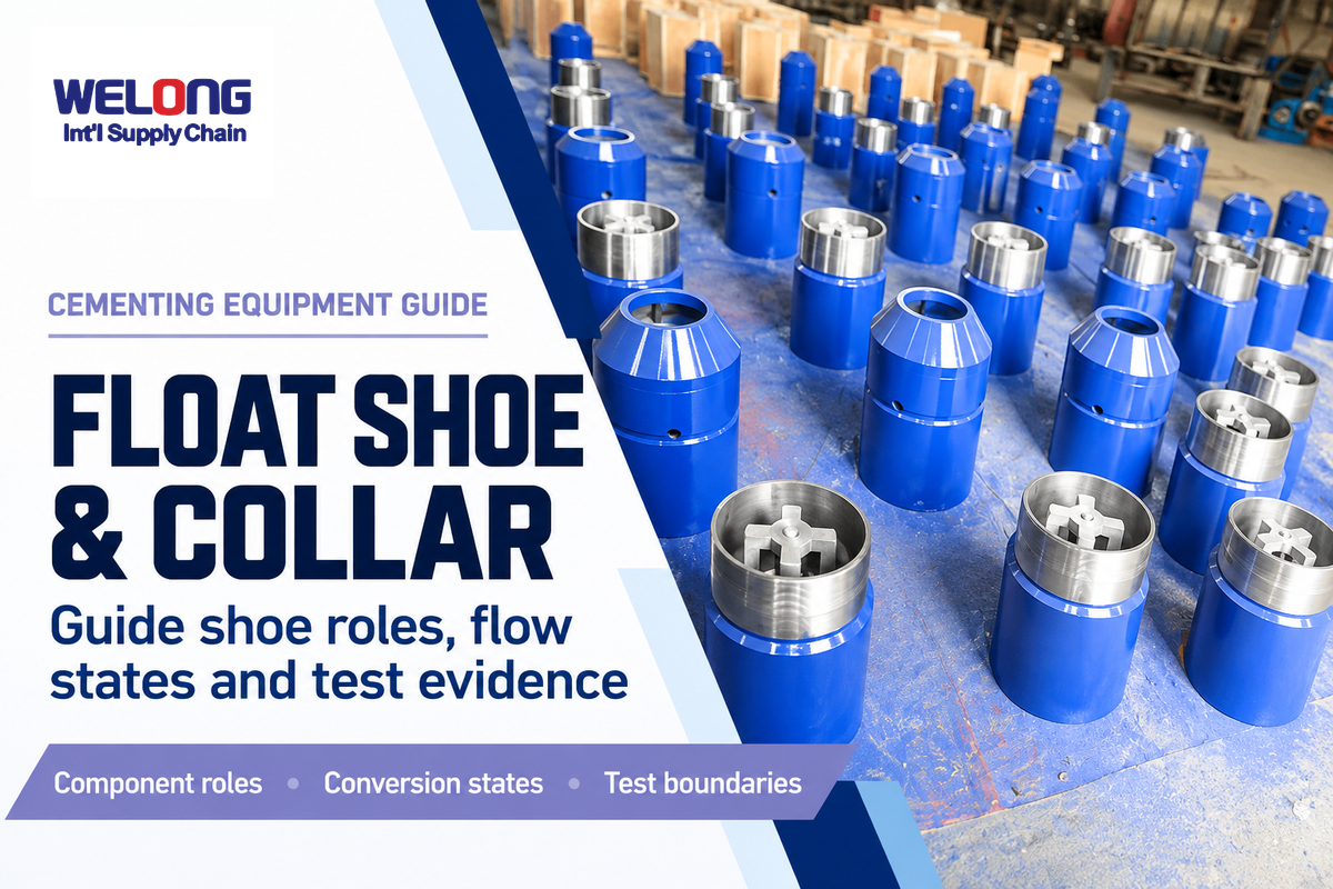
Float shoe, float collar, and guide shoe describe three jobs at the bottom of a casing string. Confusing guidance, plug landing and backflow control can leave a cementing program with the wrong equipment arrangement. First, identify the flow path, then compare the actual valve design and plug interface with the intended service.
Float Shoe, Float Collar & Guide Shoe: a float shoe combines a guiding nose with a check valve; a float collar provides a plug landing point and usually a check valve; a conventional guide shoe guides casing without a check valve.
Quick reference
- Valve count isn’t a pressure multiplier. A second valve adds redundancy.
- Location matters. The shoe is at the bottom; the collar is above it.
- Auto-fill has distinct states. Conversion follows the selected design.
- Qualification has boundaries. Test fluid, temperature and exposure belong beside the rating.
This guide explains the equipment and addresses the questions behind the technical specification. Approved well programs, manufacturer instructions and applicable well-control requirements govern field operations.
What Is the Difference Between a Float Shoe, Float Collar and Guide Shoe?
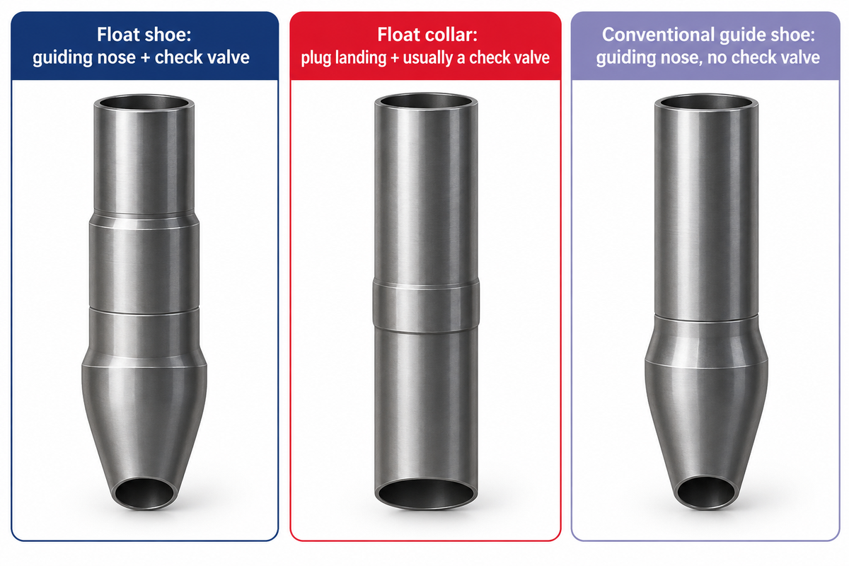
A float shoe guides the bottom of the casing and incorporates a check valve. A float collar is located above the shoe and receives cementing plugs and usually contains another valve. A conventional guide shoe has the guiding nose without a check valve, so the selected collar arrangement carries the backflow-control function.
The distinction is mechanical. A round or tapered nose helps guide casing past ledges and irregularities in the wellbore. A one-way valve controls fluid direction. A landing seat receives the matched plug. Although a float shoe and float collar may share a valve principle, their locations and interfaces differ.
Float-valve mechanisms can include a flapper, spring-loaded ball or other similar designs. In oil and gas casing cementing, the selected mechanism is dictated by the service downhole. The float collar is installed above the shoe, rather than being the guiding component at the bottom of the well.
| Feature | Float shoe | Float collar | Conventional guide shoe |
|---|---|---|---|
| Usual location | Lower end of casing | Above the shoe | Lower end of casing |
| Guiding nose | Yes, design-specific profile | Not its primary job | Yes |
| Check valve | Included | Usually included | Absent |
| Plug landing | Not a substitute for the specified landing assembly | Matched landing seat or profile | Not a float-collar landing assembly |
| Reverse-flow control | Valve function in its intended state | Valve function in its intended state | No independent check-valve function |
| Auto-fill option | Available in selected designs | Available in selected designs | An open path is not an auto-fill valve mechanism |
| Drill-out question | Internal materials and bit compatibility | Internals, plugs and anti-rotation features | Nose and internal materials |
| Connection question | Casing interface and tool dimensions | Casing coupling, bore and plug interface | Casing interface and nose dimensions |
| What it does not replace | Casing centralizers or an approved barrier design | Shoe guidance or an approved barrier design | A check valve |
Does a guide shoe plus a float collar provide two check valves?
No. A standard guide shoe adds no check valve. A single-valve collar adds one valve; a double-valve float collar adds two. A separate valve in the float shoe alters the situation again. Valve number, separation and shared exposure all belong on the assembly drawing.
In Applied Well Cementing Engineering, Sanchez adds that double valves add contingency rather than increase valve rating. Two valves placed close together can share a debris problem. For a customer presented an extra valve as an upgrade, a good question is which failure mode is addressed by the added valve.
Follow the Flow Path from Casing Running to Cement Placement
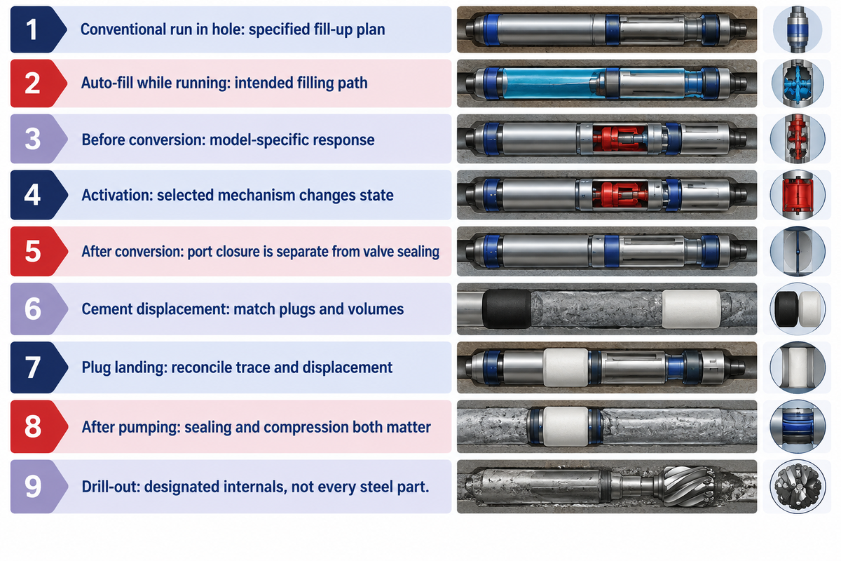
Conventional float equipment supports intended downward circulation and resists reverse flow through its check valve. Auto-fill float equipment opens a filling path during casing running and changes state through a design-specific conversion. Cement placement requires the intended converted arrangement, compatible plugs and a continuous displacement path through the shoe into the annulus.
During primary cementing operations, cement slurry moves down the casing and exits through the shoe before moving up, outside the pipe. Cement wiper plugs separate fluid stages and wipe the casing bore. The plug sequence and landing assembly control how that path changes; an observed pressure event must be evaluated in the context of the planned sequence.
Density differences between cement and drilling fluids create a hydrostatic pressure imbalance that can result in reverse flow. The valve counters that effect after conversion. Before the casing can run in the hole, its filling plan must agree with the selected valve state.
| State or event | Intended behavior | Meaning for the equipment review |
|---|---|---|
| Conventional run in hole | Check-valve arrangement limits reverse entry | Use the specified fill-up plan |
| Auto-fill while running casing | Fluid enters through the intended filling path | Open filling state is deliberate |
| Circulation before conversion | Design may retain or deactivate auto-fill | The precise model determines the response |
| Activation event | Ball, sleeve or other mechanism changes state | Use the model-specific sequence and acceptance method |
| Post-conversion circulation | Flow follows the converted path | Port closure and valve sealing are separate functions |
| Cement displacement | Slurry moves toward the casing shoe | Plug interfaces and volumes must match the program |
| Plug landing | The designated plug reaches its landing point | Interpret the trace alongside the displacement record |
| After pumping stops | Converted float valves hold back pressure within their rated service | Fluid compression and seal condition affect interpretation |
| Drill-out | The chosen bit removes designated internals and cement | Drillable does not describe every steel part of the assembly |
Which flow direction changes when auto-fill equipment converts?
The filling path that allows fluid entry during running is closed or altered, thereby preserving the intended circulation and check-valve functions. Conversion is a mechanical state change, and not merely attaining a specific depth. Therefore, for a conventional check valve and a convertible filling assembly, different instructions for running-in and circulation are required.
Example: A planning team replaces a standard float arrangement with an auto-fill float collar to lessen fill-up interruptions. While the drawing retains the original plug assembly, the running-in instruction omits the activation mechanism. The purchaser has selected the feature without describing how its state changes. The correction is to resolve the conversion sequence and plug passage together before the package is released. A higher pressure figure on the purchase order would leave that interface problem unresolved. A clean equipment list needs both the hardware identities and the intended flow state at each stage of the job.
What Happens Between the Float Collar and the Casing Shoe?
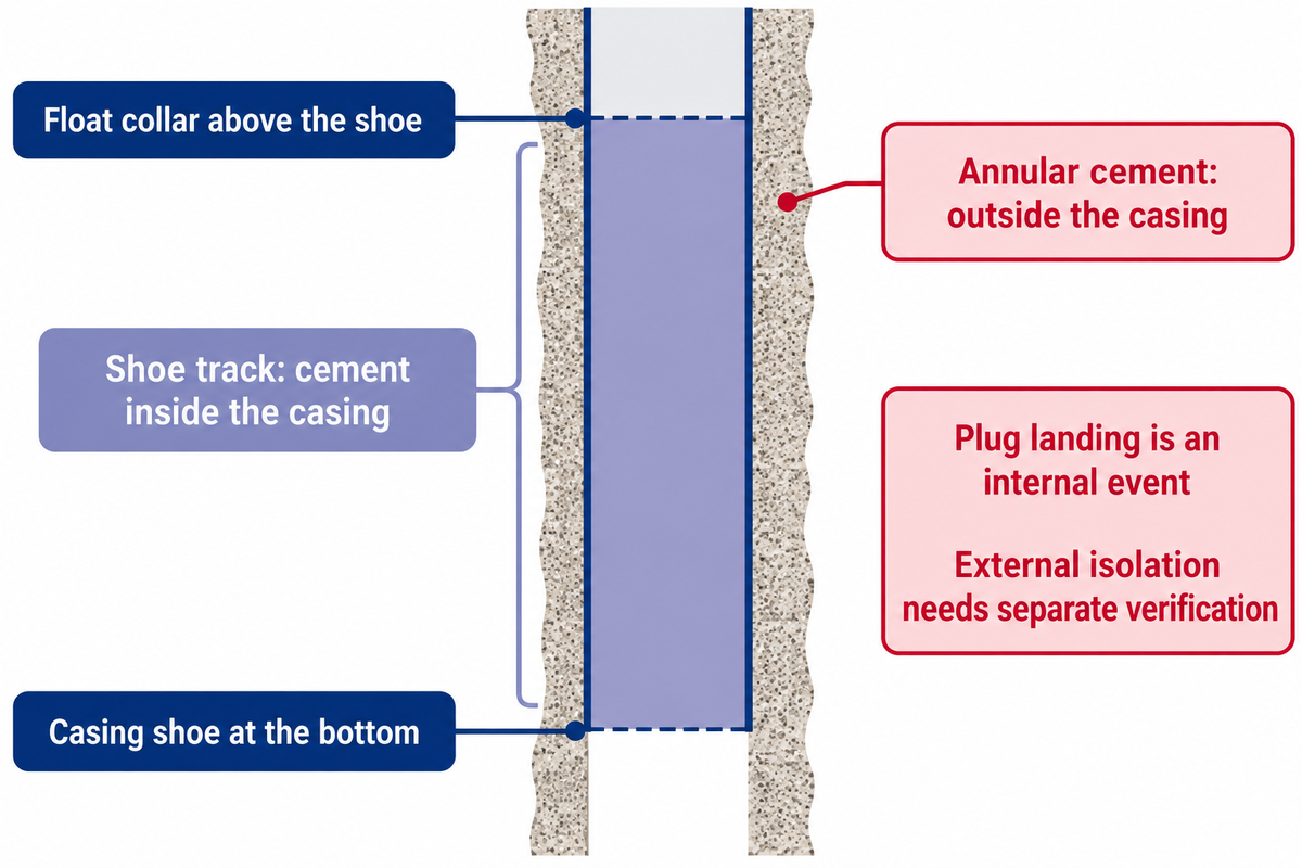
The shoe track is the casing interval below the float collar that retains a buffer of cement near the shoe. This buffer reduces the risk of over displacement bringing contaminated fluid into the annular cement column. Its length follows the casing and cementing design, rather than a universal number of casing joints.
Descriptions often place the collar one or more joints above the float shoe. SLB gives examples of one, two or three joints. These examples are geometrical, and don’t choose the appropriate buffer for every intermediate casing or production string. Internal volume, slurry interfaces, plug behavior, and displacement uncertainty affect the choice.
Internal shoe-track cement and annular cement occupy different flow paths. A plug landing on the float collar indicates an event in the casing. Isolation outside the casing requires its own design and verification. Casing centralizer placement and standoff address another part of that external placement problem.
This description of Halliburton’s GasVault deals with wet-shoe track containing little cement or contaminated cement. Its proposed gas-tight float barrier is an example of a named product approach to this situation. The wet-shoe case has to be treated separately from a conventional cement filled-interval. The term does not turn every float valve into a qualified well barrier.
For wells located on the U.S. Outer Continental Shelf, within 30 CFR 250.420(b)(3), the rule says that independent barriers are needed for wells using subsea blowout-preventer stacks, and states that a dual float valve alone isn’t considered a mechanical barrier. Component redundancy and regulatory barrier qualification are separate decisions.
Therefore, a proposed shoe-track reduction belongs in the well-design review. Saving casing length isn’t the same as accepting the associated uncertainty and barrier arrangement.
Why Does Auto-Fill Equipment Need a Verified Conversion Sequence?
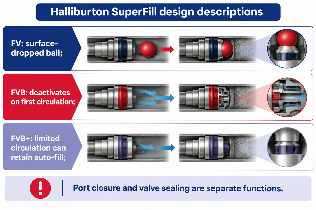
Auto-fill equipment needs a defined conversion sequence because the open filling function and the post-conversion check-valve function use different internal states. A sequence written for one auto-fill float assembly can change another assembly prematurely or leave the required conversion unresolved.
Halliburton’s SuperFill descriptions make the situation clear. Type FV uses a surface-dropped ball. Type FVB retains the ball in the collar and deactivates auto-fill on first circulation. Type FVB+ permits limited circulation while retaining auto-fill capability. The same instruction to circulate has different meanings.
For auto/differential fill, how will conversion or valve status be verified before cement displacement?
The activation event and acceptance criterion of the selected model must be applied to the actual ball, flow path and assembly; pressure change and diverter port closure are different observations. A pressure change in level alone is inadequate to describe conversion. Confirmation that a diverter port has closed also concerns that port; the acceptance plan must address the intended float-valve function separately.
The Macondo Case Study illustrates the importance of the mechanism. The National Commission discussed a flow-induced conversion design and uncertainty about interpreting a pressure drop. The lesson is to relate the observation to the moving part and the flow condition intended and required for the conversion, as opposed to borrowing a different incident’s pressure drop numbers as a command.
An example is illustrative. Example: An engineer intends to wash past a restriction before he reaches the setting depth. The offer says auto-fill, while the running plan assumes circulation can happen without conversion. Comparing an FVB type response with an FVB+ type response shows the missing decision on whether that circulation is intended to de-activate filling. The team settles on the correct model and establishes the correct sequence before shipment. Procurement records the selected revision with the assembly drawing, so a substitute carrying the same generic description cannot silently change the running behavior. No universal activation pressure or rate can repair a mismatch between those two intended operating states.
Expro’s ULTRASEAL page similarly describes three selectable flow settings, including no flow, low flow and high flow, plus trapped or surface-dropped activation options. These are Expro’s features. In Halliburton’s Africa case, a SuperFill II BigBore FVB+ collar is paired with a guide shoe. Neither configuration makes every auto-fill tool interchangeable.
Read a Float-Equipment Test Report Against the Intended Well
Useful reviews of float equipment tests relate the specimen and test sequence to the service. Pressure alone is insufficient: Other considerations are medium, temperature, erosion exposure, valve arrangement, and acceptance criteria. Start with complete model-specific records, and separate demonstrated conditions from requirements of the well design.
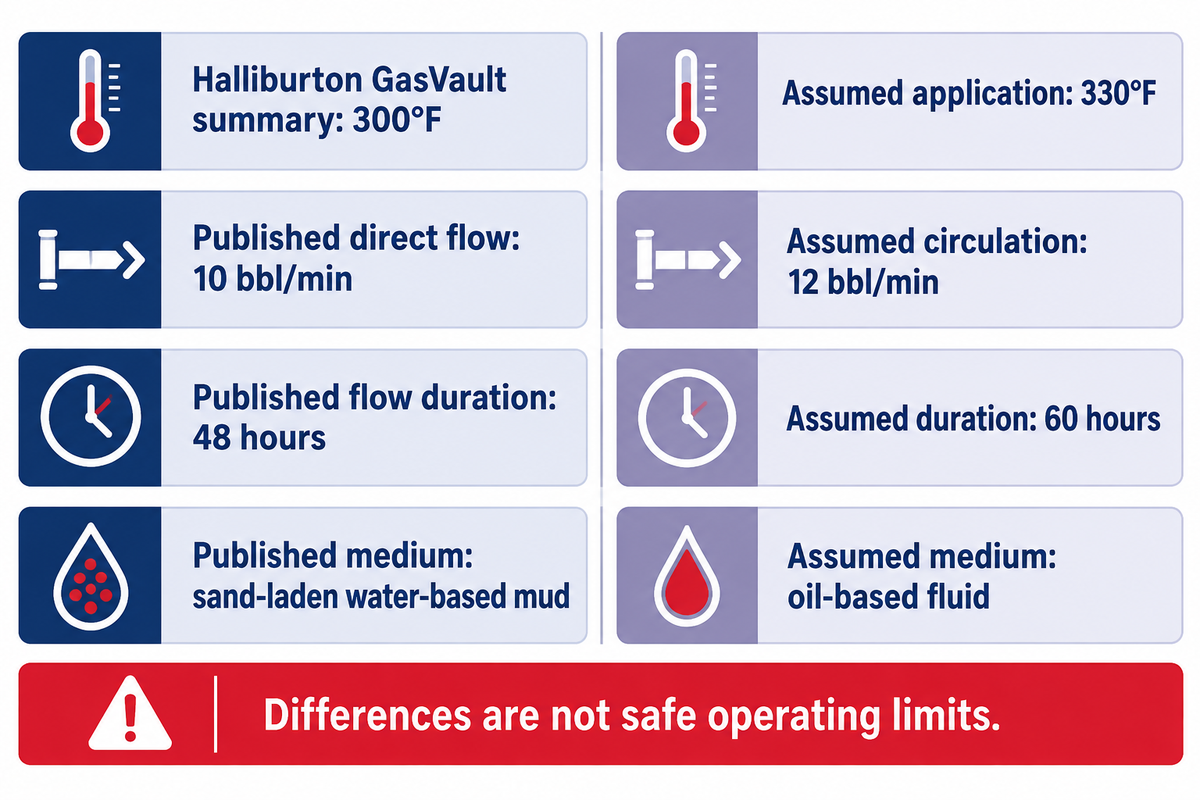
Consider a real, publicly reported benchmark. Halliburton reports GasVault gas testing to 5,500 psi and fluid testing to 15,000 psi at 300°F, after 48 hours of direct flow at 10 bbl/min with sand-laden water-based mud. Those figures describe Halliburton’s published product-test summary, not China Welong ratings or field setpoints.
Let’s assume the target conditions. Example, assumed target conditions: a purchasing team compares that summary with an oil-based-fluid application at 330°F, with planned circulation of 12 bbl/min for 60 hours. The largest printed liquid pressure number attracts the most attention. However, the application differs from the summary in four other dimensions. The engineer identifies the medium and exposure differences; quality assurance needs the specimen identity and original results; procurement keeps the offer conditional on resolving those gaps. Finance avoids treating an incomplete technical comparison as a finished purchase decision. The outcome is a focused request for qualification evidence, rather than acceptance based on one headline pressure rating.
| Review dimension | Halliburton GasVault published summary | Assumed job or review need | Decision |
|---|---|---|---|
| Gas pressure | 5,500 psi | Gas-sealing requirement must be specified | Compare gas duty with gas-test evidence |
| Liquid pressure | 15,000 psi | Required differential and direction | Keep separate from the gas figure |
| Temperature | 300°F | 330°F | 30°F above the cited condition |
| Direct-flow rate | 10 bbl/min | 12 bbl/min | 2 bbl/min above the cited rate |
| Flow duration | 48 hours | 60 hours | 12 hours beyond the cited exposure |
| Test medium | Sand-laden water-based mud | Oil-based fluid | Different medium; review material and sealing behavior |
| Specimen identity | Named product family in public summary | Exact offered model and revision | Match the original report to the offer |
| Valve arrangement | Original test record required for full detail | Selected number and arrangement | Match the tested assembly |
| Acceptance criteria | Headline test values | Recorded leakage criteria and results | Review the complete qualification package |
| Delivery identity | Product description | Order, inspection and traceability records | Connect the qualified design to delivered equipment |
The arithmetic identifies differences; it doesn’t calculate a safe operating limit. In the example, 330°F minus 300°F gives a 30°F temperature gap, while 60 minus 48 gives 12 additional hours of exposure. Adding a larger pressure headline does not account for either difference. High flow rates and long exposure also belong in the erosion review, rather than being replaced by a static pressure comparison.
ISO 10427-3:2003 applies to equipment in contact with water-based drilling and cementing fluids; it excludes performance in non-water-based fluids. Keep that stated ISO boundary attached to the test discussion rather than automatically extending it to every API Specification 10F claim.
How can an API 7-1 certificate be confused with float-equipment test evidence?
The confusion occurs when a company-level credential is substituted for the offered float tool’s test record. API 7-1 covers rotary drill stem elements. Float equipment needs the applicable model-specific specification and qualification records. A familiar logo on the supplier profile doesn’t change the product scope of the cited document.
The Accuris catalog reviewed for this guide lists API Spec 10F (R2026), Fourth Edition, dated July 2018, with 2020 Errata 1 and Errata 2, as the current edition. Those are publication metadata. The complete applicable standard and original test records should be in the technical package with the cementing-tools standards coverage lookup.
Investigate Backflow, Plug-Landing and Drill-Out Problems
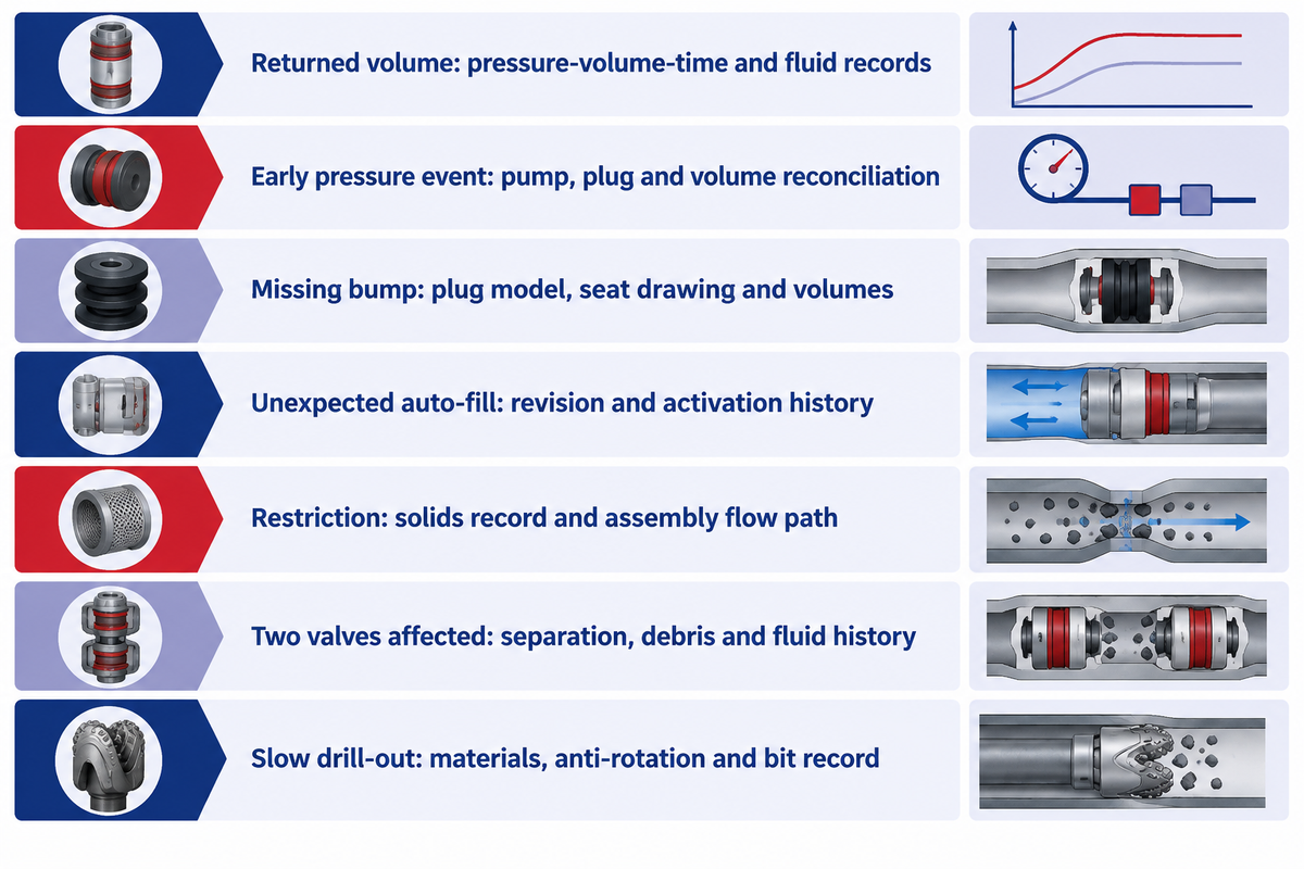
Backflow, an unexpected pressure response and a missing plug bump describe observations rather than one unique failure. The pressure trace, the displacement record, fluid properties, and the plug sequence are required to investigate them. In general, cementing observations must be separated from formal integrity-test results, since the context of the test changes both the interpretation and the required action.
Fluids are volume-compressible under pressure, and this may contribute to a returned volume without necessarily identifying a failed check valve. Debris, an incomplete conversion, a plug interface problem, or another flow path may contribute to similar observations. A pressure curve becomes useful when aligned with the actual fluid and hardware sequence.
“sometimes a perceived float equipment failure is simply the result of underestimating fluid compression.”
| Observation | Competing explanation to investigate | Record needed |
|---|---|---|
| Returned volume after pressure release | Compression response or a leaking path | Pressure-volume-time trace and fluid properties |
| Pressure event before expected landing | Restriction or an earlier sequence event | Pump record, plug release and volume reconciliation |
| Expected bump absent | Plug travel, landing interface or displacement discrepancy | Actual plug model, seat drawing and delivered volumes |
| Auto-fill response unexpected | Conversion state differs from the plan | Tool revision and activation history |
| Flow restriction increases | Debris, solids loading or restricted passage | Mud/solids record and assembly flow path |
| Two valves respond poorly | Shared exposure rather than two unrelated defects | Valve separation, debris and fluid history |
| Drill-out takes longer | Internal material, plug rotation or bit mismatch | Material list, anti-rotation arrangement and drilling record |
A May 2024 oilfield-worker discussion about cement left in pipe illustrates the information gap. Contributors sought clarification about pressure charts, displacement volumes and the plug/dart sequence. The discussion did not establish a confirmed root cause. Its practical value is the record set it identifies, rather than an anonymous diagnosis.
For U.S. offshore wells covered by 30 CFR 250.721(g), including the specified subsea-BOP or mudline-suspension systems, indications of a failed negative pressure test such as pressure buildup or observed flow require immediate investigation. A general compression explanation must never normalize those test anomalies.
The 2011 U.S. investigation testimony discusses a failed cement barrier and multiple contributors at Macondo, with uncertainty about the precise cement-job failure mechanism. Treating that event as a single-float failure would erase the investigation’s central lesson about interacting decisions and misinterpreted observations.
Drill-out plans should precede the purchase decision. Material-specific compatibility with a PDC drill bit concerns the designated internals and plugs; steel housings and casing still have their own roles.
Turn Engineering Unknowns into a Documented Technical Enquiry
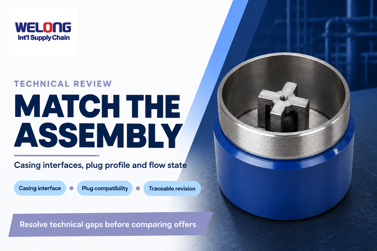
A useful enquiry gives the supplier an identifiable casing program, required flow states and acceptance records. It connects the well engineer’s service conditions with quality assurance’s traceability requirements and procurement’s delivery scope. That makes alternative offers comparable before a price difference hides a different valve, plug profile or test basis.
Do casing size, connection, drift ID, float-tool OD, and cementing plugs match?
They must match as a complete assembly, including the smallest passage and the intended plug landing profile. Nominal casing size doesn’t resolve connection, wall thickness, and internal clearance. Burst and collapse resistance of the casing also remain separate from the internal float valve’s sealing and flow-performance ratings.
- Identify casing size, weight, grade, connection and drift requirements.
- Specify tool model, revision, valve arrangement and intended filling/conversion states.
- Provide fluid system, solids or lost-circulation-material exposure, temperature and pressure duties.
- Match cement plugs, darts, seats and the planned drill-out assembly.
- Request the applicable standard edition, original qualification record and delivery inspection/traceability documents.
Use the casing program package builder to organize the inquiry. China Welong, founded in 2001, provides integrated supply chain services for oilfield and customized products. Its float equipment solutions page is the next step for a product-specific supply discussion.
Check the Design and Verification Package Before Release
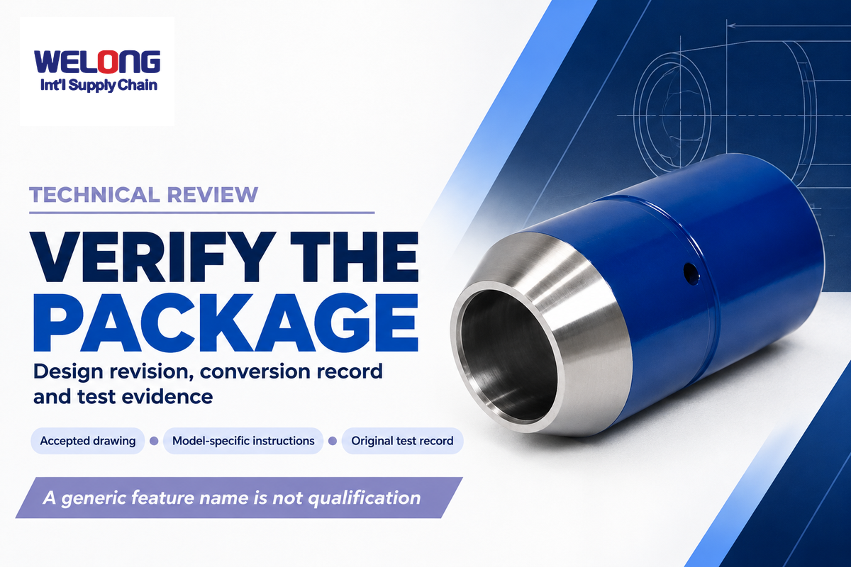
Release the package against the selected design revision, and not against a generic innovation claim. US6679336B2, published in 2004, already describes multiple filling and jetting functions; its displayed applicant is Davis Lynch and its listed current assignee is Forum US, rather than Welong.
A reamer shoe, guiding nose, valve cartridge and plug assembly each need the intended function on the drawing. Match that drawing to conversion instructions, and check the test package and order records. A high flow area or a choice of activation settings is useful only when it resolves the actual running and cementing requirement. Keep the accepted revision with the purchase scope.
Frequently Asked Questions
What is a guide shoe in casing?
A guide shoe is a shaped component fitted to the bottom of a casing string to help the pipe pass ledges and irregularities. A conventional guide shoe has no check valve. Its nose and internal materials can include drillable parts, while its guiding function remains separate from the float collar’s valve and plug-landing functions.
What is a float collar used for?
A float collar provides the intended landing point for cementing plugs near the lower end of the casing and usually incorporates a check valve. After the appropriate operating-state transition, that valve resists reverse flow. Collar position also defines the upper end of the shoe track, so plug compatibility and the planned retained cement volume belong in its specification.
What is the function of a float shoe?
A float shoe combines a casing-guiding nose with a valve that permits intended forward flow and resists reverse flow. It’s fitted at the lower end of the casing. The selected design may have conventional or convertible filling behavior, so its running state and conversion method must be identified rather than inferred from the word float.
How many casing joints should be below the float collar?
There’s no universal joint count for every well. Common descriptions use one, two or three joints; the actual shoe-track length follows the cementing design, internal volume and displacement uncertainty.
Are float shoes and collars PDC drillable?
Many designs have PDC-drillable internals, but the specific materials, plugs and anti-rotation features determine compatibility. Drillable internals don’t mean that every steel component is intended to be drilled away. The planned bit and drill-out procedure must suit the selected assembly.
Does a double-valve float collar have a higher pressure rating?
No automatic increase follows from adding a valve. The second valve provides redundancy; the rated pressure remains a property of the qualified design and test conditions, not the sum of two valve ratings.
What is the purpose of auto-fill float equipment?
Auto-fill equipment lets fluid enter the casing during running to reduce filling interruptions and manage surge pressure. It then converts to the intended cementing state through its specific activation mechanism. Some designs convert on first circulation, while others permit limited circulation before deactivation, so that distinction belongs in the running plan.
Prepare the assembly before comparing offers. Start with the casing and plug interfaces, define the intended flow states, then attach the qualification and traceability requirements to the selected model.
This educational guide includes public definitions from the glossary, manufacturer’s product descriptions, a cementing excerpt, and specified regulation. Examples of manufacturers retain their names. Assumed inputs were used for the worked examples; this article isn’t a field procedure or a China Welong product certification.
References & Sources
- SLB glossary: guide shoe; float collar; shoe track.
- Halliburton: GasVault float-valve test summary; SuperFill design descriptions; Africa campaign case study.
- Expro: ULTRASEAL auto-fill features.
- ISO 10427-3:2003 public abstract; API licensing information and product scopes; Accuris API Spec 10F catalog metadata.
- Alfredo Sanchez, Applied Well Cementing Engineering (2021), Casing equipment excerpt.
- Farley, Barannikow and Bourg, Offshore, April 18, 2016.
- 30 CFR 250.420(b)(3); 30 CFR 250.721(g); DOI investigation testimony, October 13, 2011.
- National Commission, Deep Water (2011), page 116, UNT Digital Library.
- US6679336B2: Multi-purpose float equipment and method (2004).