
Get in touch with Welong Company


A PDC Drill Bit is a fixed-cutter drilling tool that removes rock with polycrystalline diamond compact cutters mounted on blades. The cutters travel across the bottom of the hole and shear the formation rather than relying on rotating cones to crush it. That simple definition explains the cutting action, but it doesn’t explain why one run is smooth and efficient while another develops low penetration, erratic torque, vibration, or damaged cutters.
Direct answer
PDC stands for polycrystalline diamond compact. A PDC bit has no moving cones or bearings; fixed cutters shear rock as the bit rotates. Performance depends on the interval, cutting structure, cleaning and cooling, and drilling-system dynamics. A change in one surface signal is a reason to investigate, not proof that the bit is dull.
What this guide does differently
- It treats formation, cutting structure, hydraulics, and dynamics as one connected drilling system.
- It separates an observed change from the failure cause someone may infer from it.
- It provides a Four-Lens PDC Run Review and a copyable evidence sheet for the next decision.
- It leaves product configurations, availability, pricing, and quotation intent on the PDC Drill Bit solution page.
How Does a PDC Drill Bit Cut Rock?
A PDC cutter presents a hard diamond table to the formation. As the bit turns, the cutter moves laterally through the rock and removes material by shearing. Weight on bit helps establish depth of cut; rotation supplies cutting speed; hydraulics clear the fragments and cool the cutting structure.
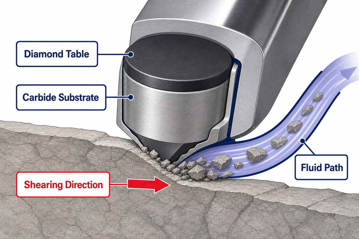
The diamond table is bonded to a tungsten carbide substrate that supports it and allows the cutter assembly to be mounted in the blade. Blade profile, cutter placement, back rake, exposure, gauge contact, and the number of cutters sharing the load all influence how the bit engages the formation. Those details are part of a design system, so “more aggressive” isn’t automatically “better.” A design that produces a high depth of cut may also require higher torque or become less stable in a severe transition.
The SLB technical history of drill bits distinguishes this continuous shearing action from the gouging and crushing of roller cone bits. It also shows the basic fluid path: nozzles direct drilling fluid toward the formation, while fluid courses and junk slots create routes for cuttings to exit the bit face.
Key takeaway
The cutter does not work alone. A capable cutting structure can still underperform if the bottom is not cleaned, the interval changes, or the drilling system cannot keep the bit stable.
Read a PDC Bit as Four Connected Systems
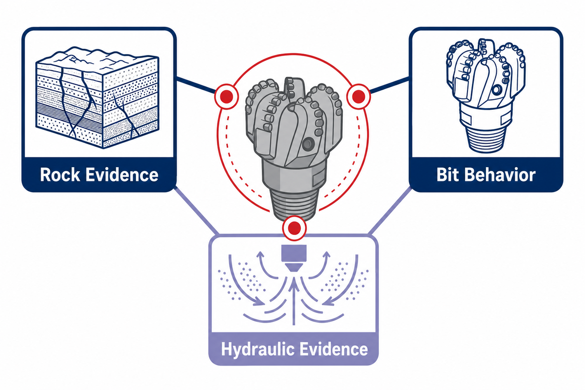
A good review employs four perspectives: the rock being drilled, the cutting structure contacting it, the hydraulic system cleaning and cooling the face, and the drilling system providing weight, rotation, and directional control. Surface behavior is the aggregate of all four.
Lens 1 · Rock
Strength, abrasivity, plasticity, bedding, fractures, and the severity of transitions.
Lens 2 · Cutting
Cutter geometry and exposure, blade profile, gauge contact, load sharing, and damage location.
Lens 3 · Hydraulics
Nozzle condition, face cleaning, cuttings evacuation, fluid behavior, and cutter cooling.
Lens 4 · Dynamics
WOB, RPM, torque, stick-slip, lateral vibration, whirl, BHA behavior, and directional demand.
Cutting structure and body are not separate decisions
A steel body is ductile and may support design features such as taller blades or larger flow areas, while a tungsten-carbide matrix body offers greater erosion and abrasion resistance but is more brittle. Those are technical tradeoffs, not a two-row shopping rule. The right body and blade geometry depend on the entire application, repair plan, hydraulic layout, and expected damage mechanism. Specific configurations belong in an application review, not in a general guide.
Hydraulics are part of the cutting mechanism
A US Department of Energy technical record on PDC-bit hydraulics identifies bottomhole scavenging, chip removal, bit cleaning, and cutter cooling as core hydraulic functions. If cuttings remain under the blades, cutters may recut debris instead of engaging fresh rock. If a sticky formation packs the face, low ROP and higher torque can appear even when the cutters beneath the packed material remain serviceable.
The reverse is also true: a clean-looking bit after a long trip doesn’t prove that cleaning was adequate while drilling. Keep pressure, flow, returns, mud-property, and cuttings observations on the run timeline instead of relying only on the final photograph.
Rock, Bit–Hydraulics Fit Map
Formation names are starting context, not final bit-selection instructions. A fit map asks what the rock is likely to do, which part of the PDC system is exposed to risk, and what evidence is needed before a configuration decision.
| Interval context | PDC opportunity | Primary risk to test | Evidence needed | Boundary question |
|---|---|---|---|---|
| Soft or plastic | Efficient continuous shearing can support high penetration. | Bit balling, packed cuttings, and restricted flow paths. | Mud behavior, flow/pressure, returns, cuttings shape, and cleaned face condition. | Can hydraulics keep the cutting structure exposed? |
| Competent and reasonably homogeneous | Stable engagement can convert rotation into consistent shearing. | Excessive depth of cut, torque demand, thermal wear, or stability loss. | Offset response, WOB/RPM window, torque, vibration, and cutter wear location. | Can the BHA and drive system keep engagement stable? |
| Abrasive | PDC wear resistance may support long footage when design and cooling fit. | Progressive cutter wear, gauge loss, and body erosion. | Wear progression, cuttings/mineral context, gauge measurement, and hydraulic condition. | Is durability or aggressiveness the controlling objective? |
| Interbedded or transitional | A stable design may still maintain useful penetration across layers. | Impact loading, stick-slip, lateral vibration, and localized cutter damage. | Transition depths, high-frequency events where available, surface torque, and damage by bit zone. | Would a less aggressive, more stable, roller-cone, or hybrid response be safer? |
| Fractured or impact-prone | Application-specific PDC designs may remain viable. | Chipped, broken, spalled, or lost cutters after intermittent loading. | Event timing, BHA behavior, cutter damage direction/location, and formation evidence. | Does the drilling system control impact well enough for fixed cutters? |
Application labels do not make evidence interchangeable
Search results often place oil and gas drilling beside horizontal directional drilling (HDD), geothermal well drilling, mining, casing work, and reamer applications. These are different drilling applications with different drilling equipment, BHA behavior, borehole objectives, and operating limits. The same phrase, PDC bit technology, doesn’t make their data portable. Use geological context and machine-specific baselines before applying a drilling performance lesson from one application to another.
Even within rotary oil and gas work, shale, sandstone, limestone, soft to medium-hard rock formations, hard and abrasive formations, and interbedded formations expose different drilling challenges. Bits are designed around a particular balance of aggressiveness, stability, wear resistance, directional control, and cuttings evacuation. Drilling through hard transitions may call for different cutter technology, blade loading, body toughness, or hydraulic priorities than a long homogeneous interval.
That is also why claims such as “faster drilling,” “reliable performance,” “longer bit life,” or lower drilling costs need an offset and an operating boundary. Penetration rates and performance improvements only become useful when the formation, drive system, fluid program, and run objective are comparable. The development process should optimize the complete system rather than chase rate of penetration alone, and neither a high-strength steel body nor a matrix composite guarantees longevity or lifespan without application evidence.
This map isn’t a model selector. It’s a question generator. If you’re ready to evaluate specific conditions, use the site’s PDC bit selection advisor and carry the evidence listed above into the discussion.
PDC vs Tricone: Compare the Failure Boundary, Not Just ROP
PDC bits use fixed cutters to shear, while tricone bits use rotating cones to gouge, crush, and chip. PDC eliminates cone bearings and can provide continuous cutting, but fixed cutters can be sensitive to cleaning limits, torsional instability, lateral motion, and impact at severe transitions. The useful question is which failure boundary fits the interval and drilling system.
A roller cone bit introduces moving cones, bearings, and a different contact pattern. That may trade continuous shearing efficiency for a rock-breaking response better suited to some hard, variable, or impact-prone formations. Neither family wins from the name alone. Examine interval variability, abrasivity, cleaning, directional response, rig limits, expected footage, and the cost of an unplanned trip.
Use the dedicated tricone versus PDC decision guide for a side-by-side decision path, or review the Tricone Drill Bit page when the interval points toward roller-cone options.
Live-Signal Triage: A Signal Is an Observation, Not a Failure Mode
ROP, torque, vibration, standpipe pressure, returns, and cuttings can reveal that the system changed. They don’t identify one cause by themselves. First ask what changed at the same time: formation, WOB, RPM, flow, mud properties, directional mode, or hole condition.
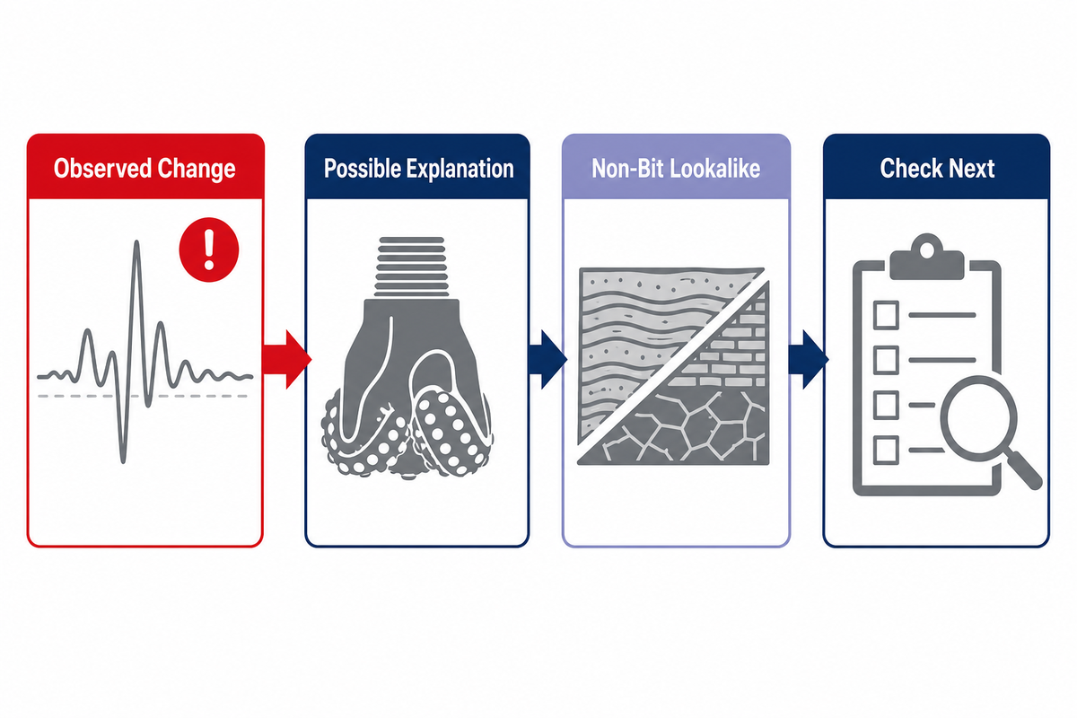
National-laboratory research has associated PDC cutter impact damage with dynamic instability including bit bounce, whirl, and stick-slip. That supports monitoring dynamics, but it doesn’t create a universal threshold. Sensor placement, rig/BHA configuration, sampling rate, formation, operating window, and the bit design all affect what a signal means.
| Observed change | Possible bit-related explanation | Non-bit lookalike | Check next |
|---|---|---|---|
| ROP falls gradually | Progressive cutter wear, reduced depth of cut, or cleaning deterioration. | Increasing strength or abrasivity, input change, or hole-cleaning constraint. | Formation timeline, WOB/RPM, torque, hydraulics, and final wear flats. |
| Torque rises or oscillates | Unstable cutter engagement, balling, or localized damage may be developing. | Directional mode, contact/friction change, lithology transition, or motor response. | Depth-aligned recurrence, RPM behavior, returns, and damage location. |
| Vibration increases | Whirl, stick-slip, bit bounce, or asymmetric engagement may threaten cutters. | BHA/formation interaction or an operating-parameter change. | Identify axial, torsional, or lateral character where measured; correlate with events and pulled-bit damage. |
| Standpipe pressure changes | Nozzle restriction, packed flow path, or erosion may affect the bit. | Mud-property, flow-rate, tool, or annular change elsewhere. | Pump/flow record, nozzles, junk slots, circulation events, and returns. |
| Cuttings character changes | Depth of cut or shearing efficiency may have changed. | Lithology, transport, residence time, or sampling practice changed. | Depth lag, lithology, operating inputs, shaker observations, and other response signals. |
| Abrupt change at a boundary | The new layer may expose a stability or impact limit. | The formation change alone explains the new response. | Persistence after the boundary, event severity, and physical damage aligned to that depth. |
Do
- Synchronize data by time and depth.
- Keep formation and input changes next to the response.
- State a competing explanation and the next check.
Don’t
- Turn one spike into a universal threshold.
- Diagnose a cutter from surface data alone.
- Hide conflicting evidence to make the conclusion look cleaner.
The Four-Lens PDC Run Review
The Four-Lens PDC Run Review aligns the formation timeline, drilling response, hydraulic evidence, and physical bit condition. One lens creates a hypothesis. Two lenses that agree prioritize a check. A strong conclusion needs physical evidence that fits the time/depth record, while conflicting evidence stays marked as unresolved.
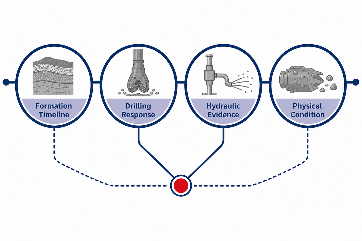
- Build the formation timeline – note known lithology, strength or abrasivity changes, fractures, and transition depths. Mark uncertainty where the log is inferred rather than confirmed.
- Overlay the drilling response — align ROP, WOB, RPM, torque, vibration, directional mode, and intentional parameter changes. Preserve the baseline before the event.
- Add hydraulics and returns – track flow and pressure shifts, mud events, losses, sweeps, cuttings behavior, and cleaning problems.
- Map physical evidence by zone – after cleaning, check center, nose, shoulder, and gauge areas; record cutter, blade, body, nozzle, erosion, and gauge conditions.
Decision rule
Don’t ask whether the bit was “good” or “bad.” Ask which hypothesis explains the most evidence, which observation still conflicts, and which next test would separate the leading cause from its strongest alternative.
For example, low ROP plus packed material on the face can support a cleaning hypothesis, but only if the hydraulic/returns timeline also fits. Chipped cutters plus severe vibration at an interbed can support an impact hypothesis, but handling damage and event timing still need review. Uniform wear across the cutting structure may suggest a gradual abrasive mechanism, yet gauge, body erosion, and formation evidence should agree.
Common PDC Dull Observations, and What They Cannot Prove Alone
A dull observation states a physical fact: worn, chipped, broken, spalled, or lost cutter; erosion; balling; ring-out; core-out; or gauge change. The analysis is a separate statement. Position, severity, direction, distribution, and the run timeline turn the observation into forensic evidence.
| Physical observation | Possible mechanisms | It does not prove | Add this evidence |
|---|---|---|---|
| Worn cutter / wear flat | Abrasive contact, thermal/mechanical wear, or normal accumulated service. | That one parameter or one formation caused it. | Distribution by zone, footage, ROP/energy trend, and formation abrasivity. |
| Chipped or broken cutter | Impact, overload, instability, hard inclusion, or handling damage. | That normal wear reached end of life. | Break direction/location, event log, vibration/torque, and handling record. |
| Lost cutter | Severe loading, attachment/braze damage, erosion, or secondary damage. | Which mechanism occurred first. | Pocket condition, surrounding cutters, erosion path, and event sequence. |
| Packed face / balling | Sticky formation, insufficient cleaning, fluid interaction, or restricted flow path. | That the cutting structure itself is unsuitable. | Before/after cleaning photos, hydraulics, mud events, returns, and formation timing. |
| Erosion or material loss | Fluid/solids exposure, recirculation, localized velocity, or extended abrasive service. | A nozzle problem without inspecting the flow path. | Erosion location/pattern, nozzle condition, fluid/solids data, and run time. |
| Ring-out, core-out, or gauge concern | Localized cutting loss, severe wear/damage, erosion, or hole-condition interaction. | The initiating event from the final shape alone. | Zone-by-zone damage sequence, gauge measurement, response events, and bottomhole evidence. |
The IADC’s current bit and BHA dull-grading work treats grading as part of a broader forensic and data-management process, not merely a final code. Use trained grading practice when available. A partial photograph, dirty face, missing scale, or uncertain orientation isn’t enough to invent a formal grade.
Post-Run Inspection Workflow
A repeatable inspection preserves facts before theories. Clean the bit, establish orientation, photograph the same views every time, record condition by zone, check hydraulics and gauge, then relate every observation to the run timeline.
- Preserve as-retrieved evidence – photograph packed material, deposits, and visible damage before cleaning when safe and practical.
- Clean and orient consistently – mark the reference blade and use the same face and side views so runs can be compared.
- Include scale and traceability – capture bit identity, interval, date, and a measurement reference in the inspection set.
- Divide the cutting structure into zones – center, nose, shoulder, and gauge. Record damage type, severity, distribution, and direction without assigning a cause.
- Inspect the supporting systems – blades, body, cutter pockets, nozzles, junk slots, erosion paths, gauge pads, and shank or connection handling evidence.
- Reconcile with the timeline – locate the first performance change, any transition or parameter event, and whether the response persisted.
- Write three separate lines – observed fact, leading hypothesis, and strongest competing hypothesis.
- Define the next test – identify one measurement, design question, or controlled operating change that can discriminate between hypotheses.
If the physical evidence doesn’t match the surface response, extend the review to the BHA and the rest of the downhole drilling system. Forcing every dysfunction into a bit-only story guarantees that some wrong lessons will be carried into the next run.
Copyable Ten-Field PDC Run Evidence Sheet
The best handoff is brief enough to complete and structured enough to compare. These ten fields link rig observations, engineering judgment, and the next configuration discussion without hiding uncertainty.
| Field | Record | Primary owner | Decision value |
|---|---|---|---|
| 1. Identity and interval | Traceable bit, start/end depth and time | Tool coordinator / rig | Anchors the comparison |
| 2. Formation sequence | Intervals, transitions, fractures, uncertainty | Geology / engineering | Separates rock from tool change |
| 3. BHA and mode | Drive system, directional mode, relevant assembly context | Drilling engineer | Explains system behavior |
| 4. Operating inputs | WOB, RPM, flow and intentional changes | Rig | Shows input-response relationships |
| 5. ROP trend | Baseline, first change, persistence, recovery | Rig / engineering | Locates performance change |
| 6. Torque and vibration | Trend and event timing; downhole data where available | Rig / engineering | Tests stability hypotheses |
| 7. Hydraulics and returns | Pressure, flow, mud events, losses, cuttings and cleaning | Rig / fluids | Tests cleaning and cooling |
| 8. Physical condition | Photos and observations by zone; body, nozzle and gauge | Rig / tool specialist | Supplies forensic evidence |
| 9. Ranked hypotheses | Leading cause, strongest alternative, conflicting facts | Drilling engineer | Keeps uncertainty explicit |
| 10. Next test | One controlled change or missing measurement | Engineering / coordinator | Turns the run into learning |
The hidden bottleneck isn’t a lack of product choices. It’s weak feedback. Without a synchronized record, the next team sees a damaged bit and a summary such as “ROP dropped.” With the evidence sheet, they see when the response changed, which alternative explanations remain plausible, and what the next run should test.
Bring the Evidence to the Next PDC Bit Decision
A productive configuration discussion begins with the interval and the evidence it produced: formation sequence, BHA, operating window, hydraulics, offset-run performance, dull photos, and the leading failure hypothesis. Product choice follows.
The public China Welong company profile identifies the business as an oilfield-product supply-chain partner founded in 2001. Its PDC solution page covers the commercial step, including body options, application review, quality-control context, logistics, and quotation inputs. This guide deliberately doesn’t repeat those sections. When your evidence packet is ready, review the available PDC drill bit solutions or start with the broader drill bits overview.
Discuss a PDC application with traceable inputs
Share the formation and interval, BHA and operating window, hydraulic context, offset-run record, and post-run evidence. China Welong can then review the technical and commercial scope against the actual application.
Frequently Asked Questions
What does PDC stand for in drilling?
PDC stands for polycrystalline diamond compact. A PDC cutter combines a synthetic polycrystalline diamond table with a carbide substrate. The cutters are fixed to blades on the bit and shear rock as the drill string rotates.
The term describes the cutter material and construction, not one complete bit design. Cutter shape, size, exposure, blade layout, body, gauge, hydraulics, and the application still vary.
How does a PDC bit cut rock?
A PDC bit cuts with a transverse shearing motion. Weight on bit helps the cutters establish depth of cut, rotation moves them across the bottom, and hydraulic flow clears broken material and cools the cutting structure.
Stable engagement matters as much as cutter hardness. If the bit whirls, sticks and slips, balls up, or repeatedly meets severe transitions, energy can be lost to dysfunction or impact instead of useful rock removal.
When is a PDC bit not the obvious choice?
PDC is not an automatic choice when the interval, BHA, or operating limits create severe impact, instability, cleaning difficulty, or formation variability that the proposed fixed-cutter design cannot manage confidently.
Review offset runs and the failure boundary rather than rejecting or accepting the whole bit family. A stable PDC, roller cone, or hybrid approach may be appropriate depending on the evidence.
What causes PDC cutters to chip or break?
Possible causes include impact loading, stick-slip, whirl, bit bounce, hard inclusions or transitions, overload, localized loss of support, erosion-related damage, and handling damage. The break alone does not identify which mechanism occurred.
Use damage direction and location, neighboring cutters, the formation/event timeline, torque and vibration evidence, and the handling record to rank causes.
Can low ROP alone prove that a PDC bit is dull?
No. Low ROP can reflect cutter wear, but it can also follow stronger or more abrasive rock, balling, poor bottom cleaning, an input change, instability, directional mode, or another system constraint.
Compare the ROP trend with formation, WOB/RPM, torque, vibration, hydraulics, returns, cuttings, and the cleaned bit condition.
What should be recorded after a PDC run?
Record bit identity and interval, formation transitions, BHA/mode, WOB/RPM/flow changes, ROP, torque and vibration, hydraulic and returns observations, cuttings, physical condition by zone, photos, competing hypotheses, uncertainty, and the next test.
Keep observed facts separate from inferred causes so another reviewer can audit the conclusion.
References & Sources
- The Defining Series: Bits SLB Oilfield Review
- Fixed-cutter bit SLB Energy Glossary
- A History of Geothermal Energy Research and Development: Drilling US Department of Energy
- PDC Bit Testing at Sandia Reveals Influence of Chatter Sandia National Laboratories
- How PDC Drill Bits Are Helping Geothermal Shine US Department of Energy
- IADC Bit and BHA Dull Grading Manual announcement International Association of Drilling Contractors
Editorial scope: This guide uses public technical sources and general diagnostic reasoning. It doesn’t replace formation-specific engineering, operating procedures for a particular rig, or a trained bit/BHA dull-grade review.
![Choke & Kill Hose: [Field Guide]](https://welongoiltools.com/wp-content/uploads/2026/07/choke-kill-hose-guide-featured-1-150x150.png)