
Get in touch with Welong Company


Updated August 2026
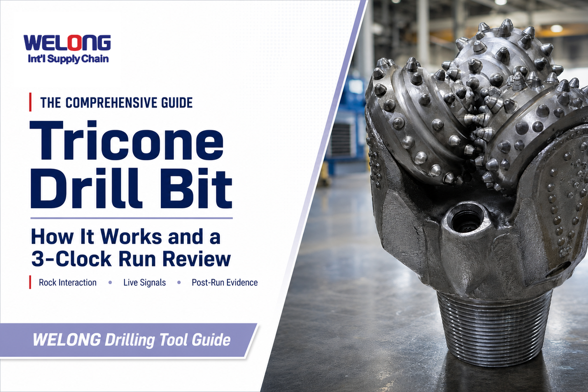
A Tricone Drill Bit is a rotary rock-cutting tool that breaks formation with three cones rotating on their own journals while the full bit turns at bottomhole. That familiar description is accurate, but it isn’t enough to explain a changing drilling response. Cutting structure, cone motion, bearings, hydraulics, and formation all leave clues that have to be read together.
Direct answer
A tricone bit uses three rotating cones to crush, gouge, and chip rock. During a run, changes in penetration, torque, vibration, current, or hydraulics are diagnostic signals, not proof of one failure. Pulled-bit condition and the drilling record must agree.
What matters most
- Dull-looking cutters are only one part of the story; cone rotation and cleaning can become the limiting systems.
- Changes at a formation boundary shouldn’t be diagnosed the same way as deterioration in a stable interval.
- Vibration and motor-current research can guide investigation, but it doesn’t provide one universal field threshold.
- Useful next-bit discussions start with a time- and depth-aligned evidence packet, not a verdict that the bit was simply “good” or “bad.”
How Does a Tricone Drill Bit Break Rock?
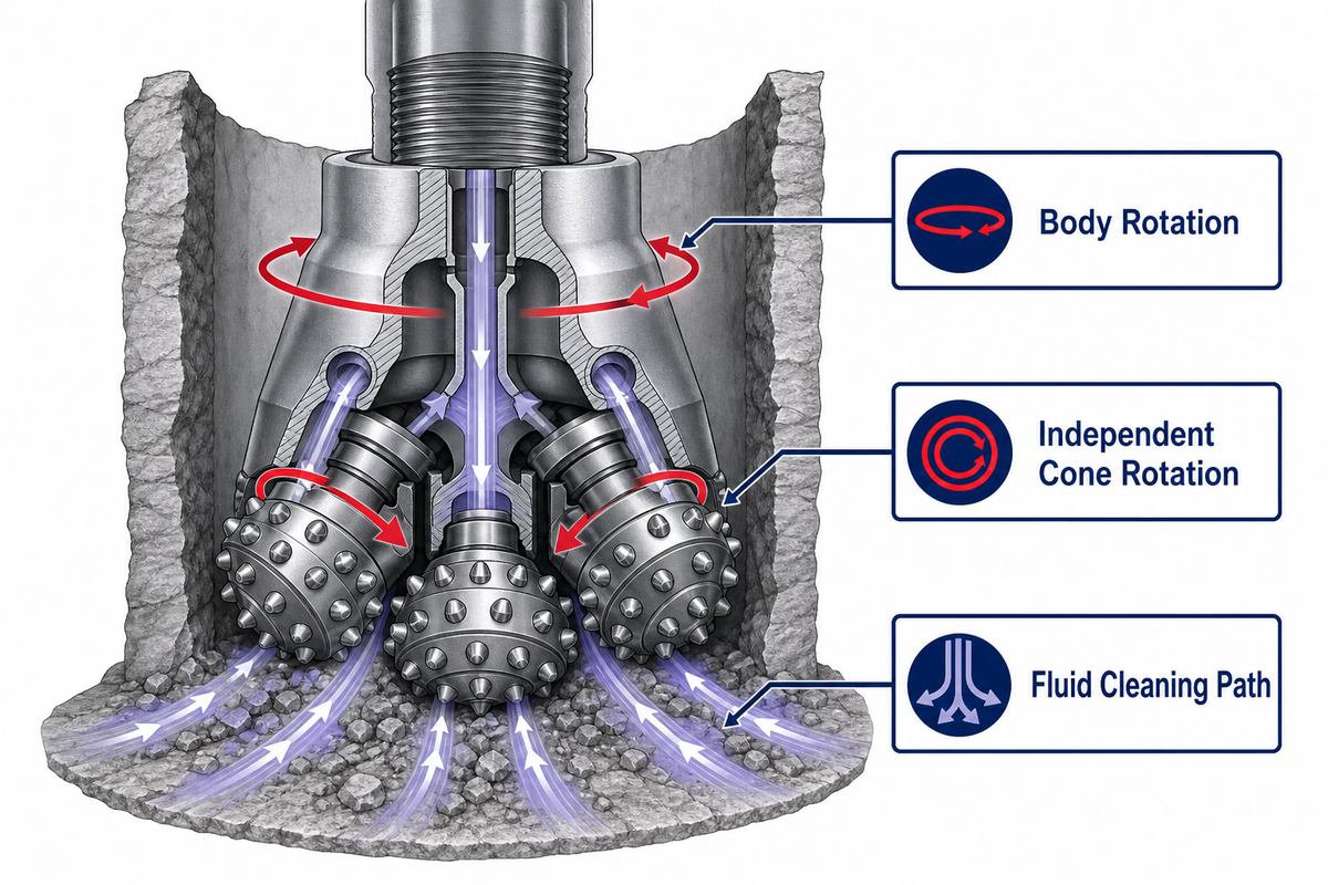
Tricone drilling combines two motions: the body revolves with the drill string, while each cone rotates around its journal. Rotation reaches the bit through the drill string and drill pipe. Teeth or inserts repeatedly enter and leave contact with the bottom, producing a changing mix of gouging, crushing, and chipping rather than one continuous scraping action.
Those two motions matter for different reasons. The rotation of the drill body supplies the overall movement, but cone geometry determines how the cutting structure meets fresh rock. Journal angle, cone shape, offset, and the cone axis alter the rolling path and the balance of rock-failure mechanisms. An SLB technical overview of drill bits describes journals as the axle-like structures around which the cones turn and explains how these design variables control the roll.
“Most roller cone bits have three metal cones that rotate independently as the bit turns on bottom.”
For historical context, Baker Hughes dates its two-cone launch to 1909 and the tricone introduction 24 years later. That timeline explains how the three-cone form emerged, but it does not replace a current application review.
That is why “three cones” should be treated as the start of the explanation, not the conclusion. Changes in tooth engagement can alter penetration. Restricted cone motion can change torque and vibration. Poor bottom-hole cleaning can make capable cutters recut or grind debris instead of penetrating fresh formation. Surface response is the combined result.
Key takeaway
Tricone performance comes from the interaction of cutting, rolling, and cleaning. Diagnoses that watch only one of those actions are incomplete.
Five Systems Shape the Drilling Response
Five connected systems shape what the driller sees at surface: the cutting structure, cones and journals, bearings and seals, nozzle hydraulics, and the outer structure that maintains hole condition. Separating them helps a team form testable causes instead of blaming every loss of performance on dull teeth.
| System | What it does | What a change may look like | What else can mimic it |
|---|---|---|---|
| Cutting structure | Engages and fails the rock | Progressive penetration loss or less effective engagement | Stronger or more abrasive formation |
| Cones and journals | Create the intended rolling contact | Irregular torque, vibration, or asymmetric wear | Interbedded rock or operating-input changes |
| Bearings and seals | Support cone rotation and retain the intended bearing environment | Restricted cone movement or heat-related evidence after pulling | Packed debris or physical handling damage |
| Nozzles and hydraulics | Clean and cool the bit while moving cuttings | Re-cutting, balling, pressure change, or slower cleaning response | Mud-property, flow, or returns changes elsewhere in the system |
| Outer structure | Helps maintain the required hole condition | Outer wear or an undergauge observation after the run | Abrasive interval, reaming, or another hole-condition issue |
SLB notes that bearing life became a limiting factor as cutting structures grew more aggressive. That historical point still carries a useful diagnostic lesson: roller cones can carry serviceable cutters while another system controls bit life. Product terminology may distinguish open bearing bits from sealed bearing bits, but the review principle is the same: worn teeth do not prove that bearing condition caused the change. Reliability and durability have to be evaluated across the whole run.
Hydraulics deserve the same discipline. Nozzles direct drilling fluid at bottom, clean cones and cutters, cool the steel, and help transport cuttings through the wellbore. If cleaning changes, the drilling response can deteriorate even though the teeth or inserts have not suddenly failed. Check the fluid side before assigning a mechanical cause.
Application context changes the cleaning system. A U.S. Office of Surface Mining training module on blasthole drilling, for example, describes compressed air keeping roller-cone bearings clean and cool. That is a useful mechanism example, not a universal fluid rule for every rig.
Milled Tooth vs TCI: Compare the Rock Interaction
Milled-tooth cones carry steel teeth formed as part of the cone, while TCI cones use tungsten carbide inserts pressed into prepared holes. Useful comparison starts with rock interaction, not “basic versus premium.” Review how each cutting structure engages the expected rock and what evidence its wear pattern can provide after a run.
Steel tooth bits are often discussed for softer formations and formations like shale; TCI bits are often considered as hardness rises or rock formations become hard and abrasive, including granite. These are starting points, not selection rules. A choice between teeth or tungsten carbide inserts still requires whole-system evidence; terms such as aggressive teeth or durable tungsten carbide inserts describe attributes, not suitability in hard formations.
| Question | Milled tooth | Tungsten carbide insert (TCI) | Do not conclude until you check |
|---|---|---|---|
| How is the structure made? | Steel teeth are formed on the cone and may carry wear-resistant material on exposed areas. | Separate carbide inserts are pressed into the cone. | Confirm the actual bit and cutting structure, not only the job record label. |
| How does it tend to engage rock? | Longer, sharper engagement can gouge and scrape lower-strength material. | Shorter or blunter inserts can chip and crush stronger rock. | Formation variability can change the dominant mechanism within one run. |
| What should inspection record? | Tooth wear, breakage, erosion, asymmetry, and material packing. | Insert wear, breakage, loss, asymmetry, and cone-body damage. | Depth, drilling response, and operating changes associated with the observation. |
| What is the boundary of this table? | It does not choose a tooth profile, bearing package, or IADC code. | It does not choose insert shape, density, or a product model. | Detailed application selection belongs in a bit-specific engineering review. |
For commercial configurations and application-specific bit choices, use the existing Tricone Drill Bit solution page. If you’re comparing the basic rock-removal mechanisms first, the tricone versus PDC decision guide keeps that comparison separate from this run-review method.
Live-Signal Diagnostic Matrix: A Signal Is Not a Verdict
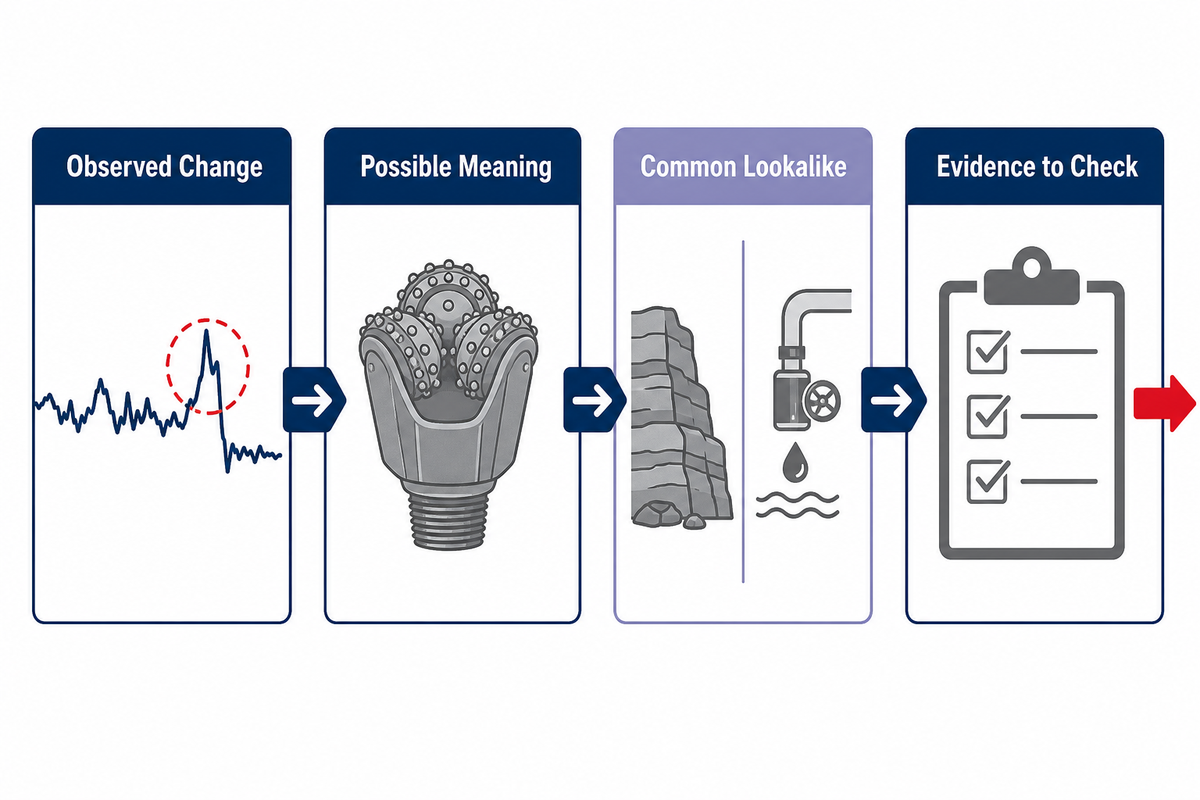
Live drilling signals are most useful for ranking what to check next. A falling rate of penetration (ROP), changing torque, unusual vibration, motor-current shift, hydraulic change, or an unexplained rotary speed change can be associated with bit condition, yet each can also be caused by formation, operating inputs, cleaning, or the wider drilling system.
Penetration rates from different drilling operations are not directly comparable without that context.
A 2021 peer-reviewed study in the International Journal of Mining Science and Technology investigated vibration and electric motor current in relation to tricone bit wear in full-scale mining operations. That supports the idea of signal-based condition monitoring. It doesn’t justify copying one threshold into every oilfield, mining, water-well, or HDD rig.
A Pacific Northwest National Laboratory conference study provides another application-specific example: real-time wear metrics from roller-cone insert runs in geothermal wells were interpreted alongside the actual dull grades after pulling. The general lesson is to pair trend evidence with post-run observation.
| Observed change | Possible bit-related meaning | A common lookalike | Evidence to check next |
|---|---|---|---|
| ROP falls gradually | Cutting structure may be losing effective engagement. | Formation strength or abrasivity increased. | Compare depth markers, WOB/RPM changes, and pulled-bit wear. |
| Torque rises or becomes erratic | Cone rotation may be restricted, or material may be packing around the bit. | Interbedded rock or a hole-condition change. | Check formation timing, returns, cone freedom, and asymmetry. |
| Vibration pattern changes | Wear or uneven cone behavior may have changed the contact pattern. | A lithology transition or operating-input change. | Align the signal with depth, parameters, and cone-by-cone inspection. |
| Motor current shifts | Mechanical demand may have changed with bit condition. | Drive load, speed, or formation changed. | Use a machine-specific baseline and correlate with other signals. |
| Pump pressure or returns change | Nozzle restriction or poor bottom cleaning may be reducing effective cutting. | A system-level fluid or annular condition changed. | Inspect nozzles and review fluid properties, flow, and returns. |
| Response changes at a boundary | The new formation may expose a bit limitation. | The formation change itself explains the response. | Look for persistence after the boundary and physical evidence after pulling. |
Do
- Align signals by time and depth.
- Record operating changes next to the response.
- Carry at least one competing explanation.
Don’t
- Call one spike a failure threshold.
- Ignore formation and hydraulics.
- Choose the next bit from surface data alone.
The 3-Clock Run Review
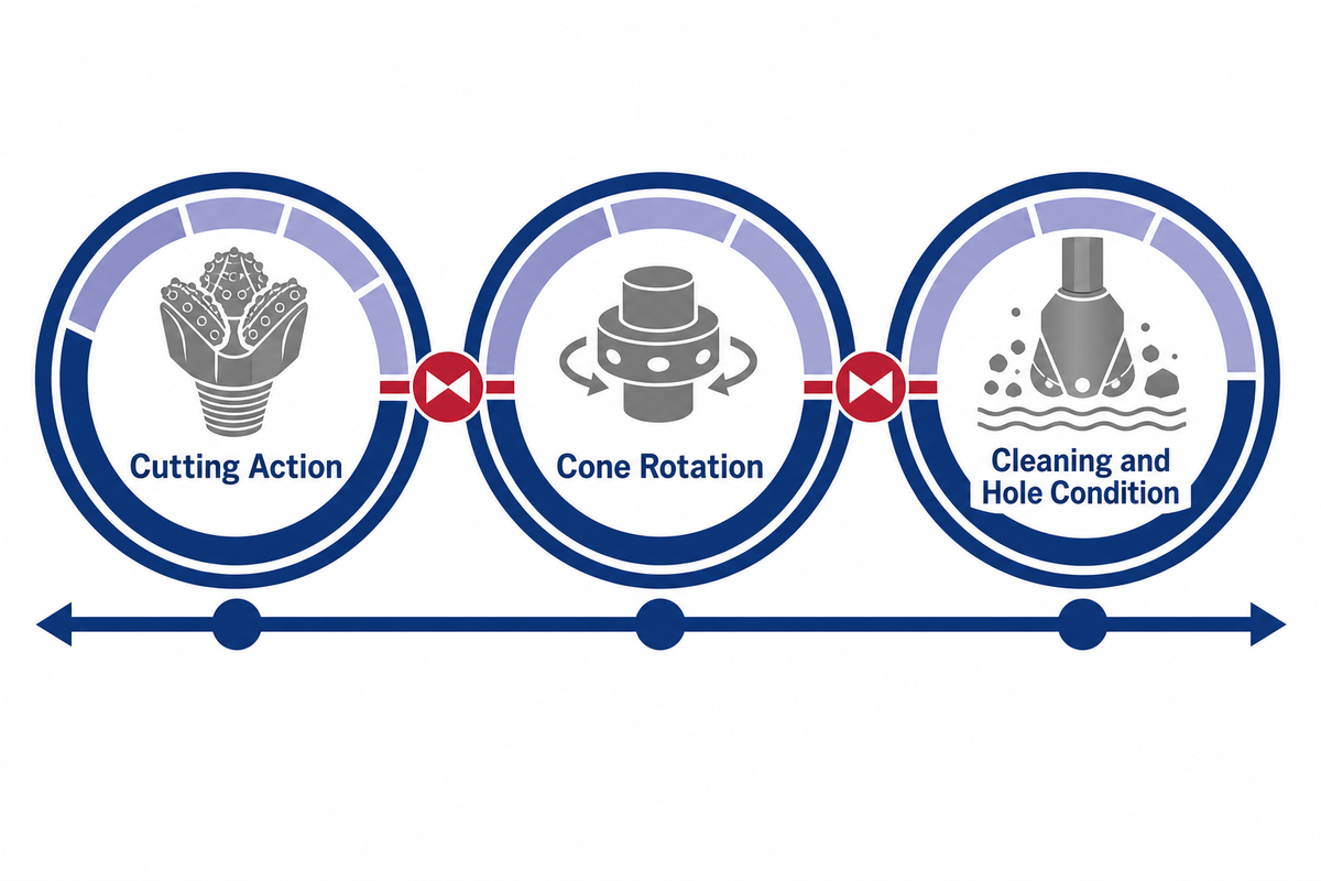
Our 3-Clock Run Review compares cutting action, cone rotation, and cleaning or hole-condition evidence on one timeline. One clock creates a hypothesis. Two clocks that agree make it stronger. Conflicting clocks tell the reviewer to test formation, hydraulics, or operating changes before blaming the bit.
Clock A · Cutting action
Track penetration response and energy demand, then compare them with tooth or insert condition after the pull.
Clock B · Cone rotation
Review torque or vibration changes alongside cone freedom, asymmetry, and bearing- or seal-related observations.
Clock C · Cleaning and hole condition
Compare hydraulic behavior, nozzle condition, material packing, and outer wear with the drilling timeline.
How should the three clocks change a decision?
Suppose ROP declines through an interval, but torque remains orderly and the pulled bit shows uniformly worn cutting elements with free cone rotation. Evidence then favors progressive cutting wear or formation abrasivity over a sudden bearing event. If ROP falls while torque becomes irregular and one cone resists movement after cleaning, the cone-rotation clock changes the priority of the diagnosis.
Now take the opposite case: penetration drops, surface pressure and returns change, and packed material surrounds otherwise serviceable teeth. Cleaning evidence demands attention. None of these examples supplies a universal operating rule; each shows how agreement across evidence changes the strength of a conclusion.
Formation-to-Observation Map: Keep a Competing Cause
Formation context decides how much weight to give a drilling-response change. Shifts in softer, sticky, hard, interbedded, or abrasive intervals may resemble bit wear for different reasons. Reviewers should pair every likely cause with an alternative and one observation that can separate them.
| Context | Response worth noting | Physical observation to seek | Competing cause | Next evidence |
|---|---|---|---|---|
| Soft or sticky interval | ROP or torque changes with cleaning behavior | Packed material, nozzle condition, cutting edges beneath deposits | Cutting wear | Returns, fluid changes, and condition after proper cleaning |
| Hard competent interval | Lower penetration or increased energy demand | Chipping, breakage, uniform insert wear, cone-body damage | Expected formation response | Persistence after the interval and comparison with offset response |
| Interbedded transition | Repeated torque or vibration changes | Asymmetric cutting wear or impact damage | Normal lithology alternation | Depth-aligned recurrence and operating inputs at each boundary |
| Abrasive interval | Gradual decline rather than one abrupt event | Progressive outer and cutting-structure wear | Hydraulic deterioration | Nozzle condition and wear progression by run segment |
| Apparently stable interval | Response deteriorates without a recorded formation or input change | Cutting, cone, bearing, nozzle, and outer-condition evidence | An unrecorded operating or geological change | Validate the log and compare all three clocks |
The hidden bottleneck is feedback quality. Bit price and nominal type are visible, but weak run records make the next decision non-repeatable. A useful review replaces “the bit stopped performing” with a ranked cause list: what was observed, which alternative still fits, and what the next run should test.
Post-Run Inspection: Separate Observation from Cause
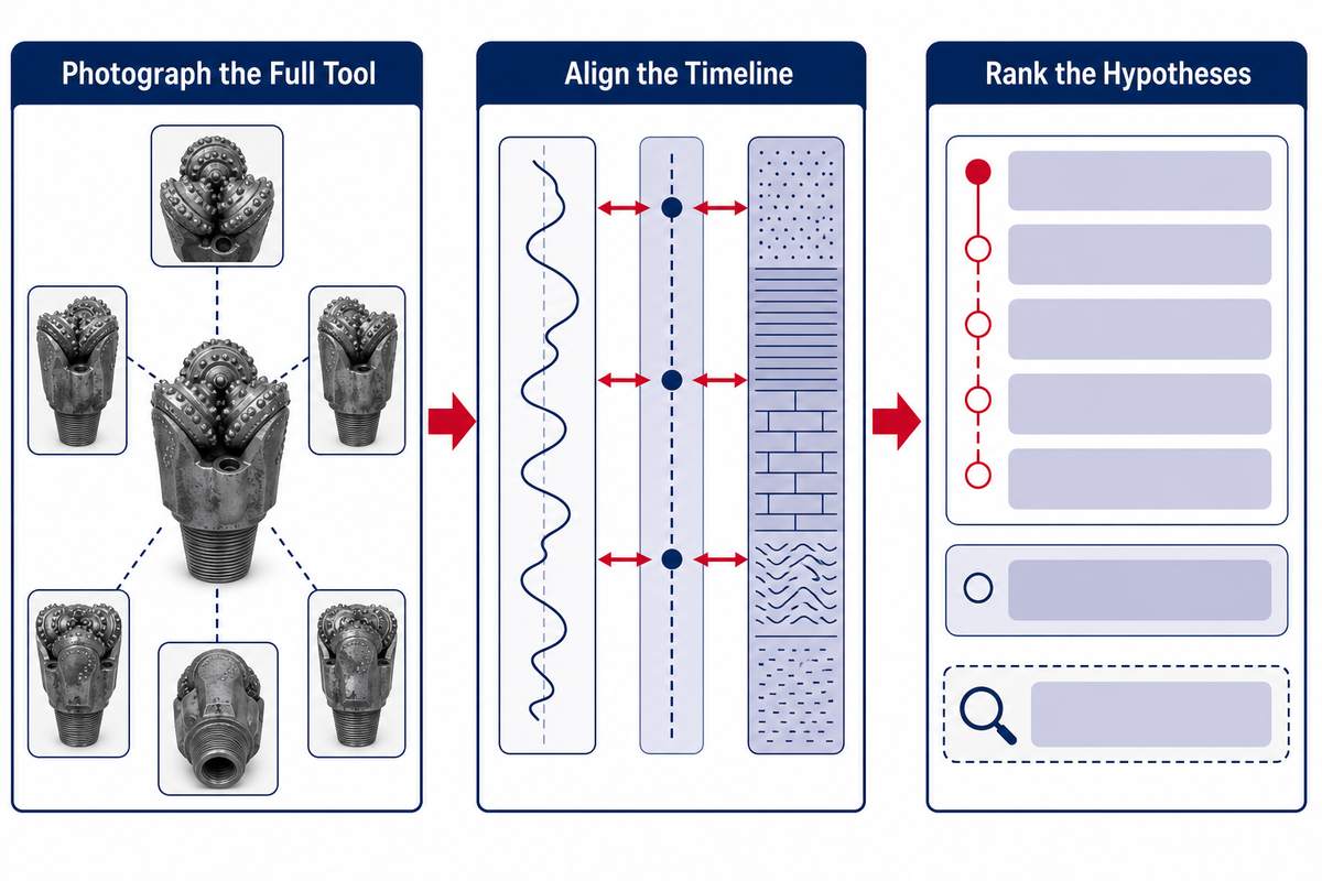
Post-run inspection should preserve facts before interpretation. Clean and orient the bit, photograph each cone, record cutting elements and cone movement, check nozzles and outer condition, then align those observations with the drilling timeline. Cause belongs in a separate field until the evidence supports it.
- Clean and orient the bit — use the same reference view so later comparisons are meaningful.
- Photograph the full tool — capture overall, cone-by-cone, nozzle, and outer-condition views before parts are moved or handled again.
- Record cutting-structure facts — note wear, breakage, loss, packing, erosion, and asymmetry without assigning a cause.
- Check cone behavior — document freedom of movement and any unequal behavior after proper cleaning.
- Review hydraulics evidence — inspect nozzles and material accumulation, then compare them with pressure and returns observations.
- Align the timeline — connect each surface change to time, depth, formation, and operating inputs.
- Rank the hypotheses — state the leading cause, the strongest alternative, and the next evidence that would separate them.
Consistent grading can improve that record. If your team uses IADC terminology, record what was actually observed and use a trained process or the site’s IADC code decoder as a reference aid. Don’t invent a formal grade from a partial photograph or an uncleaned bit.
This workflow also explains when a broader system check is needed. If the bit evidence and surface response do not agree, review the downhole drilling tools guide and the surrounding assembly rather than forcing a bit-only explanation.
The Nine-Field Handoff Sheet
Useful handoffs give the rig team, drilling engineer, and procurement or tool coordinator the same evidence in the same order. Nine fields are enough to preserve the run without turning the report into a diary: identity, interval, formation, inputs, response, hydraulics, physical condition, hypotheses, and next test.
| Field | What to record | Primary owner | Why the next decision needs it |
|---|---|---|---|
| 1. Bit identity | Traceable tool and configuration record | Tool coordinator | Prevents comparison of unlike tools |
| 2. Run interval | Start/end depth and time | Rig team | Creates the timeline anchor |
| 3. Formation sequence | Known intervals and transitions | Drilling engineer | Separates geology from tool condition |
| 4. Operating inputs | WOB, RPM, flow, and intentional changes where recorded | Rig team | Shows whether the response followed an input |
| 5. Drilling response | ROP, torque, vibration, and current trends where available | Rig team | Builds the three-clock record |
| 6. Hydraulic observations | Pressure, returns, fluid, and cleaning changes | Rig team | Tests the cleaning hypothesis |
| 7. Physical condition | Cutters, cones, nozzles, outer condition, photos | Rig team and engineer | Links surface data to the pulled tool |
| 8. Ranked hypotheses | Leading cause and strongest alternative | Drilling engineer | Keeps uncertainty visible |
| 9. Next test | One change or measurement that can separate causes | Engineer and tool coordinator | Turns the review into learning |
Procurement conversations also improve when this sheet travels with the tool. Coordinators can compare the actual application and disposition rather than evaluating only purchase price, cost per foot, or a nominal IADC label. That’s a better starting point for a technical discussion about the next drill bit application.
Bring Evidence to the Next Bit Decision
Start the next bit decision after the run record is aligned, not before. Bring the application, formation sequence, operating changes, three-clock observations, pulled-bit photos, and ranked hypotheses. Across drilling projects, those facts make a configuration or quotation discussion specific without turning an educational review into a sales claim.
China Welong’s public product pages can support the commercial step once that context is ready. Readers who need a comparison with a shearing cutter can review the PDC drill bit page. Readers who already know the application can take the evidence packet into a tricone configuration discussion.
Discuss the application with a cleaner evidence packet
Share the formation context, run signals, pulled-bit observations, and the next test you want the bit program to answer.
Frequently Asked Questions
What is a tricone drill bit used for?
A tricone drill bit is used to drill rock in oil and gas, mining, water-well, geothermal, horizontal directional, and other rotary drilling applications. Its rolling cones and steel teeth or carbide inserts provide versatility across varied formations, but the application name alone does not select the bit. Formation sequence, hole size, rig capability, hydraulics, and the run objective still require engineering review.
Use the application as context, then match the full drilling system and expected rock interaction. Two wells or benches carrying the same application label may still present different strength, abrasivity, transitions, cleaning requirements, and rig limits. Those details determine whether the cutting structure, bearing arrangement, and hydraulic package fit the job.
How does a tricone drill bit work?
The bit body turns with the drill string while three cones rotate independently on journals. Steel teeth or carbide inserts enter and leave contact with the bottom, producing a mix of gouging, crushing, and chipping. Fluid jets clean and cool the cutting area and help move broken material away so the cutters can reach fresh rock.
Cone geometry and hydraulics therefore matter alongside the cutting structure. Journal angle, cone shape, and offset influence the rolling path, while nozzle placement influences cleaning at the contact zone. Surface penetration and torque reflect these systems together, so a change should be correlated with formation, operating inputs, and pulled-bit condition.
What is the difference between milled-tooth and TCI tricone bits?
Milled-tooth bits use steel teeth formed on the cones, while TCI bits use separate tungsten carbide inserts pressed into the cones. Their geometry and materials support different rock-engagement and wear behaviors. Selection still depends on the full design and application, including formation variability, bearing system, hydraulics, rig limits, and the planned operating window.
Compare how the structures interact with rock before comparing product families. Longer steel teeth can provide a different engagement pattern from shorter carbide inserts, but either description is incomplete without the intended formation. After a run, record wear, breakage, loss, packing, asymmetry, and cone condition rather than judging only the material name.
What causes a tricone bit to stop drilling efficiently?
Efficiency can fall because of cutting-structure wear, restricted cone motion, bearing or seal problems, poor cleaning, material packing, outer wear, formation change, or operating conditions that no longer fit the bit.
The three-clock review helps separate these possibilities instead of treating one surface signal as the answer.
Can torque or vibration alone prove that a tricone bit is worn?
No. Torque and vibration can help detect a change, but formation transitions, operating inputs, hole condition, and hydraulics can create similar responses. Treat the signal as a reason to check more evidence.
A stronger conclusion comes from agreement between the drilling timeline and the pulled-bit inspection.
What should be recorded after pulling a tricone bit?
Record bit identity, run interval, formation changes, operating inputs, ROP and torque trends, vibration or current where available, hydraulic observations, cutting and cone condition, nozzles, outer wear, photos, hypotheses, and the next test.
Keep observed facts separate from inferred causes so another reviewer can reach an independent conclusion.
References & Sources
- The Defining Series: Bits SLB Oilfield Review
- Drilling signals analysis for tricone bit condition monitoring International Journal of Mining Science and Technology, 2021
- Tricone drill bits Baker Hughes
- Blasthole Drilling U.S. Office of Surface Mining Reclamation and Enforcement
- Optimizing Rate of Penetration and Tripping Decision-Making Using Real-Time Bit Wear Monitoring Pacific Northwest National Laboratory
Editorial scope: This guide is based on public technical sources and general diagnostic reasoning. It doesn’t replace formation-specific bit selection, a trained dull-grade inspection, or the operating procedures for a particular rig.
![Choke & Kill Hose: [Field Guide]](https://welongoiltools.com/wp-content/uploads/2026/07/choke-kill-hose-guide-featured-1-150x150.png)