Get in touch with Welong Company


Updated August 2026 · Engineering guide for drilling, inspection, and procurement teams
A Drilling Stabilizer is a gauge-contact component in the bottom hole assembly (BHA). Its blades provide discrete lateral support against the borehole wall, changing how the drill collars bend and how side force reaches the bit. In oil and gas drilling, that contact path can affect drilling performance, but it cannot correct every bit, formation, hydraulics, hole-cleaning, or wellbore-geometry problem.
Drilling stabilizers change where the BHA is laterally supported. Resulting behavior depends on gauge and position plus the bit, drill collars, hole shape, formation, WOB, RPM, and fluid system. Evaluate with measurements, not one signal.
Key points before you change the BHA
- One stronger vibration or torque signal does not, by itself, prove stabilizer wear.
- Near-bit and string describe placement roles; integral, welded, and replaceable-sleeve describe construction.
- No public evidence reviewed for this guide supports one universal spacing or gauge-loss rejection limit.
- Useful handoff evidence comes as a matched packet: BHA layout, run context, measurements, inspection evidence, and the authority behind the final disposition.
Across modern drilling operations, different types of drilling place different demands on stability and control. Directional drilling and horizontal drilling may magnify dogleg, contact, and hole-cleaning questions across geological formations, but the same evidence rule applies to the drilling process.
In this guide
What a Drilling Stabilizer Does—and Does Not Do
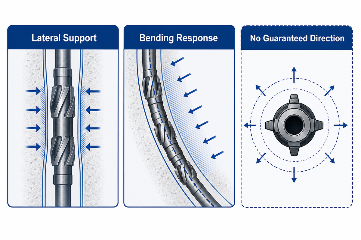
Stabilizer blades support the drill string laterally where they approach or touch the borehole wall. Contact at that point changes drill-collar bending, bit side force, and the assembly’s response to rotation and load. This component influences a system; it does not independently guarantee hole direction, low vibration, or trouble-free drilling.
Picture a long beam with several supports. Move one support, change its clearance, or remove effective contact through wear, and the beam can bend differently. In a BHA, that change may alter bit tilt, local side force, natural frequencies, and where the string rubs the hole. Yet the response still belongs to the complete assembly and wellbore.
SSRN hosts a BHA placement paper that explains classical fulcrum, packed-hole, and pendulum arrangements. Its spacing examples are useful teaching context, not a design standard. Its discussion points to variables such as hole and collar size, inclination, stabilizer gauge, WOB, rotary speed, and formation response.
What is the use of a stabilizer in drilling?
Stabilizers create controlled lateral support in the BHA so engineers can shape directional tendency and manage how the drill string responds to bending and rotation. More predictable contact behavior is the useful outcome—not immunity from formation effects, bit dysfunction, or hole-quality problems.
Three effects deserve attention: where the assembly contacts the borehole, how that geometry changes directional tendency, and whether the vibration pattern changes across a run. Those effects should be compared with the other downhole drilling tools and the bit, motor or rotary-steerable system in the same BHA.
Stabilizers can influence
- Lateral support and contact location
- Bit side-force tendency
- Drill-collar bending response
- Some vibration modes
Stabilizers cannot prove
- Root cause from one surface signal
- Guaranteed build, hold, or drop rate
- Universal safe RPM or WOB
- That hole cleaning or the bit is operating normally
How Gauge Contact Changes the Drill String and BHA
Gauge contact changes the boundary conditions of the bottom hole assembly. Each load-carrying blade adds local support; clearance or wear reduces that support and permits more flexure before contact. Observable results may be directional, vibrational, or frictional, but each one requires a separate check before assigning cause.
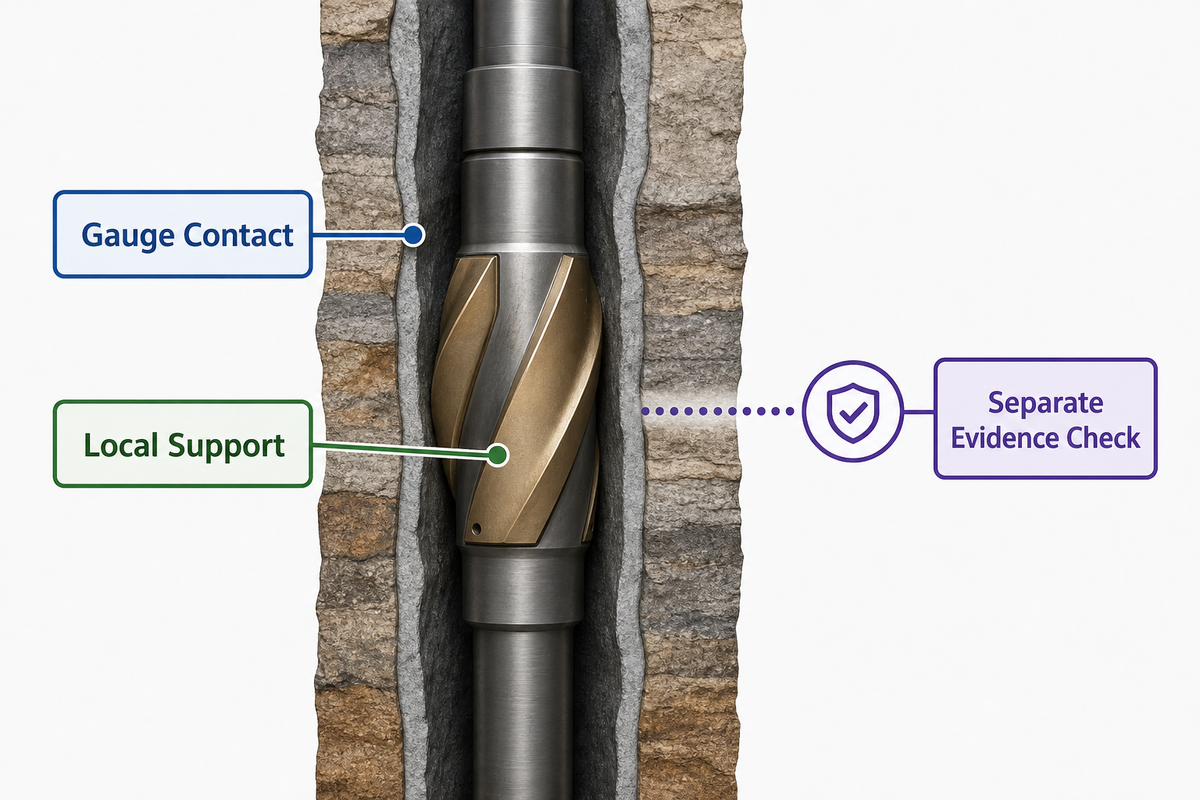
“Full gauge” is not a promise that every blade carries equal load. An enlarged, washed-out, oval, or ledged borehole can remove contact on one side and concentrate it elsewhere. In a curved section, gravity and wellbore geometry also shift the contact path. Even a dimensionally correct tool may work under changing constraints from one interval to the next.
Changes can travel from the drill bit and stabilizer through drill collars to drill pipe, so string vibration and directional control cannot be read from one contact mark. Use a depth-matched dogleg response and the as-run drilling path beside the physical inspection.
University of Texas research likewise used BHA strain energy and stabilizer side force as vibration-design indices. It supports the engineering logic that contact layout belongs in the model. It does not support attributing field vibration to the stabilizer from appearance alone. Read the university repository record as modeling evidence.
| Input | Contact change | Possible observation | Verification |
|---|---|---|---|
| Gauge loss | More clearance before blade contact | Changed bending or directional tendency | OD by blade and position, BHA model, survey response |
| Tight or undergauge hole | More frequent or higher local contact | Torque, drag, or contact marks | Caliper/hole evidence, trip behavior, blade pattern |
| Washout or ovality | Intermittent or asymmetric support | Variable trajectory or lateral response | Hole geometry, depth correlation, circumferential wear |
| Placement change | Different unsupported collar length | Different side-force or vibration tendency | As-run BHA drawing, model assumptions, downhole data |
| Formation change | Contact may be unchanged | Similar torque, vibration, or trajectory signal | Lithology, bit dull, hydraulics, adjacent-run comparison |
String Stabilizer and Near-Bit Placement Without a Universal Recipe
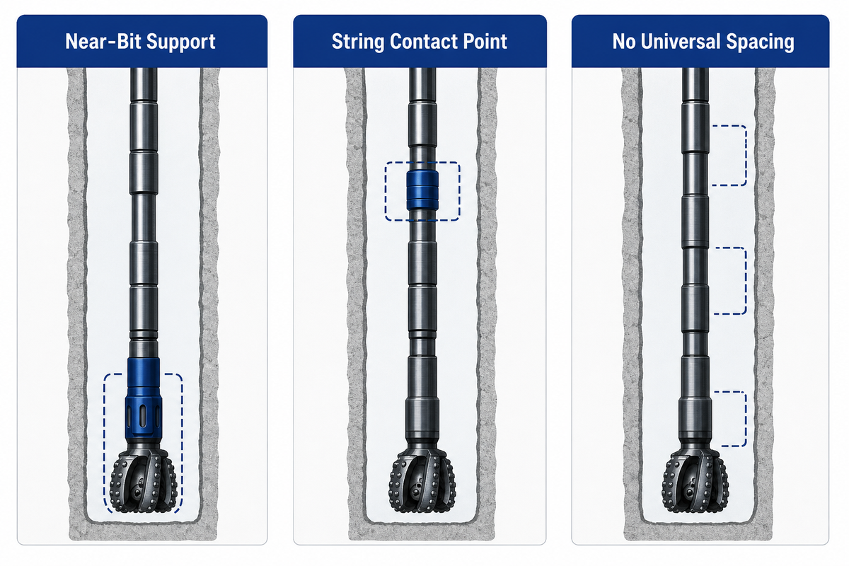
Near-bit stabilizers support the assembly close to the bit, while string stabilizers add a contact point higher in the drill-collar section. Their spacing changes bending length and side-force tendency. Well objectives and the BHA model should determine the layout; a copied distance ignores the variables that create the response.
Classical names describe the intended geometry. Fulcrum arrangements use near-bit support to help create a building tendency. Engineers use packed-hole arrangements with closely placed supports to resist bending and tend toward holding angle. Pendulum arrangements leave more unsupported collar below an upper contact point so gravity can contribute to a dropping tendency. Each is a tendency, not a guaranteed steering command.
Modern drilling assemblies may also include motors, measurement packages, rotary-steerable systems, reamers, and other contact elements. Those components change stiffness, sensor spacing, mass distribution, flow area, and contact. Any placement rule detached from the actual assembly is therefore incomplete even when the textbook label is correct.
Specific drilling conditions should drive stabilizer designs: target drilling path, drilling requirements, component limits, wellbore geometry, and available model evidence. Catalog labels cannot substitute for those inputs.
Why is there no single correct stabilizer spacing?
There is no single correct spacing because the same distance does not produce the same bending or side force in different holes and BHAs. Hole diameter, collar stiffness, inclination, stabilizer gauge, WOB, RPM, formation, curvature, washout, bit response, and other tools all change the boundary conditions.
Write the objective first: build, hold, drop, reduce a modeled vibration mode, protect a sensitive component, or improve contact control. Then document the variables used in the model. Commercial selection starts only after that engineering definition; the drilling stabilizer models and sizing options page owns model-fit and sourcing decisions.
Integral Blade Stabilizers, Welded Blade and Replaceable Sleeve Terms
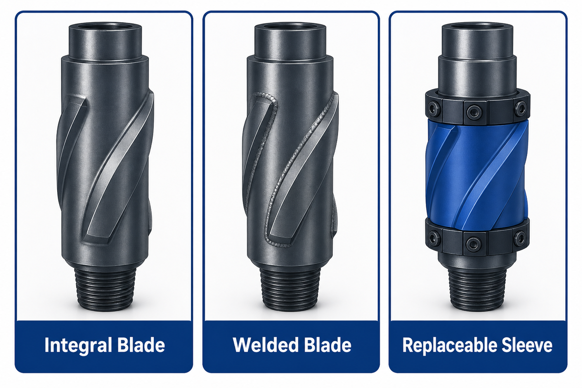
Integral blade, welded blade, and replaceable sleeve describe how a stabilizer is built. Near-bit and string describe where it sits. Roller reamer, underreamer, centralizer, drill collar, and stabilizer describe different tool functions. Separating those label families prevents a placement request from turning into the wrong product specification.
Integral blade stabilizers are machined as single-piece bodies with stabilizing blades formed from the body. Welded blade stabilizers add blades by weld to a tubular body, which makes weld procedure and heat-affected-zone evidence relevant. Designers use the exact term “replaceable sleeve stabilizer” for a design that separates the bladed sleeve from the mandrel, shifting part of the maintenance and fit discussion to the sleeve/mandrel interface.
These functional descriptions do not rank one construction as universally better. Loading, repair philosophy, traceability, magnetic suitability, connection design, wear mechanism, and service provider criteria decide the trade. For the narrow construction decision, use China Welong’s integral blade or replaceable sleeve comparison rather than reproducing its selector here.
| Type or label | What it describes | Useful specification question | Limitations / not the same as |
|---|---|---|---|
| Integral blade | Single-piece body and blade construction | Material route, thermal processing, hardfacing, repair criteria | Does not define near-bit or string position |
| Welded blade | Blades welded to the stabilizer body | WPS/PQR, HAZ control, inspection and repair route | Weld quality cannot be inferred from the label |
| Replaceable sleeve | Bladed sleeve fitted to a mandrel | Interface, retention, compatibility and sleeve traceability | Replaceable does not mean field acceptance is automatic |
| Near-bit stabilizer | Placement close to the drill bit | Objective, connection stack and bit-to-contact distance | Position role, not one manufacturing form |
| String stabilizer | Placement higher in the collar string | Unsupported lengths and system contact points | Position role, not a material grade |
| Packed-hole arrangement | Closely supported BHA tendency | What hold tendency and hole conditions are modeled? | Not a fixed spacing formula |
| Fulcrum arrangement | Near-bit support used for building tendency | What creates the predicted bit side force? | Not a guaranteed build rate |
| Pendulum arrangement | Unsupported lower collar used for dropping tendency | How do inclination, WOB, hole shape and collar stiffness enter? | Not a guaranteed drop rate |
| Roller reamer / underreamer | Rolling gauge contact or active hole enlargement | Is the job stabilizing, reaming to gauge, or enlarging? | Adjacent categories, not synonyms for a fixed-blade stabilizer |
Hidden Bottleneck Map—Stabilizer Contact or a Look-Alike Cause?
Use the Hidden Bottleneck Map to keep a field observation from becoming a premature root cause. It pairs each signal with a plausible stabilizer-contact path, common look-alike causes, and the next evidence to collect. Change the stabilizer only when measurement, inspection, modeling, or run context supports the contact hypothesis.
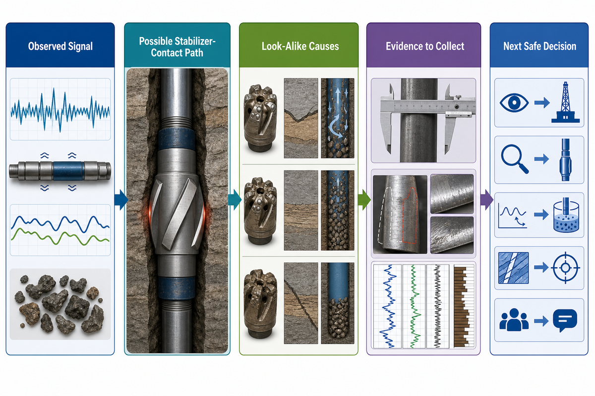
This map is intentionally asymmetric: many paths can produce a torque, vibration, or trajectory change, but fewer can prove which path operated. This is why “the stabilizer caused it” is usually weaker than “the as-run gauge and contact pattern, together with the BHA model and depth-matched response, support it.”
2-Evidence Rule for a Stabilizer Decision
Start with the observed signal as the first evidence stream. Seek an independent second stream: a mapped measurement, a post-run inspection pattern, a BHA model using actual dimensions, or a depth-matched comparison with bit, formation, hydraulics, and parameters. If the two streams disagree, keep the cause open.
Published in 2024, a University of Baghdad review of stuck-pipe mechanisms groups warning signals with wellbore instability, differential sticking, improper hole cleaning, cuttings beds, and other drilling conditions. That evidence keeps torque/drag from being attributed only to the stabilizer. Read the peer-reviewed stuck-pipe review for the broader mechanism boundary.
| Observed signal | Possible stabilizer-contact path | Look-alike causes | Evidence to collect | Next safe decision / limitation |
|---|---|---|---|---|
| Unexpected build/drop tendency | Gauge loss or changed effective contact point | Formation dip, bit walk, WOB/RPM change, motor setting | As-run gauge, BHA model, survey-by-depth, bit dull | Change layout only after the model with actual gauge matches the trend |
| Lateral vibration rises | Lost support or a new contact node | Bit whirl, resonance, washout, motor or RSS behavior | Downhole vibration, RPM sweep, hole geometry, inspection pattern | Surface signal alone is insufficient |
| Torsional vibration / stick-slip | Contact friction contributes to loading | Bit-rock interaction, motor, RPM/WOB, formation transition | Downhole torsional data, bit condition, parameter timeline | Do not infer blade wear from stick-slip alone |
| Torque/drag increases | More contact, tight clearance, or asymmetric rubbing | Cuttings bed, swelling formation, keyseat, differential sticking | Depth correlation, cleaning indicators, overpull/rotation response, caliper evidence | Treat as a multi-cause warning, not a component verdict |
| Repeated gauge loss | High local contact or unsuitable wear system | Abrasive solids, washout, BHA bending, measurement inconsistency | Circumferential OD map, fluid/formation record, instrument and datum | Compare pattern and environment before changing hardfacing |
| Localized blade spalling | Impact or concentrated contact at a blade zone | Deposition defect, thermal damage, debris, mishandling | Macro photos, NDT, hardface map, run and handling history | Disposition follows the documented repair/acceptance authority |
| Recurring contact marks | Persistent wall contact at the same clocking zone | Hole ovality, BHA eccentricity, connection misalignment | Blade clocking photos, straightness, connection inspection, caliper log | Confirm whether the pattern follows the tool or the hole |
| Tight spot while tripping | Stabilizer clearance or damaged blade catches a restriction | Ledge, keyseat, cuttings pack, casing or connection issue | Depth repeatability, circulation response, overpull and rotation response | Use the stuck-pipe procedure; do not assume spontaneous blade failure |
| Connection fretting or shoulder damage | Contact load may raise bending at the connection | Make-up error, fatigue, misalignment, handling damage | Connection dimensions, MPI/UT as required, make-up and run records | Connection disposition is separate from blade gauge disposition |
Key takeaway
Treat an observation as a stabilizer decision only after a second evidence stream—measurement, inspection, modeling, or depth-matched run context—supports the contact path.
Gauge-Loss Field Check Sheet—What to Record Before Reuse
Use the gauge-loss check sheet to record what was measured, where it was measured, how it was measured, and which document controls final disposition. It keeps observation separate from acceptance. That separation lets inspection, drilling, and procurement discuss the same evidence without inventing a universal wear or reuse limit.
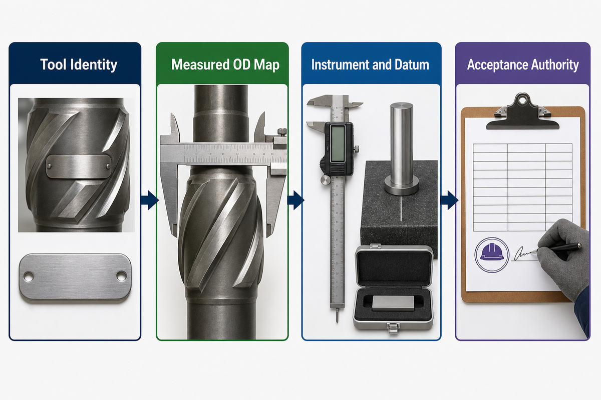
“Undergauge” is incomplete without a reference. The record needs the nominal gauge from the correct drawing or purchase specification, the actual OD at identified blades and axial positions, and the calculation method. It also needs the measurement instrument and datum so a later inspector can reproduce the result rather than compare incompatible readings.
Send the check sheet with tool identity and run context. Even a stable drilling decision can change if the inspected piece cannot be tied to its material certificate, thermal-process record, NDT record, dimensional report, repair history, or BHA position. China Welong describes those records as part of its first-party manufacturing and traceability process; buyers should request the records required by their own program and contract.
📐 Engineering note
Record the actual value and datum first. Apply an acceptance limit only after identifying the current operator procedure, manufacturer instruction, contract requirement, repair specification, and applicable standard revision.
| Record | What to enter | Why it matters | Acceptance authority |
|---|---|---|---|
| Tool identity | Serial/tool ID, drawing and revision | Prevents records from moving between tools | Traceability procedure / contract |
| BHA location | Near-bit/string role and as-run position | Connects wear to the actual contact layout | As-run BHA record |
| Nominal gauge | Value and source drawing/specification | Defines the reference for gauge loss | Controlled drawing / PO |
| Measured OD map | Each blade, multiple axial positions, units | Shows minimum, spread, and asymmetry | Inspection procedure |
| Gauge-loss calculation | Nominal minus measured, method stated | Makes the arithmetic reviewable | Inspection procedure |
| Instrument and datum | Gauge/micrometer ID, calibration status, datum | Supports repeatability and uncertainty review | Metrology procedure |
| Wear pattern | Uniform, tapered, localized or circumferential | Separates total loss from contact path | Inspector observation |
| Hardfacing condition | Polishing, binder loss, spalling, cracks, missing area | Guides mechanism and repair review | Manufacturer/repair specification |
| Body and blade condition | Dents, wash, deformation, weld/HAZ observations | Finds damage not represented by OD alone | Inspection and repair procedure |
| Connections and shoulders | Thread, seal face, shoulder, fretting, galling | Keeps connection integrity separate from blade gauge | Connection inspection criteria |
| NDT status | Method, procedure revision, date, result, technician | Connects visible wear with crack/damage screening | Applicable NDT procedure |
| Run context | Hole section, footage/hours if available, formation, events | Lets reviewers test a wear-mechanism hypothesis | Daily/run records |
| Photos | Full tool, each blade, scale, clocking and defect close-ups | Preserves the pattern for remote review | Inspection procedure |
| Disposition | Accept, repair, downgrade, retire, or engineering review—plus signer and document | Separates measured fact from authorized decision | Operator/manufacturer/contract authority |
Which records should travel with the stabilizer?
Each stabilizer record should carry tool identity, controlled dimensions, material and heat-treatment evidence, NDT and dimensional reports, repair history, connection information, as-run BHA position, run context, measured wear map, photographs, and the signed disposition. Missing lineage turns a precise number into an uncertain decision.
Do
- Map every blade and measurement position
- Name the instrument, datum, and procedure
- Keep photos tied to tool ID and clocking
- Name the authority behind the disposition
Don’t
- Record one OD as if wear were uniform
- Mix nominal values from different revisions
- Call appearance alone a wear mechanism
- Invent a site-wide acceptance limit
Hardfacing, Material and Non-Magnetic Specification Boundaries
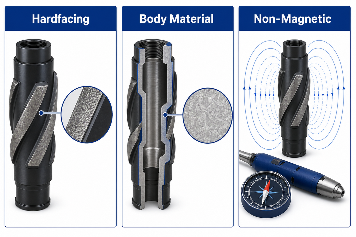
Material and hardfacing claims need separate proof for base metal, heat treatment, deposited layer, application process, magnetic behavior, and service environment. Laboratory results can explain a wear mechanism, but they cannot certify a vendor grade or predict field life without matching material, process, loading, fluid, and abrasive conditions.
AISI 4145H is widely associated with downhole drilling-tool steel, and a peer-reviewed 2022 study tested its wear in drilling-fluid abrasive environments. Results changed with abrasive hardness and the steel-to-abrasive relationship: soft abrasives favored polishing, while hard particles introduced microcutting and raised wear. Read the full AISI 4145H paper as laboratory evidence, not a stabilizer reuse limit.
Many conventional bodies are hollow cylindrical downhole tools made from heat-treated alloy steel or another high-strength steel. Wear-resistant hardfacing can improve wear resistance under a matching mechanism, but neither phrase proves field life, inspection acceptance, or equivalence between supplier grades.
Hardfacing is similarly conditional. A study of plasma-transferred-arc tungsten-carbide layers found that carbide morphology, quantity, binder/interfacial structure, and thermal history influenced wear in its specimens. The work also observed preferential wear in binder regions. Those findings explain why two hardfaces with the same broad “WC” label may behave differently; they do not map the China Welong hardfacing grade selector to the paper. Review the PTAW hardfacing study for its actual substrate and abrasion method.
Separate Ni-WC research on steel-body PDC bits found carbide toughness more influential than particle size under its high-stress abrasion regime, and it judged one abrasion method more representative than another for that bit application. This is a useful counterpoint to “larger carbide is always better.” It remains bit-specific test evidence, as stated in the peer-reviewed Ni-WC paper.
| Evidence | What it can support | What it cannot support |
|---|---|---|
| Material certificate | Identity and reported chemistry/properties for the supplied heat | Field life or hardface performance |
| Thermal-process record | Controlled process and traceability | Actual final properties without matching tests |
| Lab abrasion paper | Mechanism under named material and test conditions | Universal field wear rate or rejection threshold |
| Vendor grade name | Commercial selector within that vendor’s system | Equivalence to an academic composition without proof |
| Post-run inspection | Observed condition and measured loss | Root cause without run context and corroboration |
When is a non-magnetic stabilizer considered?
Consider a non-magnetic stabilizer when the survey and logging architecture requires magnetic-interference control near magnetometer-based MWD or LWD sensors. Required material, spacing, magnetic properties, inspection, and verification come from the project tool layout and provider criteria; non-magnetic is not a universal upgrade for every assembly.
Research published in 2024 by Sensors explains that metallic drilling equipment can distort magnetometer-based azimuth and that MWD packages are commonly placed in a non-magnetic collar environment. It also evaluates gyro-aided filtering, showing why the requirement belongs to the complete survey method. See the MWD magnetic-interference study. For a commercial screening step, use the non-magnetic stabilizer check after the survey-system requirement is defined.
What Is Changing in Stabilizer Verification?
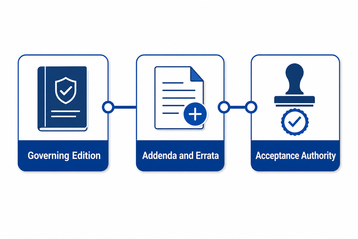
Document control—not a forecast slogan—is the practical change. API Spec 7-1 remains in its second edition, while later addenda and errata changed the current document set. Buyers should name the edition, addendum, errata, procedure revision, and acceptance authority in the inquiry and inspection packet.
API’s official notice says the second edition was published in 2023. API later issued Addendum 1 with an effective date of 3 September 2025, followed by Errata 2 issued in October 2025. Purchase orders that say only “API 7-1” can therefore leave document status unclear.
Public notices do not reproduce every paid clause and do not create an in-service gauge-loss limit. Procurement should confirm which sections apply to the requested tool, which inspection or repair document governs the used tool, and whether operator criteria add tighter conditions. Patent filings can show design direction, but a patent claim is not evidence that a design achieved a field result.
When a Stabilizer Cannot Fix the BHA
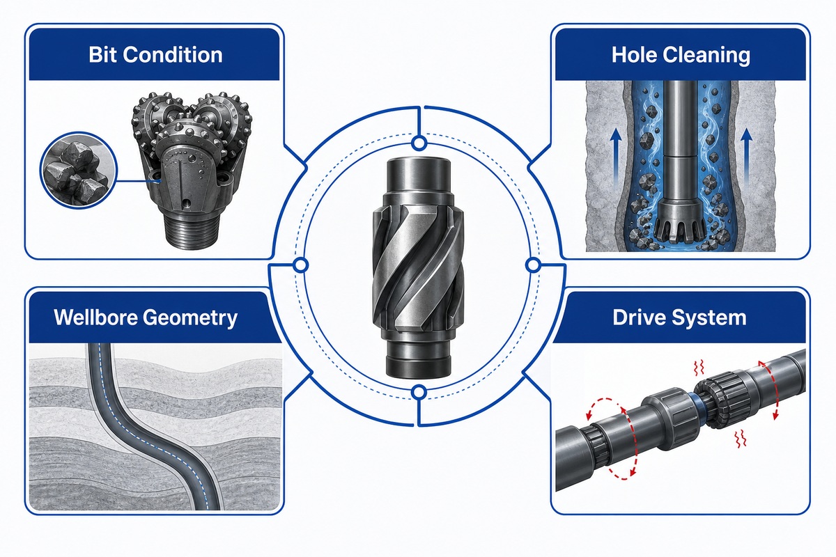
Stabilizers cannot fix a bit that is mismatched or damaged, a hole that is poorly cleaned, unstable formation, differential sticking, an unsuitable fluid system, a damaged connection, or operating parameters that excite the assembly. Check those paths before treating a different stabilizer as the single corrective action.
Ordered from context to hardware, the exclusion sequence protects the team from replacing a visible component while leaving the load-bearing cause untouched. It also works as a communication tool: the drilling superintendent can show which checks were completed, while inspection and procurement can see what evidence remains missing.
- Match the event to depth and time — align survey, vibration, torque/drag, pressure, ROP, WOB and RPM with formation and hole section.
- Check the bit and drive system — review dull condition, gauge, motor or RSS behavior and any parameter change.
- Test hole cleaning and wellbore geometry — review cuttings transport indicators, circulation response, caliper evidence, ledges, keyseats and washout.
- Reconstruct the as-run BHA — use actual component lengths, locations, gauges, connections and sensor spacing rather than the planned sketch alone.
- Inspect the stabilizer and connections — map OD, blade/hardface condition, body damage, shoulders, threads and required NDT.
- Model or compare the supported hypothesis — test actual worn gauge and placement against the observed response or a matched offset run.
- Authorize the disposition — apply the current operator, manufacturer, contract and procedure criteria; record the signer and revision.
If the evidence points to a different cause, changing stabilizer construction or gauge may add a new variable without removing the old one. If the evidence remains ambiguous, define what the next run must measure. “Insufficient evidence” is a sounder engineering state than a confident but unsupported part swap.
From a Field Finding to a Technical Inquiry
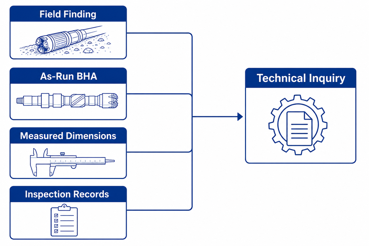
Good technical inquiries give engineering and procurement the same operating picture: hole section, objective, as-run BHA, bit and parameters, measured tool dimensions, wear photos, inspection and NDT records, connection, material and hardfacing needs, magnetic constraints, and the document that will control acceptance.
Start the request with the operational objective and the problem statement, not a catalog label. “Replaceable sleeve string stabilizer” still leaves unanswered why the contact is needed, what gauge and connection control it, where it sits, what magnetic environment applies, how wear will be measured, and what evidence must arrive with the tool.
Claims of drilling efficiency or cost-effective drilling need a named baseline, measured output, time window, and cost boundary. Without those inputs, keep the inquiry focused on the engineering requirement and the evidence packet.
For first-party manufacturing context, China Welong describes forging, thermal processing, machining, inspection, and traceability on its manufacturing and traceability page. Treat those as supplier statements to verify against the quotation, inspection and certification packet—not independent proof of field performance.
Prepare the evidence before selecting a model
Bring the BHA layout, objective, dimensions, connection, inspection record, photos, material/hardfacing boundary and magnetic requirement to the model-fit discussion.
Drilling Stabilizer FAQ
These short answers preserve the same evidence boundary as the main guide: a stabilizer changes BHA contact and support, while placement, wear, materials, vibration, and reuse decisions remain specific to the assembly, well, inspection program, and controlling documents.
Q: What is the purpose of a stabilizer in drilling?
Drilling stabilizers provide discrete lateral support in the BHA, influencing drill-collar bending, bit side force, directional tendency, and vibration response under specific drilling conditions in practice.
Drilling stabilizers provide discrete lateral support in the BHA, influencing drill-collar bending, bit side force, directional tendency, and vibration response. They form one part of the assembly: bit design, formation, hole geometry, WOB, RPM, hydraulics, motors or RSS, and other contact points still shape the result. Aim for a controlled contact condition, not a universal promise to drill straight or without vibration.
Q: Where are drilling stabilizers used in the BHA?
Stabilizers may be placed near the bit or higher in the drill-collar string according to the directional, vibration, and component-support objective in the planned hole section.
Stabilizers may be placed near the bit or higher in the drill-collar string according to the directional, vibration, and component-support objective. Evaluate the layout with actual hole size, collar stiffness, gauge, inclination, curvature, operating parameters, and the rest of the drilling assembly. Near-bit and string are positional descriptions, so either role may be paired with different construction forms where the design permits.
Q: What is the difference between a drilling stabilizer and a roller reamer?
In contrast to roller reamers, fixed-blade stabilizers supply lateral support through blade gauge contact instead of using rolling cutters to maintain or restore hole gauge.
In contrast to roller reamers, fixed-blade stabilizers supply lateral support through blade gauge contact instead of using rolling cutters to maintain or restore hole gauge. Some assemblies use both functions, but the tools differ in contact mechanism, maintenance, failure modes, and the evidence needed for selection. Underreamers actively enlarge the hole, which is another distinct task.
Q: Can a stabilizer eliminate drillstring vibration?
Stabilizers can change vibration response, but they cannot eliminate every lateral, torsional, or axial vibration mode across all drilling conditions in a specific well or BHA.
Stabilizers can change vibration response, but they cannot eliminate every mode. Root-cause analysis may require downhole data, bit and formation review, modeling, and inspection.
Q: How should gauge loss be recorded before reuse?
Gauge loss should be recorded against a controlled nominal value, with actual OD mapped by blade and position plus the instrument, datum, procedure, and units.
Gauge loss should be recorded against a controlled nominal value, with actual OD mapped by blade and axial position plus units, instrument ID, calibration status, datum, and procedure revision. Add the wear pattern, hardface and body condition, shoulders and connections, required NDT, run context, clocked photographs, repair history, and traceability documents. Keep the measured observation separate from the accept, repair, downgrade, retire, or engineering-review decision. Final disposition should name the operator, manufacturer, contract, or controlled procedure that supplied the acceptance criteria and identify the responsible signer.
Q: When is a non-magnetic stabilizer considered?
Consider a non-magnetic stabilizer when the MWD/LWD survey system and BHA layout require a controlled magnetic environment near its sensors and stated survey objectives during drilling.
Non-magnetic stabilizers are considered when the MWD/LWD survey system requires a controlled magnetic environment. Providers should define material, spacing, inspection, and verification requirements; the label is not a universal sign of better performance.
Contact Design Is Only as Good as the Evidence Around It
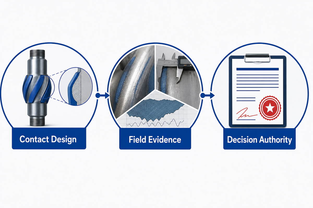
Stabilizer decisions become defensible when the team can connect the intended contact role to the as-run BHA, the well objective, measurements, inspection results, and current controlling documents. Hidden Bottleneck Map evidence helps avoid a one-signal conclusion; the Gauge-Loss Field Check Sheet keeps observations separate from acceptance authority. Use this engineering packet to frame the need, then move model-fit and commercial questions to the supplier’s solution page.
Research and review method
This guide separates public engineering evidence from China Welong’s first-party product and traceability statements. Sources include current API document notices, peer-reviewed wear and MWD research, BHA modeling studies, and an independent source-sufficiency review. No universal spacing, field rejection limit, or vendor-grade equivalence was inferred. China Welong’s technical team should review the article before publication.
Related Articles
- Integral blade or replaceable sleeve comparison — narrow the construction route after defining the contact objective.
- Non-magnetic stabilizer check — screen the MWD/LWD magnetic-compatibility requirement.
- Hardfacing grade selector — route a documented wear environment into the supplier’s grade system.
References & Sources
- Drilling Engineering Bottom Hole Assembly (BHA) — SSRN technical working paper.
- Modeling and Control of Drillstring Dynamics for Vibration Suppression — University of Texas repository.
- A Review of the Pipe Sticking Mechanism in Oil Well Drilling Operations — University of Baghdad, Journal of Engineering.
- Wear Behaviors of AISI 4145H Drilling Tool Steel — Materials / PubMed Central.
- Effect of Tungsten Carbide Morphology, Quantity, and Microstructure on Wear of a Hardfacing Layer — Metals.
- Microstructure and Wear of Ni-WC Hardfacing Used for Steel-Body PDC Bits — International Journal of Refractory Metals and Hard Materials.
- IMU/Magnetometer-Based Azimuth Estimation with Norm Constraint Filtering — Sensors.
- API Specification 7-1, Second Edition, Addendum 1 Notice — American Petroleum Institute.
- API Specification 7-1, Second Edition, Errata 2 — American Petroleum Institute.
![Choke & Kill Hose: [Field Guide]](https://welongoiltools.com/wp-content/uploads/2026/07/choke-kill-hose-guide-featured-1-150x150.png)