
Get in touch with Welong Company


Updated August 2026
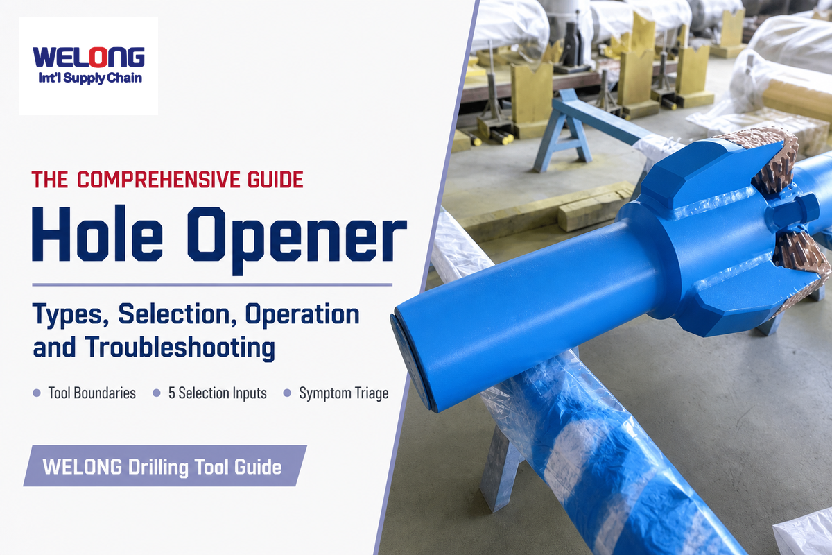
A hole opener is a drilling tool used to increase the diameter of a pilot bore or an existing drilled interval. Although the simple definition is useful, it doesn’t select a cutting structure, determine a pass plan, or set an operating limit. Those decisions depend on the formation, starting bore, target geometry, bottom-hole assembly, rig capacity, circulation program, and the actual tool documentation.
Direct answer: A hole opener is a drilling tool used to increase the diameter of an existing hole. It combines guidance, a cutting structure, and fluid paths for removing cuttings. Selection and operating limits must be verified for the specific tool, BHA, rig, formation, and drilling program.
What this guide helps you decide
- Whether the job calls for a fixed hole opener, another reaming tool, or an expandable underreamer.
- Which five inputs must be known before cutter or body design is compared.
- Why pass count and operating parameters can’t be copied from a universal rule of thumb.
- How to connect low penetration, torque spikes, vibration, poor cleaning, and wear to an ordered check.
What Is a Hole Opener, and What Is It Used For?
Hole openers increase the diameter of a bore that already has a pilot or smaller drilled section. IADC’s DDR Plus terminology describes it as a drill bit used for enlarging the hole. In oil and gas drilling operations, the enlarged interval can provide clearance for later drilling or casing installation. In horizontal directional drilling (HDD), the enlarged bore can prepare a path for product installation. Applications change, but the enlargement function remains the anchor.
What is a hole opener used for?
However, a hole opener does not remove the requirement for you to specify an entry bore. An under-gauge, unstable, poorly cleaned, or more tortuous pilot changes guidance, loading, and cuttings transport. It’s also not automatically a cure for poor hole geometry or hole quality: an AADE case analysis found that backreaming and hole enlargement didn’t reliably reduce measured tortuosity in the reviewed wells.
| It does | It does not prove by itself |
|---|---|
| Enlarge a known starting diameter | That the pilot is stable, clean, or on gauge |
| Apply a defined cutting structure at a larger radius | That one cutter type fits every layer in the interval |
| Provide fluid paths around the cutting area | That the rig and fluid program can transport the additional solids |
How Does a Hole Opener Enlarge a Pilot Bore?
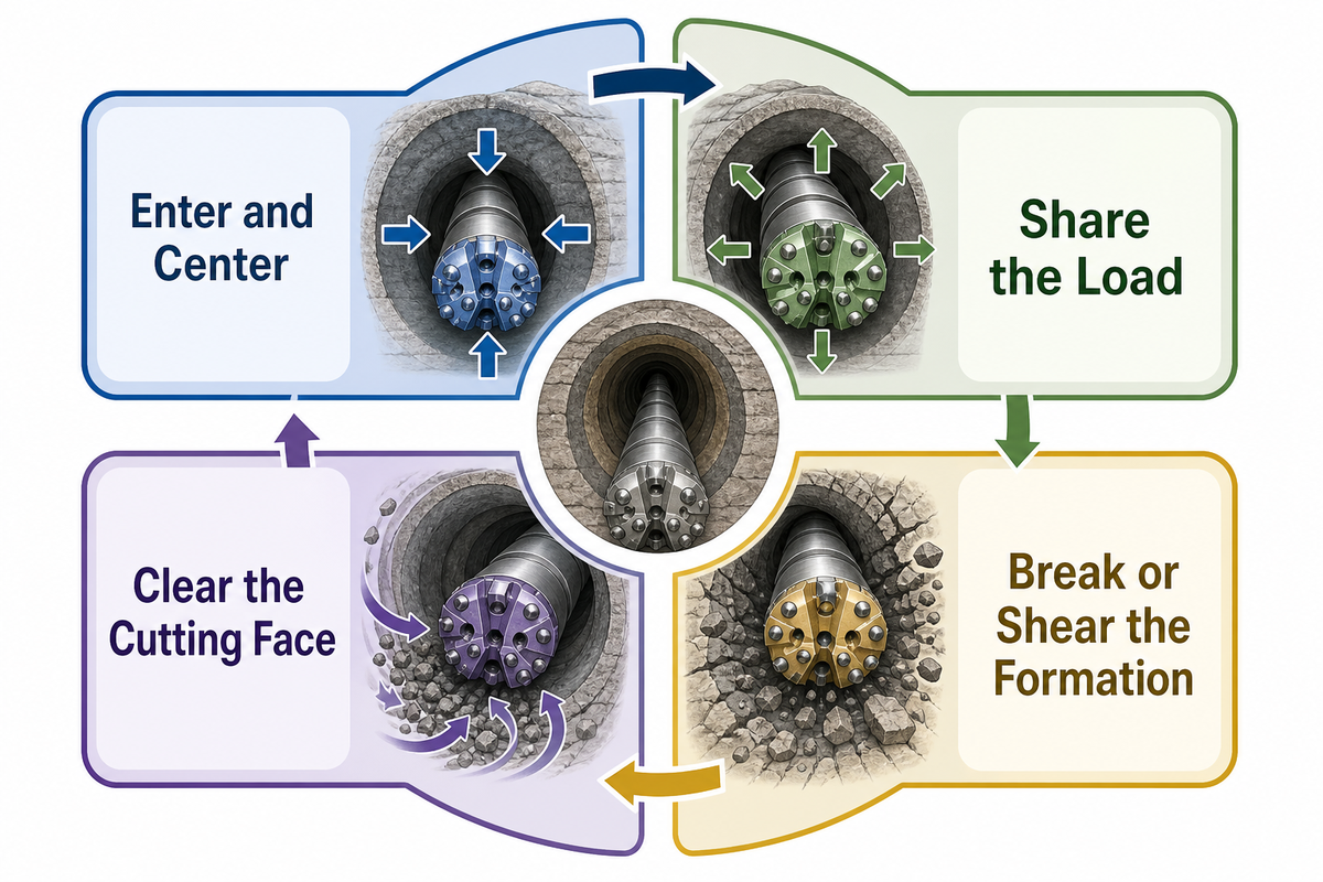
Hole opening is a coupled process, not just a larger cutter sweeping through rock. Within the assembly, the pilot or guide establishes the borehole path; the cutting structure engages material outside the starting diameter; the BHA transmits rotation and load; and circulating fluid must remove the extra cuttings without allowing them to be repeatedly ground or packed around the assembly.
How do hole openers work?
- Enter and center. During entry, the assembly follows the pilot or existing bore. Guidance condition and BHA stabilization influence how evenly the cutters engage.
- Share the load. Pilot, conditioning, or reaming elements take their assigned portion of the cut. An imbalance can show up as uneven wear, torque variation, or vibration.
- Break or shear the formation. Roller cutters crush and chip; fixed cutters shear. Real response depends on strength, abrasivity, impact, interbeds, and confinement.
- Clear the cutting face. Fluid cools and cleans the cutters and transports solids through the enlarged annulus. Even a clean pilot-hole program may become inadequate after diameter increases.
In 2025, a peer-reviewed reamer dynamics study modeled the interaction among drill string, reamer, wellbore, stabilizer, and operating variables. Its numerical results belong to that configuration, but its broader lesson transfers: vibration is a system response. One surface signal rarely identifies one cause without the rest of the operating record.
Working principle in one sentence
A hole opener must remain guided, distribute load across its cutting structure, and remove the extra solids at the same time; a weakness in any one of those functions can appear as a drilling-performance problem.
Main Hole Opener Types and Cutting Structures
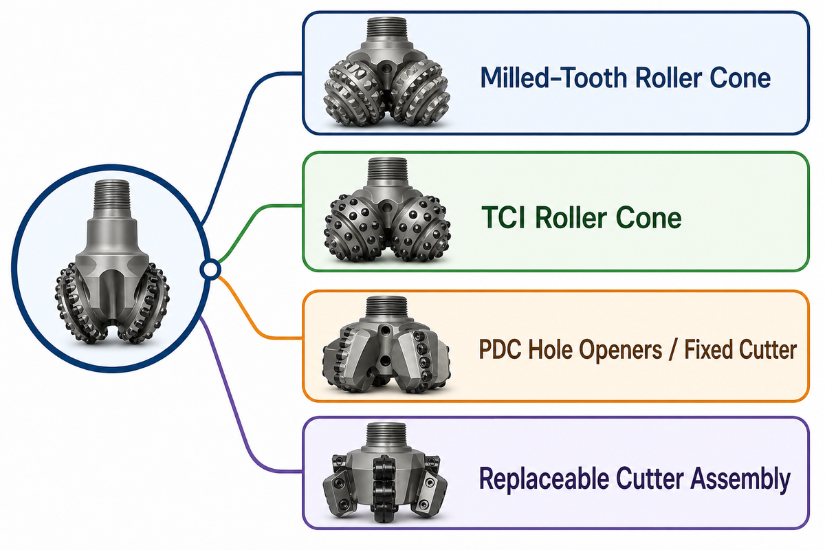
Tool names vary by sector and manufacturer, so compare cutting action and service implications before comparing labels. Formation strength alone is not enough. Abrasivity, broken rock, hard stringers, impact, directional changes, cleaning capacity, available load, tool-body alloy, expected tool life, and repair strategy can reverse a catalog-level choice.
| Family | Cutting action | Useful fit question | Limitation / inspection focus |
|---|---|---|---|
| Milled-tooth roller cone | Rolling cutters crush, gouge, and chip with steel teeth | Does the formation allow tooth penetration without destructive impact or rapid erosion? | Inspect tooth loss, erosion, bearing condition, and cone movement. |
| TCI roller cone | Crushing and chipping through tungsten-carbide inserts | Which insert shape and grade match strength, abrasivity, and impact? | Inspect cracked or missing inserts, gauge wear, sealed bearing condition where applicable, and retention. |
| PDC hole openers / fixed cutter | Continuous shearing with fixed cutters | Is the formation sufficiently drillable and stable for the cutter exposure and operating envelope? | Watch for cutter chipping, thermal damage, balling, imbalance, and gauge-pad wear. |
| Replaceable cutter assembly | Depends on installed cone or cutter module | Can worn elements be replaced and documented without compromising alignment or retention? | Verify fasteners, retention, seating surfaces, records, and post-repair gauge. |
Use a formation-based cutter type advisor to organize questions, not to bypass engineering review. Formation names such as shale, limestone, or granite can still hide changes in strength, abrasivity, fractures, pressure, and interbeds.
Hole Opener vs Reamer vs Underreamer: Where Is the Boundary?
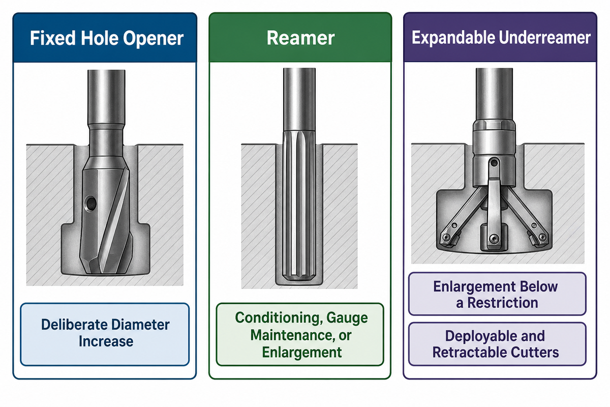
In common use, a hole opener describes a fixed-diameter tool whose main job is to enlarge an existing bore. A reamer may enlarge, condition, smooth, or maintain gauge depending on the drilling sector. Underreaming normally uses cutters that deploy below a restriction and retract for retrieval. Those statements are useful defaults, not universal naming laws. Compare the task, placement, geometry, and retrieval path before relying on the product label.
What is the difference between a hole opener and a reamer?
| Comparison field | Fixed hole opener | Reamer | Expandable underreamer |
|---|---|---|---|
| Primary purpose | Deliberate diameter increase | Conditioning, gauge maintenance, or enlargement | Enlargement below a restriction |
| Geometry | Fixed cutting diameter | Often fixed; sector-dependent | Deployable and retractable cutters |
| Retrieval question | Requires a compatible open path | Depends on body diameter and placement | Retracts through the restriction |
| Common ambiguity | Sometimes called a rock reamer | Can describe several distinct jobs | May be grouped broadly as hole-enlargement equipment |
For a deeper fixed-versus-expandable check, use the hole opener versus underreamer decision guide. If the uncertainty includes gauge conditioning and stabilization, review the roller reamer, hole opener, and stabilizer comparison.
The 5-Input Hole Opener Selection Check
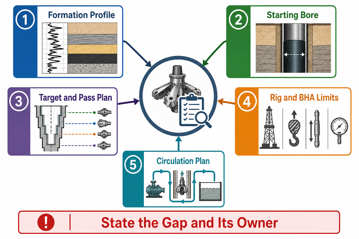
Start with the job, not the catalog. Five inputs create a common brief for drilling engineering, operations, procurement, and the tool supplier. If one row is unresolved, state the gap and its owner instead of hiding it inside a model recommendation.
| Input category | Evidence to provide | What it changes | Do not assume |
|---|---|---|---|
| 1. Formation profile | Lithology, strength range, abrasivity, fractures, interbeds, offsets | Cutting action, exposure, impact tolerance, wear plan | One rock name predicts the whole interval |
| 2. Starting bore | Measured diameter in in. or mm, interval length in ft or m, trajectory, cleaning record, restrictions | Guidance, centering, load sharing, retrieval risk | The pilot is on gauge and smooth |
| 3. Target and pass plan | Required final clearance, interval length, stage diameters, acceptance method | Body size, cutter work, solids volume, trip count | One enlargement ratio fits every job |
| 4. Rig and BHA limits | Connection, torque in N·m or lbf·ft, load in kN or lbf, rotation in rpm, stabilization and spacing | Tool compatibility and approved operating envelope | The tool rating alone is the system limit |
| 5. Circulation plan | Flow in L/min or gpm, pressure in bar or psi, fluid properties, returns and solids handling | Cutter cleaning, cooling, transport, pack-off exposure | Pilot-hole hydraulics remain adequate |
| Release check: placement | BHA drawing, tool order, spacing in mm or in., restriction and retrieval path | Load sharing, stability, access through restrictions | A correct tool can be placed anywhere in the BHA |
| Release check: connection | Connection identity, make-up procedure, inspection and traceability records | Assembly integrity and reactive-torque margin | Nominal thread labels prove compatibility |
| Release check: inspection | Pre-run gauge, cutter, bearing, body, jet and retention disposition | Run readiness and post-run comparison | Visual appearance replaces acceptance criteria |
| Release check: documents | Configuration drawing, controlled manual, limits, certificates and approval owner | Which claim is verified and who can release the run | A standard number covers the complete tool |
Unit-control example, not operating guidance: 26 in. equals 660.4 mm; 50 ft equals 15.24 m; 1,000 gpm is about 3,785 L/min; 3,000 psi is about 207 bar; and 20,000 lbf is about 89 kN. This QA check confirms 8.5 in. equals 215.9 mm, 10 in. equals 254 mm, 12.25 in. equals 311.2 mm, 14 in. equals 355.6 mm, 16 in. equals 406.4 mm, 17.5 in. equals 444.5 mm, 18 in. is 457.2 mm, 20 in. is 508 mm, 22 in. is 558.8 mm, 24 in. is 609.6 mm, 26 in. is 660.4 mm, 28 in. is 711.2 mm, 30 in. corresponds to 762 mm, 32 in. corresponds to 812.8 mm, 34 in. corresponds to 863.6 mm, 36 in. corresponds to 914.4 mm, 40 in. corresponds to 1,016 mm, and 42 in. corresponds to 1,066.8 mm. A controlled schedule should name one master unit, show any conversion, and prevent a copied number from losing its context.
This table is a gate, not an automated selector. Trenchless tooling guidance likewise connects geology, rig compatibility, maintenance, and fluid practice rather than promising one universal life result. After the five inputs are fixed, you can compare hole opener models and specifications without shifting the educational guide into a duplicate product page.
Have the five inputs, but an unresolved interface?
Use the checklist in your technical discussion. Its goal is to expose missing evidence before a configuration is quoted. Bring the starting bore, target diameter, formation profile, rig/BHA limits, circulation plan, and the source document that controls each operating limit.
How to Plan Diameter and Enlargement Passes
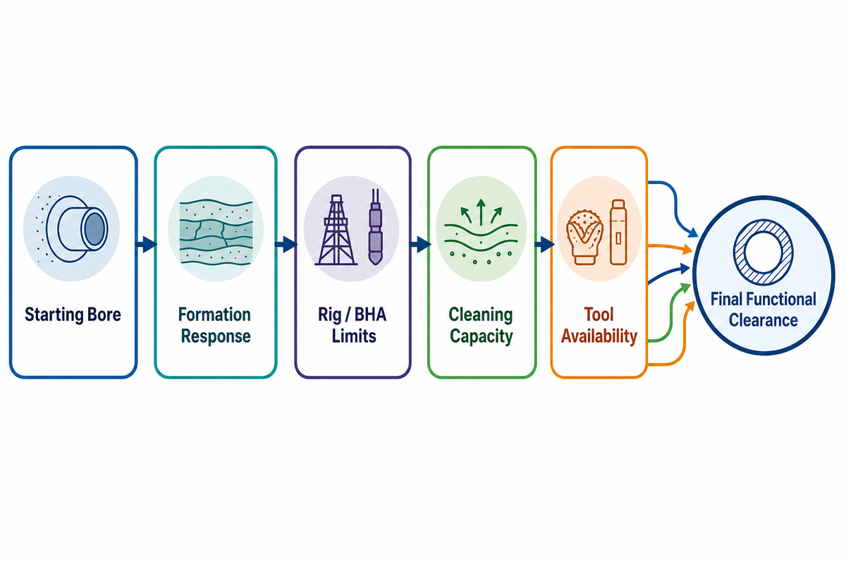
Pass planning begins with the final functional clearance and works backward through the starting bore, formation response, rig/BHA limits, cleaning capacity, and tool availability. A larger step concentrates more cutting work and solids generation in one run; extra stages add trips, handling, time, and additional opportunities for mismatch. Neither extreme is automatically safer or faster.
Illustrative arithmetic only: if a pilot is 12.25 in. and the required final diameter is 26 in., the total diameter increase is 13.75 in. That subtraction describes the job but does not prove whether the interval should be opened in one, two, or more passes. It says nothing about the removed cross-sectional area, the distribution of work across cutters, formation variability, rig margin, or cuttings transport. Those variables control the engineering decision.
Do not copy a ratio: a ratio observed in one field case or catalog example belongs to that formation, tool, BHA, rig, and objective. AADE case evidence also shows why “ream it and the hole will become smoother” is not a dependable pass-planning assumption.
Write the proposed stages beside their purpose: establish clearance, reduce load per stage, manage solids, pass a restriction, or meet a casing/product requirement. Then identify the limiting component for each stage. If the plan depends on an unverified torque margin, an assumed pilot condition, or returns that have not been modeled at the enlarged diameter, the plan is not ready for field release.
Set the Operating Envelope Before the Run
An operating envelope is a verified set of limits and observations for the selected tool in the planned assembly. It isn’t a list copied from a generic article. RPM, applied load, torque, flow, pressure, vibration, connection make-up, and stop criteria must agree across the tool documentation, BHA design, rig capability, operator program, and formation assumptions.
| Item | Authoritative source | Monitor together | Escalation signal |
|---|---|---|---|
| Rotation and applied load | Tool manual + drilling program | ROP, torque, vibration, returns | Unstable response or no progress |
| Torque and connections | BHA design + connection procedure | Rotation, stall events, pressure | Sudden spike, stall, suspected back-off |
| Flow and pressure | Hydraulics program + rig limits | Returns, solids, drag, losses | Rising pressure, lost returns, pack-off signs |
| Vibration | MWD/tool program | Torque, ROP, tool data quality | Program alarm or rapidly increasing severity |
A field guide for drill bits notes that bottom or fill contact can appear as changes in load or torque and stresses circulation and vibration monitoring. Those are useful relationships, but they aren’t universal hole-opener setpoints. The same boundary applies to research percentages: even a peer-reviewed improvement measured in one BHA can’t be pasted into another run plan.
The reactive-torque case deserves special treatment. An IADC/SPE case abstract explains that a sudden hole-opener or underreamer stall can apply left-handed torque below the stalled tool. That makes suspected loss of rotation a stop-and-assess event, not an invitation to push through with more load.
Pre-Run and Post-Run Inspection
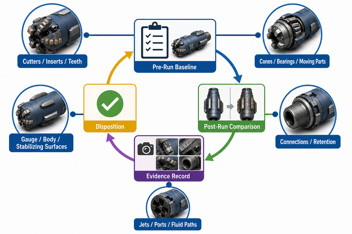
A repeatable inspection record connects what was installed, what the tool experienced, what changed, and whether it’s fit for another run. “Looks acceptable” isn’t a durable record. The IADC DDR Plus code set illustrates the value of structured drilling-condition records, but actual disposition still belongs to the manufacturer’s acceptance criteria and the operator’s process.
| Area | Before the run | After the run | Evidence |
|---|---|---|---|
| Cutters / inserts / teeth | Count, condition, orientation, retention | Map wear, chips, loss, thermal or impact signs | Photos tied to cutter position |
| Cones / bearings / moving parts | Movement and seal checks per manual | Play, seizure, leakage, heat evidence | Measured result and disposition |
| Gauge / body / stabilizing surfaces | Baseline gauge, dimensional precision, and damage survey | Uniform versus localized loss, wash, cracks | Measurement method and locations |
| Connections / retention | Correct components, clean condition, required records | Shoulder, thread, fastener, and back-off evidence | Traceable assembly and inspection record |
| Jets / ports / fluid paths | Configuration, security, unobstructed path | Plugging, erosion, wash, missing element | Configuration sheet and photos |
Compare the inspection map with the downhole run history. Localized gauge wear plus abnormal lateral response tells a different story from uniform abrasive wear with stable trends. If gauge, retention, connection integrity, or component condition can’t be confirmed against the acceptance criteria, the correct disposition is escalation, not an undocumented rerun.
Troubleshooting by Symptom, Not Guesswork
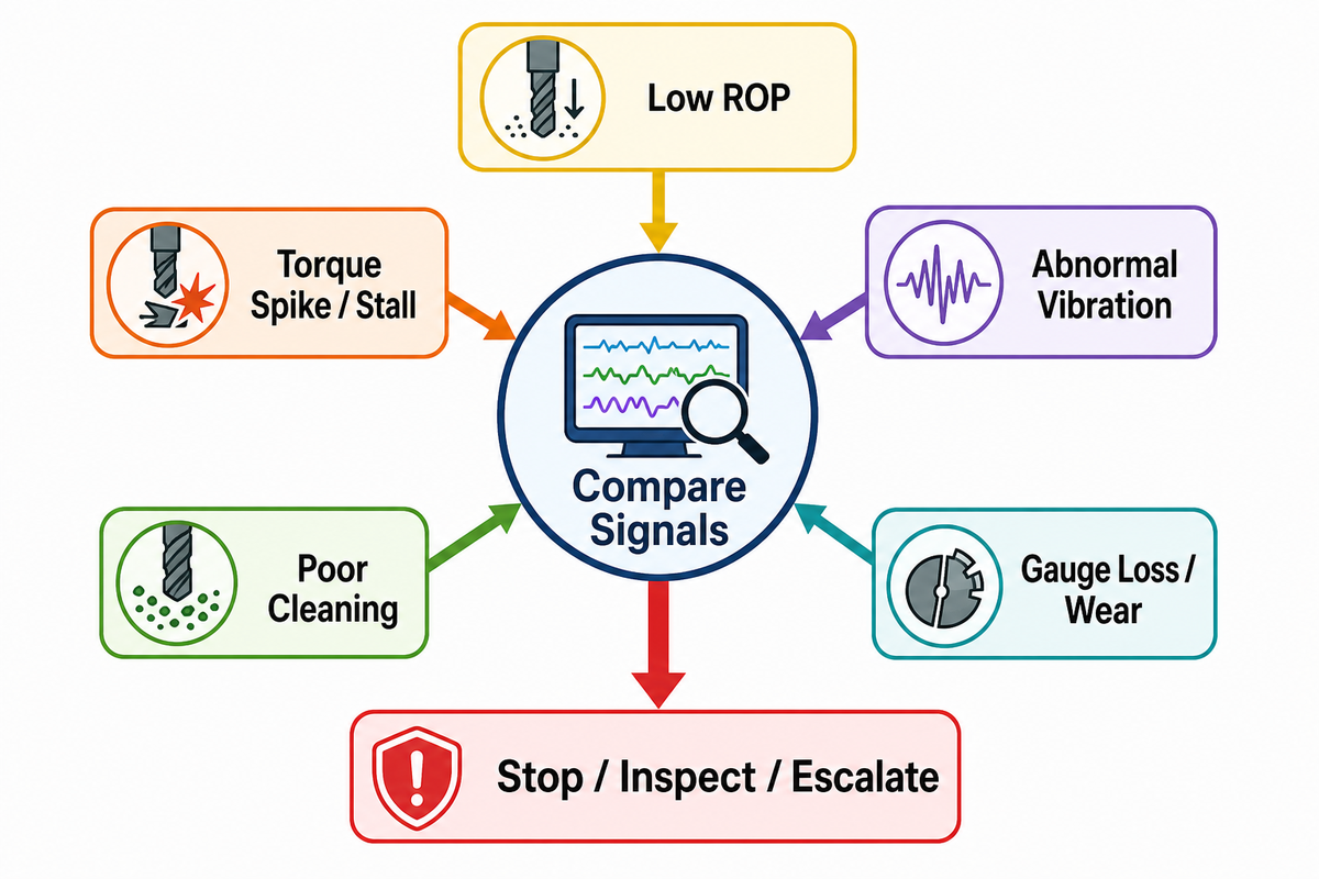
The table below is a conversation and recordkeeping aid assembled from the multi-source review. It isn’t field instruction and doesn’t replace the drilling program. A peer-reviewed reamer vibration study likewise treats response as a coupled drill-string, tool, and wellbore problem. Each symptom has several plausible causes, so the first task is to compare signals and check the safest evidence before changing an input.
| Symptom | Possible causes | Check in order | Unsafe assumption | Stop / inspect / escalate |
|---|---|---|---|---|
| Low ROP | Cutter mismatch; dull structure; poor cleaning; imbalance; vibration | Baseline trend → torque/pressure/vibration → returns → formation/tool assumptions → inspection | More load or speed must restore progress | Near-zero progress with abnormal torque, pressure, or vibration |
| Torque spike / stall | Reactive torque; stick-slip; pack-off; formation change; damaged cutters; connection issue | Confirm rotation → classify signature → check pressure/returns → vibration/trajectory → BHA limits | Every spike is only harder rock | Suspected stall, lost rotation, back-off, or combined torque/pressure anomaly |
| Abnormal vibration | Operating point; stabilization; imbalance; tortuosity; wear; hydraulic instability | Program limits → rotation/load/torque → stabilization/spacing → on/off-bottom comparison → inspection | Higher RPM or load is a universal cure | Rapid increase, combined instability, tool-data loss, or program alarm |
| Poor cleaning | Flow/rheology mismatch; lost returns; excessive solids generation; stagnant zones; balling; instability | Returns/pressure → enlarged-annulus calculation → drilling mud/fluid and pump capacity → solids handling → conditioning procedure | Pilot-hole hydraulics remain adequate | Rising pressure, lost returns, drag, inability to circulate clean, or pack-off signs |
| Gauge loss / wear | Abrasivity; vibration; cutter mismatch; poor cooling; imbalance; tortuosity; retention damage | Pre/post gauge → wear map → vibration/hydraulics → pilot/opener comparison → full component inspection | Wear can be offset with more load | Uncertain gauge, damaged retention, missing evidence, or wear outside manual criteria |
The highest-confidence relationship is the stall/reactive-torque mechanism. The lowest-confidence area is a universal hole-cleaning threshold: the reviewed public sources don’t provide one. That gap is why the table tells you what to verify and when to escalate, not what exact flow or pressure to apply.
Current Design Priorities: Maintainability, Stability, and Verifiable Limits
Useful current-direction research asks what a buyer can verify. A published patent may disclose staged cutter placement or replaceable cutter shafts, as in US5337843A, but a patent isn’t proof that the design outperforms another tool in the field. A vendor statement isn’t an operating envelope unless the applicable configuration and test basis are supplied.
| Priority | Buyer question | Evidence required | Trade-off to review |
|---|---|---|---|
| Maintainability | Which cutters, cones, jets, or wear parts are replaceable? | Procedure, retention method, gauge check, repair record | Field repairability versus alignment and QA control |
| Stability | How are guidance, load sharing, and imbalance managed? | BHA model, placement drawing, run evidence, inspection map | Stabilization versus contact, restriction, and hydraulic effects |
| Verifiable limits | Which document controls rotation, load, torque, flow, pressure, and stop criteria? | Configuration-specific manual and approved program | Conservative margin versus drilling efficiency |
| Standards scope | What exactly does an API statement cover? | Component, edition, process, inspection, marking, and certificate scope | Clear evidence versus broad marketing shorthand |
API’s 2025 Addendum 1 affects the second edition of API Specification 7-1, Rotary Drill Stem Elements. It doesn’t establish that a complete hole opener is compliant. Ask which component, connection, manufacturing step, inspection, marking, and record the supplier means. That question is more useful than repeating “API 7-1” without a scope.
Frequently Asked Questions
How do you choose a suitable hole opener?
Start with five job inputs, not a model table.
Record the formation profile, starting-bore condition, target diameter and pass plan, rig/BHA limits, and circulation plan. Link each input to evidence and a decision owner. Then compare cutting action, body design, maintenance requirements, and configuration-specific limits. If any system limit is missing, the provisional selection requires review from the drilling engineer and tool supplier.
What tool is used to widen a drilled hole?
A fixed hole opener is one tool used to enlarge an existing drilled bore. Reamers and underreamers cover related but different conditioning, placement, and retrieval jobs.
The correct tool family depends on the task and restriction. A reamer may condition, maintain gauge, or enlarge. An underreamer deploys below a restriction and retracts. Define purpose, placement, fixed or expandable geometry, target diameter, and retrieval path before turning “widen the hole” into a product request. Confirm the manufacturer’s terminology on the selected configuration because trade labels can overlap across sectors.
Is a reamer bit the same as a hole opener?
The terms overlap, but they should not be assumed identical. Depending on the drilling sector and configuration, a reamer may condition, maintain gauge, or enlarge.
A hole opener usually emphasizes fixed-diameter enlargement of a pilot bore. “Reamer” can mean conditioning, gauge maintenance, or enlargement depending on the sector. Compare the intended job, tool placement, cutting geometry, and diameter change rather than treating the label as a complete specification. Also verify whether the body is fixed or expandable and how it will pass the planned restrictions.
What is the difference between a hole opener and an underreamer?
A hole opener is generally fixed at its cutting diameter; an underreamer deploys and retracts. Its expandable geometry creates clearance below a restriction, then retracts for retrieval.
The expandable geometry allows an underreamer to create clearance below a restriction and then retract for retrieval. Actual placement, activation, diameter, and operating limits still belong to the selected system.
How should hole opener size and pass count be chosen?
Choose stages from verified job and system constraints, not a universal enlargement ratio. Work backward from required clearance while checking formation, rig/BHA margin, hydraulics, and tool availability.
Work backward from the required clearance and acceptance method. Check starting-bore condition, formation variability, cutter work, rig/BHA margin, solids generation, hydraulics, and available tool sizes. A larger jump concentrates work and cleaning demand; extra stages add trips and handling. The limiting component and evidence quality should decide the plan. Write the purpose and acceptance evidence for every proposed stage, then confirm that the rig, connections, stabilization, and fluid program are evaluated at that stage’s enlarged geometry. If a stage depends on an assumed pilot condition, unverified torque margin, or returns that were modeled only for the pilot bore, it is not ready for release. The drilling engineer and tool supplier should resolve those gaps before the plan becomes field instruction.
When should roller-cone and PDC designs be compared?
Compare cutting structures after formation and system limits are known. Strength, abrasivity, fractures, impact, cleaning capacity, inspection needs, and repair strategy can change the answer.
Strength, abrasivity, fractures, impact, interbeds, cleaning capacity, directional behavior, inspection needs, and repair strategy can all affect the answer. A hard-versus-soft label is not enough. Require tool-specific operating and repair limits for the actual configuration.
What should be checked before a hole opener run?
Confirm configuration, condition, connections, gauge, fluid paths, and the approved operating envelope. Then match diameter, connection, placement, and all verified limits to the current drilling program.
Record cutters or inserts, cones and bearings where applicable, gauge, body and stabilizing surfaces, connections, retention features, jets, and replaceable assemblies. Match diameter, connection, tool placement, and limits to the current program. Missing inspection evidence or an unresolved mismatch should trigger escalation rather than compensation with more load.
Move from the guide to a configuration review
Bring the five inputs, operating-limit sources, and inspection requirements. Welong’s commercial page can then handle model and specification comparison without duplicating this guide.
How this guide was prepared
The public-data-only Hole Opener guide separates educational decision support from Welong’s existing commercial solution page. Evidence was reviewed across IADC, API, AADE, IADC/SPE, peer-reviewed research, major-tool guidance, trade material, and patents. Configuration-specific numbers returned by the research agent were excluded from universal recommendations. Company identity was checked against Welong’s public company page; no unpublished field result or individual credential is claimed.
Related Hole Opener resources
References & Sources
- DDR Plus Code Set Version 2.0 International Association of Drilling Contractors
- Vibration behavior analysis of reamers based on drill string dynamics Scientific Reports, 2025
- The Limits of Backreaming, Hole Enlargement, and Casing to Mitigate Wellbore Tortuosity AADE, 2017
- Case Study: Reactive Torque Failure Prevention IADC/SPE Drilling Conference, 2018 (abstract reviewed)
- API Specification 7-1 Addendum 1 American Petroleum Institute, 2025
- Knowledge Is Power When Selecting Tooling Trenchless Technology HDD Guide, 2024
- US5337843A: Hole opener for the top hole section of oil/gas wells design disclosure only
![Casing, Tubing & Drill Pipe Elevators [Field Guide]](https://welongoiltools.com/wp-content/uploads/2026/09/casing-tubing-drill-pipe-elevators-guide-featured-768x512.png)
![Choke & Kill Hose: [Field Guide]](https://welongoiltools.com/wp-content/uploads/2026/07/choke-kill-hose-guide-featured-1-150x150.png)