
Get in touch with Welong Company

Industrial Forgings (Casting Division) is best understood as an organizational label, not a single manufacturing process. Forging shapes solid metal through compressive force, while casting pours molten metal into a mold and lets it solidify. This guide explains what forging changes inside the metal, why defects form, and how to interpret inspection evidence without confusing “tested” with “accepted.”
If you are comparing suppliers or preparing a drawing-specific inquiry, that commercial intent belongs on China Welong’s industrial forgings solution page. This article stays on the educational side of the topic: process history, metal flow, discontinuity mechanisms, test limitations, and traceability.
The short version
- Forging and casting are different routes even when one division manages both.
- Grain flow can help when it follows the service load path, but directionality prevents an “always stronger” rule.
- A defect name, an NDT method, and a rejection decision are three separate things.
- A credible evidence package connects 5 links: drawing, part, heat or lot, test report, and release record.
What “Industrial Forgings (Casting Division)” Actually Means
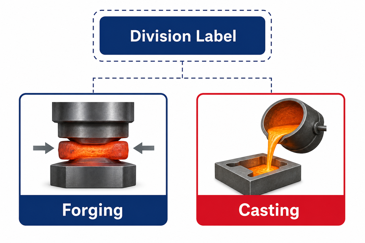
In practical terms, the phrase means forged products are handled within a business unit that may also manage casting. It does not mean the casting process and forging process become interchangeable. Metal state, tooling, likely discontinuities, and inspection questions all remain different, so each route begins a different evidence chain.
| Route | Starting condition | How shape is created | First evidence question |
|---|---|---|---|
| Forging | Solid metal heated or worked within a controlled range | Hammer or press applies compressive force | What stock, heat, deformation, and heat-treatment history applies? |
| Casting | Molten metal | Metal fills and solidifies in a mold cavity | Which casting methods, feeding plan, and solidification controls apply? |
| Part machined from bar | Usually rolled or extruded wrought bar | CNC machining removes material | What upstream bar route and orientation does the certificate represent? |
That third row matters. “Machined bar” is not a metallurgical route parallel to forging or casting. Bar is commonly a wrought stock form, and machining is a later removal operation. Treating all 3 labels as equivalent can hide the upstream history that actually controls grain structure and mechanical properties.
What Forging Changes Inside the Metal
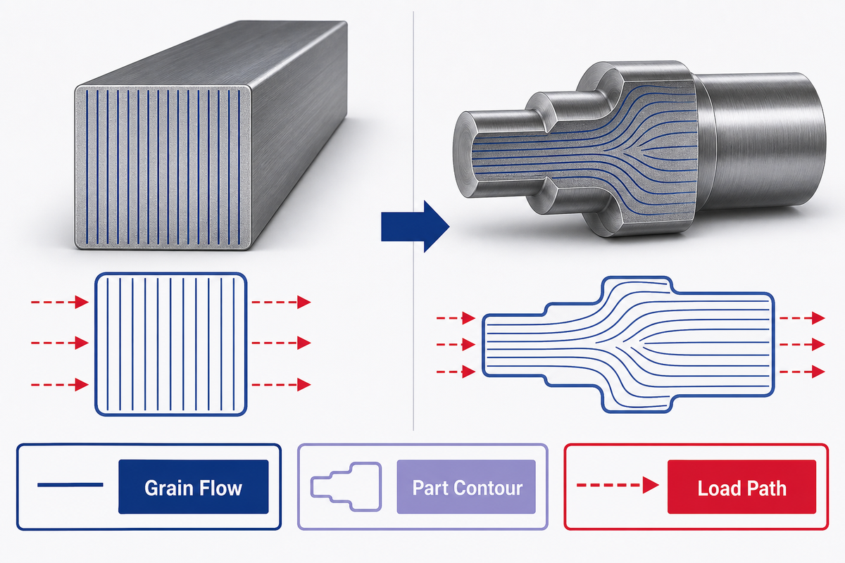
Forging plastically deforms solid metal, changing its shape and the orientation of features within its microstructure. With suitable temperature, reduction, and die design, the worked grain flow can follow the part contour and support the intended load path. That benefit is directional, not a universal strength guarantee.
The Forging Industry Association describes grain flow as constituent orientation caused by working. This is why forging dies and forging techniques matter: they determine how metal moves around a web, bore, shoulder, or flange. Properly designed flow can reduce the need to cut across critical fibers during additional machining.
Yet grain flow is only 1 part of the result. Alloy chemistry, cleanliness, forging temperature, accumulated reduction, recrystallization, heat treatment, and cooling history also affect properties. Corrosion resistance usually follows material and heat-treatment condition more than the simple fact that a part was forged. The honest statement is “forging can improve a designed property,” not “forging always makes every axis stronger.”
This is especially relevant for shafts, rings, turbine components, and aviation forging applications where load direction is known. It is less decisive when a component sees complex multi-axial loading, when internal cavities dominate the geometry, or when later machining removes much of the directional structure the designer expected to keep.
The Industrial Forging Process, from Stock to Traceable Part
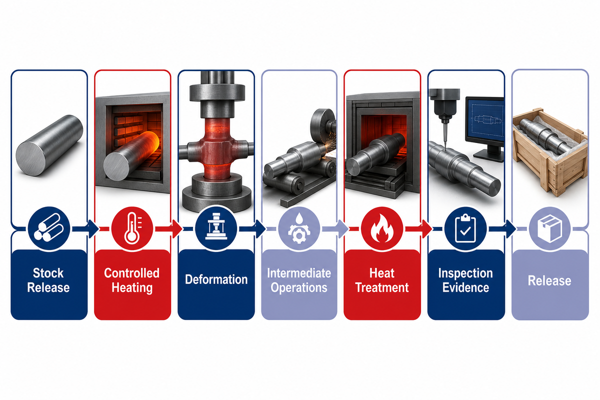
An industrial forging is the outcome of a sequence, not a single press stroke. That directionality only makes sense when the full process history stays visible. The useful way to read that sequence is the Flow–Defect–Evidence Chain: every process event changes metal flow, creates or exposes a possible discontinuity, and should leave a record that can be tied to the finished part.
- Stock release: ingot, billet, or bar obtains a heat identity and material route.
- Heating and descaling: temperature uniformity and surface condition affect flow and scale-related defects.
- Preforming and deformation: hammer forging or press forging forms the stock toward the required section.
- Reheating, trimming, or piercing: intermediate operations influence laps, folds, material loss, and geometry.
- Heat treatment: the cycle determines microstructure and mechanical properties within the material specification.
- Machining and inspection: surfaces are made accessible, dimensions are set, and NDT is conducted at the specified stage.
- Release: test results, identity, concessions, and final disposition connect to the shipment.
A certificate that shows the correct alloy but cannot connect the heat number to the marked part covers only step 1. A clean ultrasonic report without the specified inspection stage may miss material removed later or surfaces not yet prepared. The chain works only when process and document timing match the drawing and purchase specification.
Open-Die, Closed-Die, and Rolled-Ring Forging Use Different Flow Paths
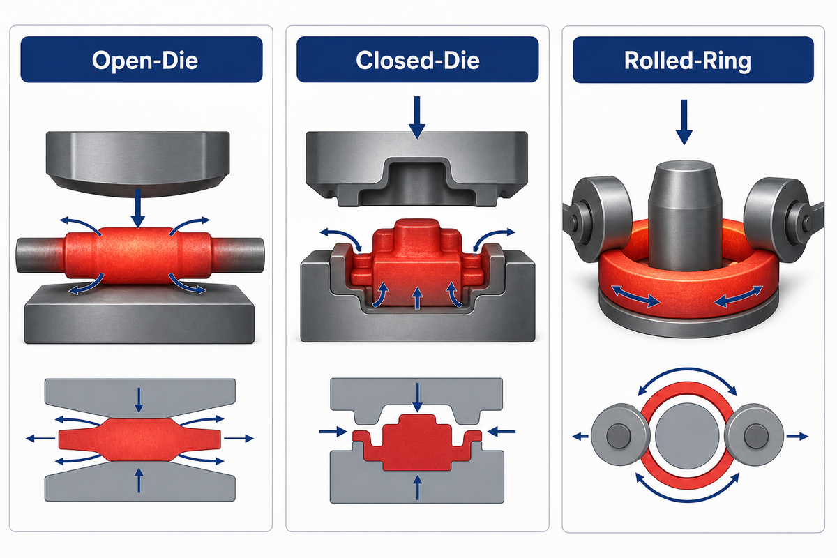
Open-die forging, closed-die forging, and rolled-ring forging all deform solid metal, but they restrict flow differently. This route-level view turns process history into the drawing and inspection questions that follow. Open dies permit greater lateral flow, impression cavities constrain the stock into a specified shape, and ring rolling enlarges a pierced blank between rolls. These distinctions influence tooling, allowance, repeatability, and defect probability.
| Route | Flow control | Typical geometry logic | Watch point |
|---|---|---|---|
| Open-die forging | Relatively free lateral flow between simple tools | Large shafts, blocks, disks, and low-volume shapes | Overlap, reduction history, center soundness, and machining allowance |
| Closed-die forging | Metal fills shaped die impressions | Repeat parts with more complex external shape | Underfill, laps, flash, die wear, and draft |
| Rolled-ring forging | Radial and axial rolls expand a pierced blank | One-piece rings for bearings, flanges, and rotating equipment | Wall uniformity, ring growth, surface condition, and scan geometry |
Size and weight alone don’t determine a route. Production volume, tooling lead time, section transitions, material forgeability, final tolerance, and the level of machining needed all alter the conclusion. The route should be derived from the drawing and service requirement, not a generic process bias. For a drawing-led comparison, the forging route selector turns those variables into a structured review.
Forging vs Casting vs Parts Machined from Wrought Bar
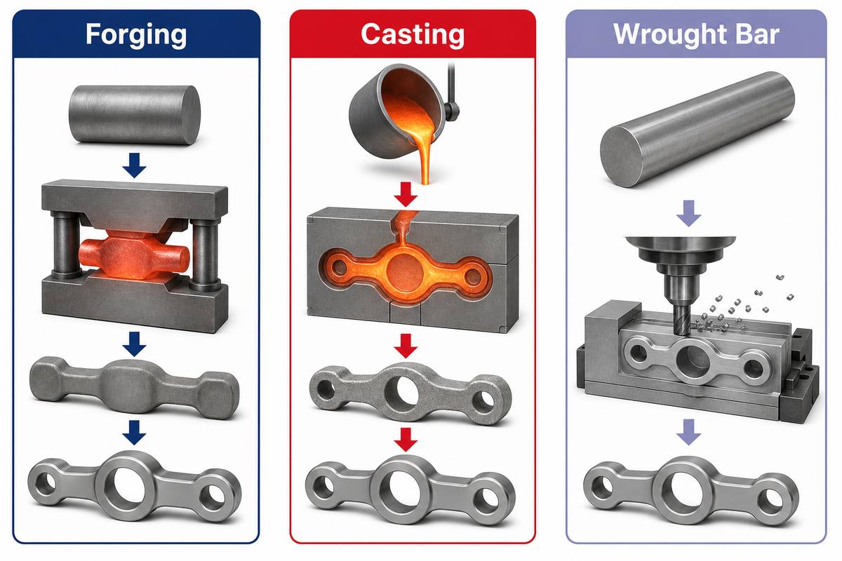
Choosing between forging and casting begins with the load path and geometry, while a bar-machined route additionally involves an upstream wrought process plus material removal. The difference between casting and forging is therefore a difference in material state, flow history, geometry options, and evidence requirements. To compare fairly, the materials history, forming technique, and finishing must be isolated. The “best process” shortcut is overly simplistic for designs with complex geometry or combined loading.
| Design condition | Route often favored | Reason to verify |
|---|---|---|
| Known dominant load direction | Forging | Confirm grain flow and retained fiber after machining |
| Deep internal cavities or integrated passages | Casting | Review feeding, porosity risk, and inspectability |
| Simple prismatic part, low quantity | Machined wrought bar | Check bar orientation, section availability, and material waste |
| Thin intricate walls at high detail | Investment casting | Confirm alloy, hot-tear risk, and acceptance plan |
| High-volume nonferrous housing | Die casting or permanent mold casting | Check pressure integrity, porosity, and heat-treatment limits |
| Very large valve bodies | Sand casting or engineering review | Balance shape integration, wall transitions, weld repair rules, and NDT access |
The distinction between casting and forging is therefore not a matter of “winner and loser.” Metal casting may suit components with complex geometries, integrate internal features that no forging tool can produce directly, and sometimes require less machining. Forged parts may be capable of directional flow following a contour. Wrought bar may be suitable for straightforward, low-volume metal components. The appropriate decision hinges on the precise drawing, alloy, load type, volume, and acceptance criteria.
That same discipline applies to a casting vs forging comparison for automotive hardware, industrial machinery, or pressure-retaining equipment. One foundry route may integrate shapes that would otherwise need assembly, while forging may place worked flow around a critical contour. The route name is only the start of the engineering review.
Why Forging Defects Form: A Mechanism-Based Atlas
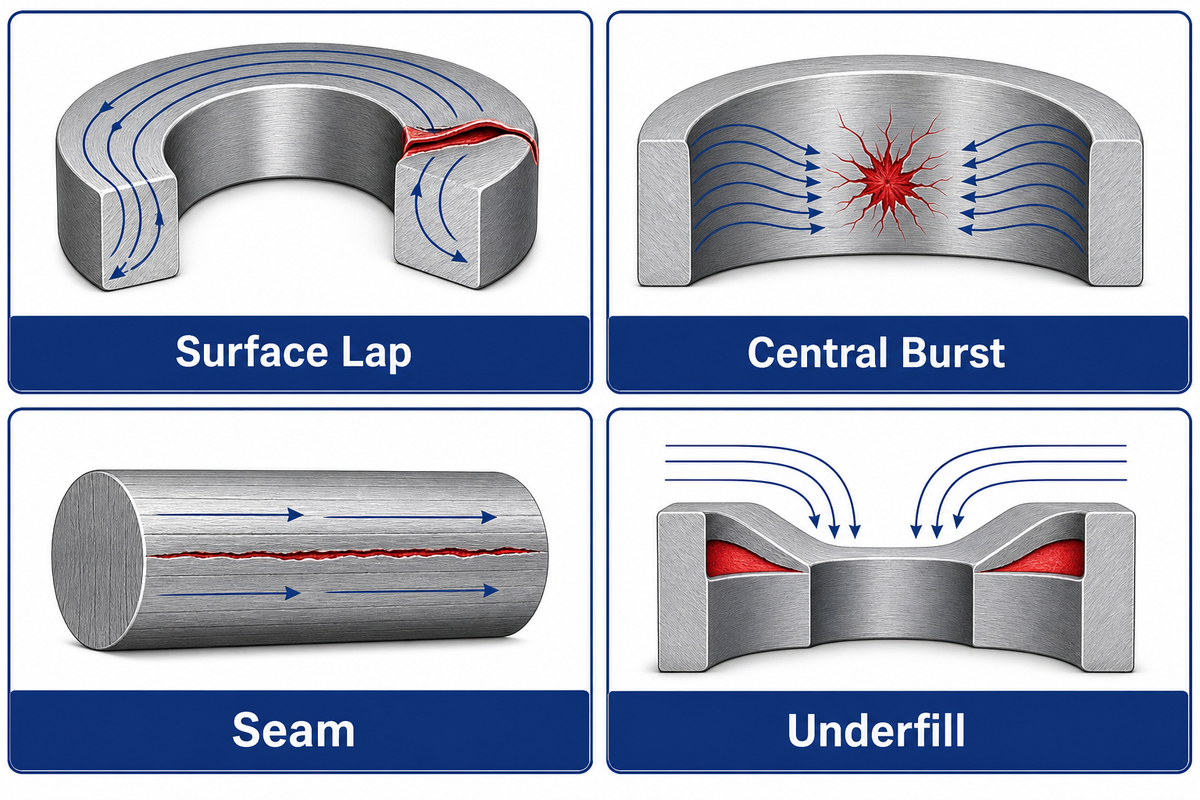
Forging defects should be named by mechanism, location, and orientation before anyone discusses disposition. Once the route is selected, the review moves from process choice to discontinuity mechanism. A lap is not a burst, and a seam is not a flake. The same visual word may also be used loosely in shop conversation, so the investigation must return to process history and examination evidence.
| Discontinuity type | Formation mechanism | Likely location or orientation | Do not assume |
|---|---|---|---|
| Lap or fold | A surface folds over and is worked into the part | Near flow reversals, sharp transitions, or die-fill problems | Every linear indication is a lap |
| Cold shut | Converging surfaces fail to bond under unfavorable flow, temperature, or scale conditions | Die-fill junctions and meeting streams | It is identical to a casting cold shut |
| Seam | A feedstock surface discontinuity elongates during working | Along the working direction | The forging operation created the original defect |
| Central burst | Internal tensile stress or unfavorable deformation state opens a center crack | Internal center region | One universal reduction ratio prevents it |
| Flake | Hydrogen, cooling, section size, and stress history combine to form internal fissures | Internal, often after cooling | A clean surface rules it out |
| Underfill | The stock does not fill the intended die impression | External geometry, ribs, and thin transitions | Machining allowance will always remove it |
| Decarburization | A heated steel surface loses carbon through atmosphere exposure | Near-surface layer | Bulk chemistry represents the finished surface |
| Grinding crack | Local heat and stress during finishing open a surface crack | Ground or blended areas | The indication must have formed during forging |
| Scale pit | Oxide is pressed into the hot surface | Surface | Every pit has equal depth or relevance |
Finding a discontinuity is not the same as rejecting a part. Acceptance depends on the governing specification, examination stage, location, orientation, size, class or quality level, and any approved disposition. The defect atlas helps ask the right questions; it does not replace engineering acceptance criteria.
The Defect-to-Test Map: What Inspection Methods Can Miss
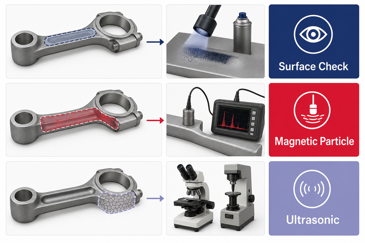
The Defect-to-Test Map connects a suspected discontinuity to a suitable examination method and its blind spots. No method sees every flaw. Detection depends on part geometry, surface condition, flaw orientation and depth, calibration, equipment, coverage, and operator variables, so NDT should never be described as 100% deterministic.
- Visual and dimensional examination is useful for shape, surface condition, and size, but weak for hidden internal discontinuities.
- Magnetic-particle testing finds surface and near-surface indications in ferromagnetic metal. ASTM A966/A966M-15(2025) notes that AC examination is primarily surface limited; DC practice under ASTM A275/A275M is used when subsurface indications are sought.
- Liquid penetrant testing finds surface-breaking discontinuities on suitable nonporous surfaces. It supplies no subsurface coverage.
- Ultrasonic testing: addresses internal reflectors, but probe access, beam angle, surface, attenuation, near-field behavior, and reflector orientation affect sensitivity and sizing.
- Hardness, tensile, and impact testing: sample mechanical properties at specified locations. They are not a complete defect map for the whole component.
ASTM A388/A388M-26 covers contact pulse-echo ultrasonic examination of heavy steel forgings and requires the ultrasonic quality level to be stated as an order requirement. ASTM A275/A275M-23 is equally instructive: it supplies a magnetic-particle procedure but does not provide universal acceptance standards or recommended quality levels.
Personnel qualification is another separate control. ISO 9712:2021 defines a third-party certification model for industrial NDT personnel. Employer-based systems can instead rely on an approved written practice. The purchase requirement should identify the applicable scheme rather than assuming one credential fits every order.
An inspection method explains how a test is performed. The order’s acceptance basis explains how the result is judged.
How to Read a Forging Inspection Package
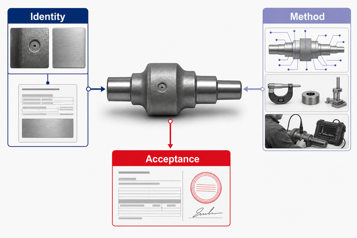
The Forging Evidence Ladder has 5 levels: identity, process, method, result, and acceptance. Each level answers a different question. Technically plausible reports can still fail to prove conformity when they do not identify the tested part, define coverage, or name the acceptance basis.
- Identity: purchase order, part number, drawing revision, heat or lot, quantity, and part marking.
- Process: material grade, stock route when required, forging condition, heat-treatment condition, and inspection stage.
- Method: written procedure, equipment, calibration reference, test surface, coverage, scan direction, and examiner qualification scheme.
- Result: indication location and size, dimensional values, hardness or mechanical results, and any retest.
- Acceptance: named specification, edition, class or quality level, drawing note, concession, and final disposition.
| Evidence check | Question to answer | Why it matters |
|---|---|---|
| Drawing | Is the revision identical? | Coverage and acceptance notes may have changed |
| Part identity | Does marking match the report? | Prevents record-to-part substitution |
| Heat or lot | Does it match the material certificate? | Connects chemistry and stock history |
| Inspection stage | When was the examination performed? | Surface and volume accessibility change |
| Coverage | Which surfaces and volume were examined? | Method names alone do not create a coverage map |
| Calibration | Which reference and sensitivity were used? | Supports repeatable interpretation |
| Acceptance basis | Which document, edition, and level apply? | Converts observations into a disposition |
| Release | Who approved shipment and any concession? | Closes the evidence chain |
The ladder exposes a common paperwork gap. “UT completed, no relevant indications” may describe a result, but it does not tell you whether the whole volume was accessible, which calibration block was used, what quality level governed, or whether the report belongs to the shipped piece. Method evidence proves an examination occurred; acceptance evidence explains how the result was judged.
For current work, also verify document currency. ASTM’s steel standards index lists A388/A388M-26 and A788/A788M-26a among current references, while A966/A966M was reapproved in 2025. The newest edition should not be substituted automatically if the contract names a different edition; the order controls unless the parties formally revise it. The forging material and standard review provides a separate drawing-specific checkpoint.
A Five-Link Traceability Check for Buyer-Side Verification
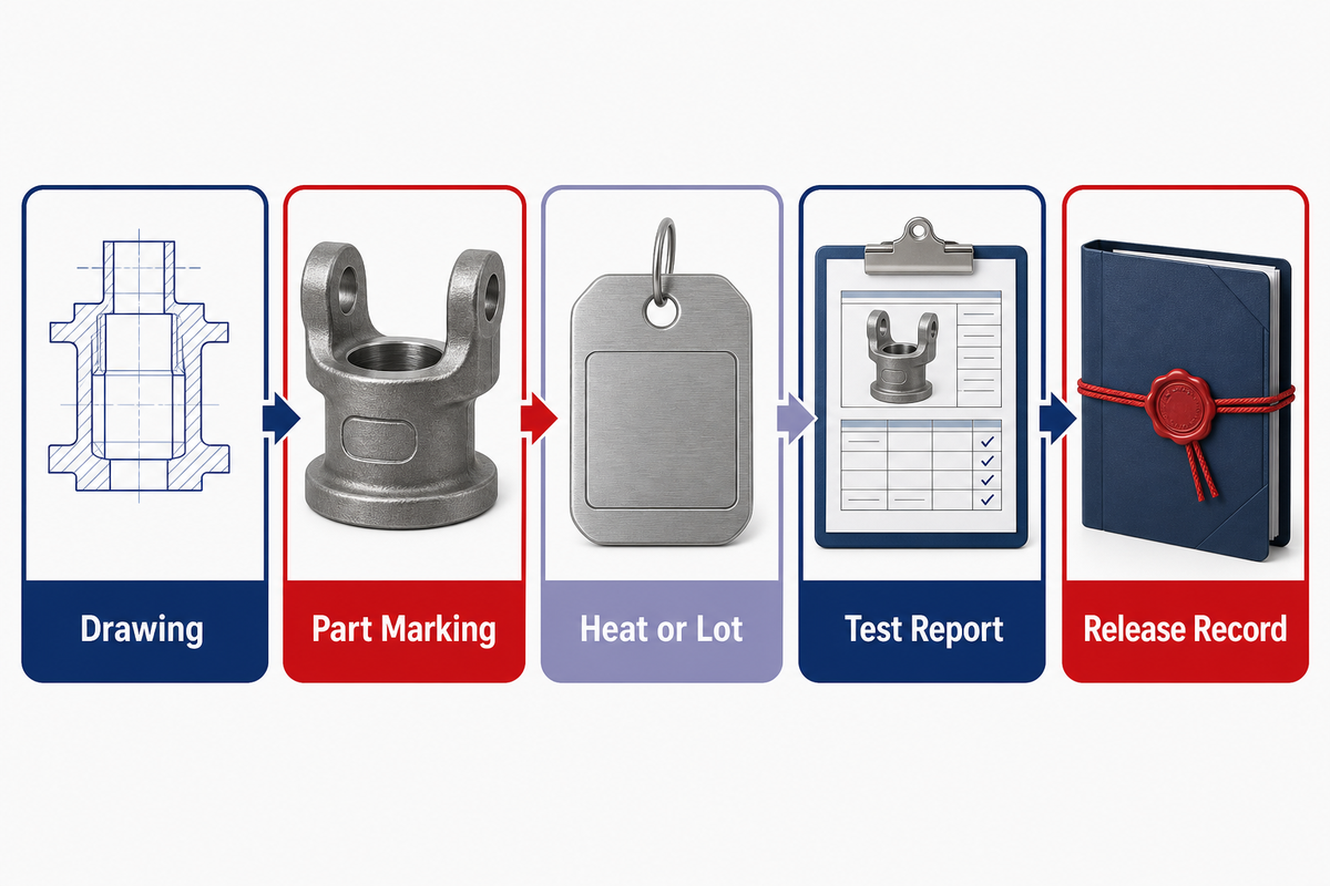
The Five-Link Traceability Check follows drawing, part marking, heat or lot, test report, and release record. If any link points to a different identity, revision, or quantity, the evidence chain is incomplete. This check is simple enough to use during document review before shipment.
Consider a ring marked with heat H2407. The material certificate shows H2407, but the ultrasonic report lists batch H2401 and an older drawing revision. All values may look reasonable, yet the report cannot be assumed to cover the ring. The correct response is an identity reconciliation, not a debate about whether the UT graph “looks clean.”
Worked example (illustrative, not a product specification)
A purchase order calls for 2 rings, each 1,200 mm outside diameter, 800 mm inside diameter, 180 mm high, and about 940 kg, with a final dimensional tolerance of 1.0 mm and a 0.5 mm flatness limit. Revision C requires 100% ultrasonic coverage after heat treatment and before a 12 mm machining allowance is removed. The submitted report covers 1 ring to revision B and lists a 6 mm allowance. Every value is plausible, but the identity, quantity, revision, and inspection-stage mismatch prevents the report from proving conformity.
To show how a record can be checked, the same purely illustrative plan could list a 2.25 MHz probe, a 20 mm scan index, a maximum 40 °C surface temperature, a 4 h calibration-recheck interval, a 6.3 µm machined finish, a 240–280 HBW hardness window, an 8 mm marking height, a 150 mm minimum finished wall, a 30 min witness hold, and a defined record-retention period. A matching sample drawing might also identify 3 mm stock removal per face, 0.8 mm total runout, a 1.5 mm edge break, a 25 mm reference step, 45° and 70° scan angles, and a 5 MHz second probe. These are sample fields, not recommended acceptance limits; the drawing and purchase specification must supply the real values.
Run the same check backward. Does the release note list the same quantity as the packing list? Does each report identify the exact inspection stage? If repaired areas or concessions exist, can they be traced to the drawing location and final disposition? These checks make a document package auditable without pretending paperwork can replace physical verification.
When the educational review is complete and the task becomes drawing-specific, use the industrial forgings solution page for the commercial path. Keeping that handoff explicit prevents this guide from duplicating supplier, lead time, quotation, and RFQ content.
What 2025–2026 Signals Mean for Forging Buyers
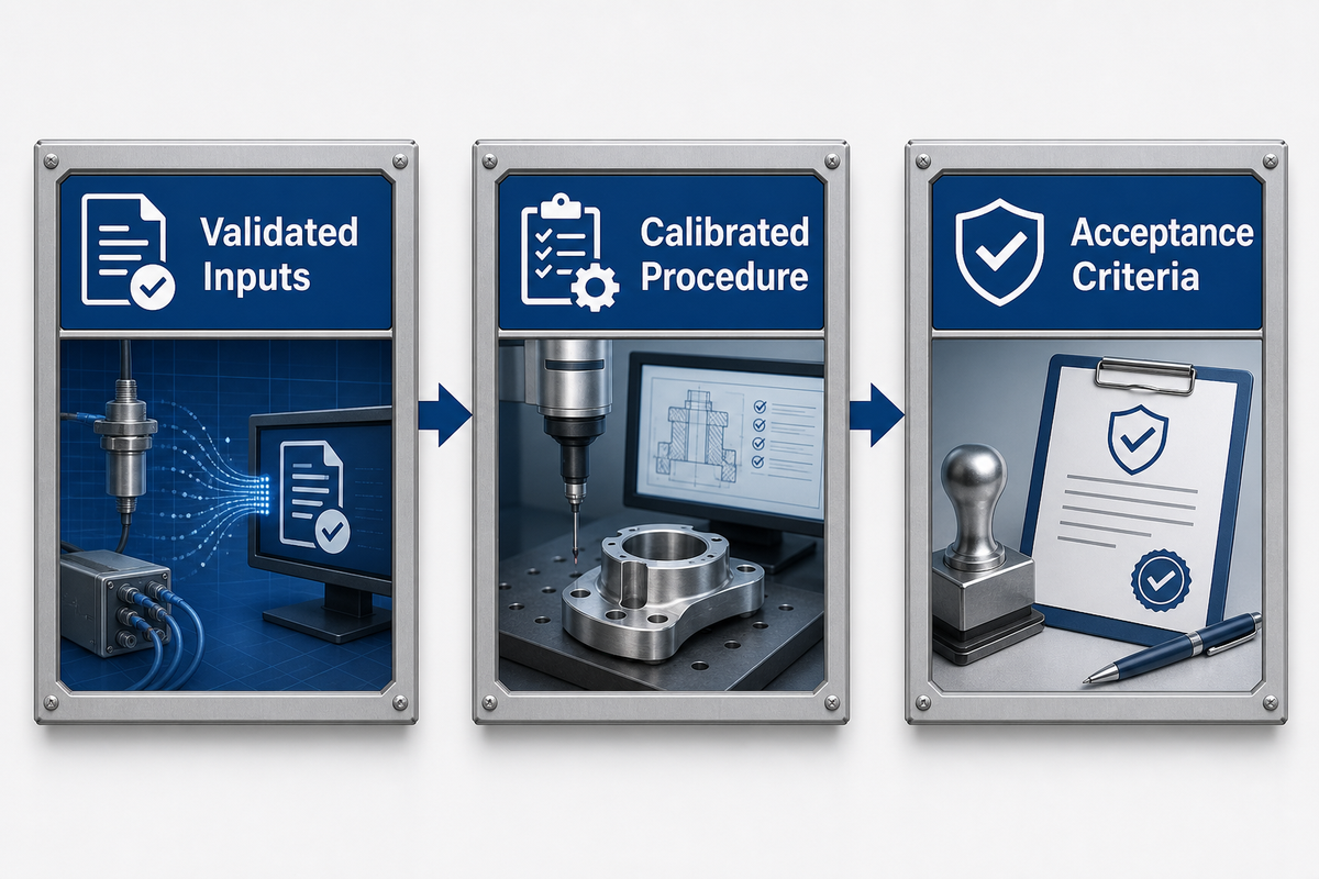
Recent forging-sector signals point toward better process visibility, workforce development, and more structured benchmarking, not the disappearance of engineering judgment. That same buyer-side evidence discipline still applies when automation enters the process. Digital models and adaptive inspection tools can improve consistency, but qualified personnel, calibrated procedures, traceable inputs, and order-specific acceptance criteria still control the meaning of the evidence.
In an April 2025 presentation, the Forging Industry Association reported 41 respondents in Q3 2024 and 30 in Q1 2025. Within that limited association sample, reported revenue increased 5% from 2023 to 2024. Those numbers are useful context, but they are not independently audited market data or a global forecast.
In February 2026, an FIA/FIERF strategy update emphasized benchmarking, certification, workforce development, and modernized technical content. Recent patent disclosures also describe mesh-based flaw prediction and adaptive ultrasonic scanning for forged rings. Patent disclosure shows what someone has documented, not what an industrial supplier has adopted or independently validated.
The buyer-side implication is practical: ask what changed in the evidence package, not whether a supplier uses the word “digital.” A model needs validated inputs. Automated scanning needs suitable geometry, calibration, coverage, and review. Neither removes the distinction between method capability, probability of detection, and the acceptance criteria written into the order.
Conclusion: Learn the Evidence Chain Before Comparing Suppliers
Industrial forging decisions become clearer when 6 questions stay separate: route, material history, metal flow, defect mechanism, inspection coverage, and acceptance basis. Add the 5-link traceability check, and a buyer can review technical evidence without relying on the vague assumption that “forged,” “tested,” or “certified” automatically means suitable.
The article’s core lesson is not that casting or forging always wins. It is that each manufacturing process creates a different evidence problem. For company background, see About China Welong. For supplier-specific capability and drawing support, continue to the linked industrial forgings solution page.
Discuss a drawing-specific forging requirement
Frequently Asked Questions
Is forging always stronger than casting?
No. Forging can align grain flow and reduce some discontinuities when the worked structure follows the service load path. That doesn’t make every forged component superior in every direction, and it doesn’t create a 100% guarantee against defects. Casting may suit internal cavities, integrated shapes, multi-axial loading, or alloys that are difficult to forge. Even a cast or wrought component can outperform a poorly designed forging. Service environment and the specified failure mode still govern the comparison. Compare the actual load case, alloy, heat treatment, section transition, machining plan, inspection coverage, and acceptance criteria rather than ranking the process labels alone.
What is the difference between open-die and closed-die forging?
Open-die forging compresses stock between relatively simple dies while allowing more lateral flow. Closed-die forging drives material into shaped impressions, supporting closer repetition and more complex external geometry at the cost of dedicated tooling. Neither route is universally better. Geometry, quantity, mechanical-property direction, machining allowance, and lead time determine the practical choice.
Which NDT method is best for a steel forging?
There is no single best method. Visual and dimensional checks address shape and surface condition; magnetic-particle testing addresses surface or near-surface indications in ferromagnetic steel; ultrasonic testing addresses internal reflectors; penetrant testing finds surface-breaking discontinuities. Coverage, calibration, flaw orientation, examiner qualification, and the written acceptance level all matter. Complementary methods are often necessary.
What causes laps and cold shuts in forgings?
Laps form when a surface folds over and is worked into the forging. Cold shuts form when converging metal surfaces do not bond adequately because flow, temperature, scale, or filling conditions are unfavorable. They are related to metal flow but are not interchangeable labels. Their relevance depends on depth, orientation, location, and governing acceptance rules.
What should an inspection report identify?
Useful reports should identify the part, drawing revision, heat or lot, quantity, examination stage, written procedure, equipment or calibration basis, personnel qualification scheme, coverage, results, acceptance specification, class or quality level, and disposition. Missing identity links can prevent a technically valid report from proving that the shipped forging meets the specified requirement.
References & Sources
- Forging Industry Association, Product Design Guide for Forging
- Defense Logistics Agency, Forging and Casting Assistance
- ASTM A388/A388M-26, Ultrasonic Examination of Steel Forgings
- ASTM A275/A275M-23, Magnetic Particle Examination of Steel Forgings
- ASTM A966/A966M-15(2025), Magnetic Particle Examination Using Alternating Current
- ISO 9712:2021, Qualification and Certification of NDT Personnel
- Steel Founders’ Society of America, Castings versus Forgings
- FIA/FIERF, Central Burst Prediction in Open-Die Forging, 2024
- FIA/FIERF Joint Strategic Plan, 2026
![Choke & Kill Hose: [Field Guide]](https://welongoiltools.com/wp-content/uploads/2026/07/choke-kill-hose-guide-featured-1-150x150.png)