Get in touch with Welong Company

Quick scope
Industry: oil and gas well construction | Decision: component role, compatibility and evidence package | Updated July 2026 | Not a concrete-finishing tool guide
Cementing Tools are, in this guide, oil-and-gas equipment used around casing, cement placement, displacement, and barrier verification. They do not mean trowels, mixers, masonry saws, or other concrete-finishing tools. That distinction matters because the same search phrase can lead a buyer toward two unrelated product families before the first technical question is even asked.
Cementing Tools should be selected as a connected well-programme package, not as a loose list of part names. Reliable requests link casing and connection data to the planned fluids, pressure and temperature envelope, tool compatibility, supplier verification, and job-specific acceptance path. That produces a clearer technical request without pretending that a catalogue page can design a cement job.
Key points before you compare parts
- Pressure-test records support a decision, but they aren’t universal proof that a cement barrier is adequate.
- Bow-spring centralizers, rigid centralizers, cement baskets, wiper plugs, and cement plugs don’t share one automatic standard scope.
- Ask for supplier verification and operating records as different evidence classes.
Cementing Tools in Oil and Gas: Scope, Purpose, and the Concrete-Tool Trap
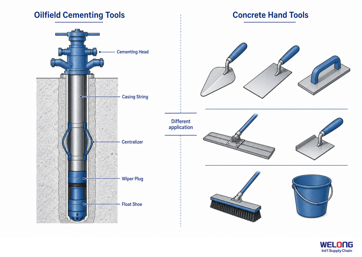
Oil-well cementing tools are part of a casing-and-barrier system. Their purpose is tied to placing and controlling cement in a well context, whereas concrete tools shape, mix, cut, or finish construction material at the surface. Use “oil and gas,” “well,” “casing,” and “zonal isolation” in a request so suppliers, search engines, and project teams are working from the same meaning.
This distinction is more than terminology. For U.S. offshore operations, current 30 CFR 250.428 requires squeeze cementing if a primary cement job hasn’t isolated abnormal pressure intervals before completion, suspension, or abandonment. That jurisdiction-specific example illustrates why oil-well cementing belongs to a casing-and-barrier programme, not a concrete-tool category. No individual component is universal barrier proof.
| If the request says… | It normally belongs to… | First clarifying question |
|---|---|---|
| cementing head, casing, float collar | oil-well cementing equipment | Which well section and casing connection apply? |
| centralizer, stage collar, wiper plug | oil-well tool string / placement plan | What function and evidence are required? |
| trowel, finishing blade, concrete mixer | construction or masonry work | Is this an oil or gas well programme? |
Practical takeaway: Put the well context in the subject line of the request. That wording prevents the common failure of comparing construction-tool results with oilfield equipment before any technical review begins.
On the rig, surface cementing equipment includes the cementing unit used for pumping cement and recording controlled job data; it supports a downhole well programme, not a mechanical, rotary, pneumatic, or diesel engine device used in construction projects.
Material labels such as aluminum, and interface terms such as hopper, gauge, wire, radius, or lift, can appear in an equipment note. None of those labels alone identifies the cementing processes, configuration, or acceptance path.
What Cementing Tools and Equipment Are Used in an Oilfield Cementing Operation?
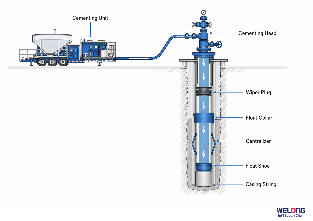
An oilfield cementing operation links surface equipment with a downhole tool string. Surface scope can include a cementing unit, cementing head, pump, mixer, hopper, gauges, and connection hardware; downhole scope can include float equipment, wiper plugs, centralizers, stage tools, and accessories. The U.S. EPA’s casing-hardware reference supports this taxonomy, not a universal specification. Exact lists belong to the programme.
Use the categories below to make a request readable across procurement, operations, and quality review. It deliberately separates a component name from the evidence that confirms its configuration. These are functional request categories, not a current standard or universal purchasing specification; the release questions turn each category into an actionable request.
Surface Cementing Equipment: Cementing Unit, Pump, Mixer, Hopper, and Gauge
Start with the boundary of the surface package. A request may need to state whether the cementing unit scope includes the pump, mixer, hopper, gauge, hose, valve, wire or control connection, as well as any stated pneumatic or diesel engine auxiliary equipment. Recording what is included and excluded prevents a component quotation from being mistaken for a complete surface cementing arrangement.
Downhole Components: Float Equipment, Cement Stinger, Cement Basket, and Packer
For the downhole side, name a component only when the programme makes its location and role relevant. Float equipment, a cement stinger, cement basket, packer, stop collar, wiper plug, centralizer, or stage tool each needs its own configuration and compatibility question; an accessory label is not a substitute for the casing data or intended cementing operation.
| Functional family | Where it belongs in the conversation | Release question |
|---|---|---|
| Cementing head | Surface interface and plug-launch arrangement. | Which casing, line, plug, and verification interfaces must match? |
| Cementing unit | Contractor-defined surface package for the planned cementing process. | What is included in the stated operating and data-record scope? |
| Pump, mixer, and hopper | Surface equipment interfaces when they are in the agreed scope. | Is the request for a component or for a complete surface arrangement? |
| Float shoe and float collar | Downhole float-equipment configuration in the casing string. | What position, flow role, and application evidence are required? |
| Wiper plug | Fluid separation and displacement sequence. | How will launch, seating, and compatibility be confirmed? |
| Centralizer | Casing-placement geometry and the applicable component type. | Which configuration-specific test or drawing applies? |
| Stage tool or stage collar | A multi-stage operation that needs its own programme review. | Which tool, operating plugs, and job assumptions are connected? |
| Cement basket, stop collar, or packer | Accessory scope only when the programme identifies it. | What configuration, location, and evidence package is requested? |
| Cement stinger or diverter | Special interface or routing component when explicitly listed. | What sequence and connection boundary make it relevant? |
Classifying the family first keeps a generic product search from becoming a generic purchase order. Buyers can then move from equipment names to the casing data, operating intent, compatibility check, and release record that each family actually needs in an equipment-supply decision.
Cementing Unit Scope: Connect Mixing, Pumping, and Job Records Before Release
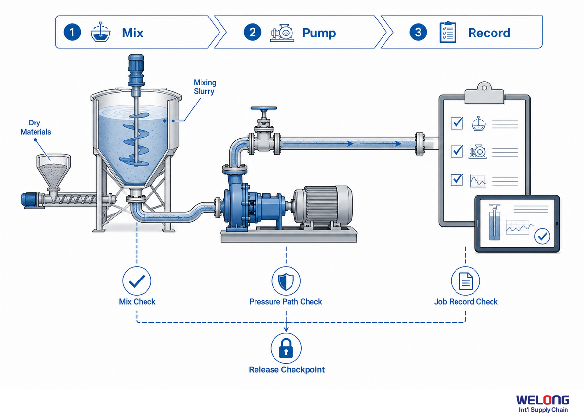
Read a cementing unit as an agreed surface-work scope rather than a single product label. Before a buyer compares a tool or service offer, the request should say which mixing, pumping, line, control, and job-record interfaces are included and who confirms each one. In a BSEE technical review, cementing practices do not transfer unchanged across every operating context, and pre-job engineering is tied to clearly defined objectives. That approach keeps equipment selection connected to the well programme without inventing a universal cementing-unit configuration.
Material, Mixer, and Hopper Scope
At the material-preparation boundary, record whether the request concerns only a downhole component or also a mixer and hopper interface in the cementing unit. State the planned fluid context, the responsible party, and any defined hand-off point. A surface equipment name is useful only when the scope makes clear whether it is supplied, operated, inspected, or simply connected.
Pump, Valve, Hose, and Gauge Scope
For the pumping path, identify the relevant pump interface, valve, hose or rigid line, gauge, and expected data record. API Standard 65 guidance treats job data such as fluid density, rate, surface treating pressure, and additive lot numbers as records that belong in the wider cementing process. Here, those records are used as a prompt to assign ownership and verification, not as a published operating target.
Cementing Operations: Function, Rate, Mud, and Downhole Depth Inputs
For a cementing operation, keep the intended function, relevant rate, fluid or mud context, and downhole depth within the programme record rather than attaching bare numbers to a product request. Casing position, borehole conditions, liner or zone objective, circulation path, hydrostatic-pressure assumptions, and any workover boundary can change which surface and downhole components need review.
Working unit-scope check: Before release, assign an owner for each open item.
- Surface package included or excluded
- Connection and treating-line boundary
- Mixing and pumping responsibility
- Gauge and job-data record
- Tool-string compatibility and acceptance path
Cementing Heads and Surface Interfaces: A Late-Step Control Point in the Cementing Sequence
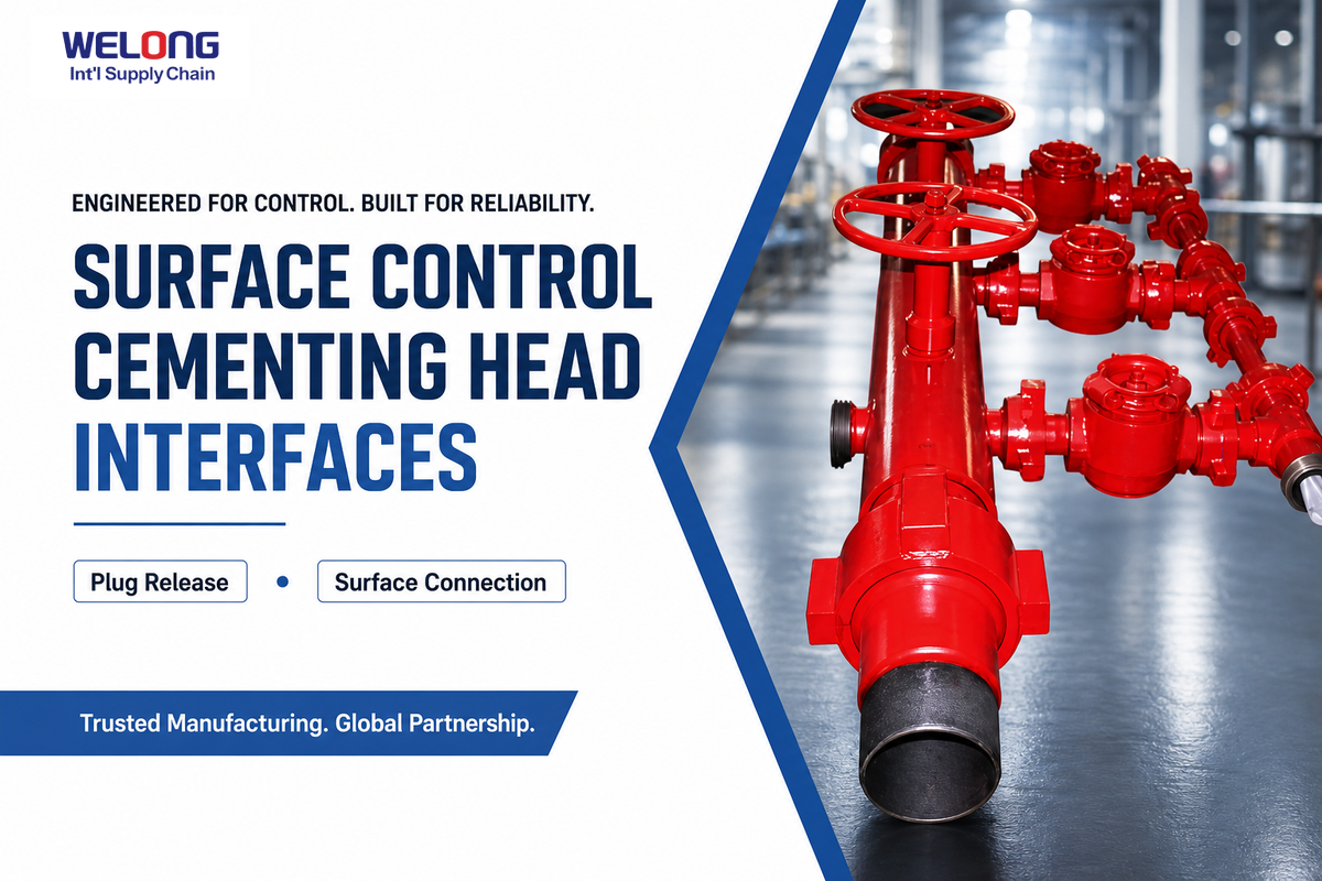
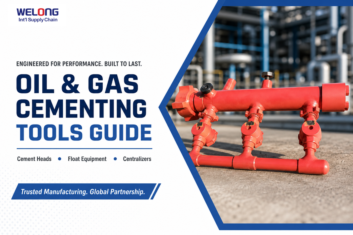
Cementing heads are surface control points in the execution sequence: they manage the interface at the top of the casing and can organise plug release. That point is not where the cementing design begins. In offshore oil-and-gas work, an unresolved interface is a job risk because it can delay the intended displacement sequence. Wellbore preparation, fluid design, displacement modelling, connection planning, and contingency review should already be defined before the head is treated as ready for use.
That sequence changes the questions a buyer should ask. Instead of asking only for a “cementing head,” ask how the temporary treating line, hose or rigid connection, casing connection, pump interface, plug-container arrangement, rated working-pressure information, and pressure-test record relate to the actual programme. The BSEE technical review similarly calls for pre-job engineering and simulation tied to defined objectives; API RP 54 addresses pressure-line safety in this operating environment, while API Standard 65 guidance places cementing-head activity within a wider communication, design, and execution process.
“A pressure-capable surface interface is only one control point. It cannot replace the programme inputs that determine whether the connection, fluid path, plug sequence, and contingency plan fit the well.”
Editorial interpretation of API RP 54 and API Standard 65 guidance
Scenario: When a buyer receives a cementing-head quotation with a connection size but no plug-launch description, line arrangement, or test-record expectation, missing detail is not solved by selecting a higher published rating. Reconciliation of the casing connection, planned plug sequence, line configuration, and applicable verification record with the job team is the correct next move.
Risk check: In an offshore oil-and-gas programme, an incomplete interface definition can delay the job or break the intended displacement sequence. Treat the missing input as an open technical risk, not as a reason to select a higher catalogue rating.
Surface Cementing Equipment and Cementing-Unit Interfaces to Clarify
The cementing unit is the surface package that connects the pumping-cement process to the casing-side execution path. In a contractor’s actual layout, the package may involve a pump, mixer, hopper, gauge, valve, hose, wire, or control connection and, where specified, a pneumatic or diesel-engine drive. Those labels help scope a request; they do not establish a universal configuration, operating rate, pressure limit, or acceptance standard.
| Interface prompt | What the request should state | What it does not settle |
|---|---|---|
| Casing and connection | Casing section, connection path, and the party that confirms the interface. | Whether the whole cementing programme is ready. |
| Pump and fluid path | The relevant pump interface, treating line, hose or rigid connection, and record expected. | No universal rate or pressure limit. |
| Mixer and hopper | Whether the cementing unit scope includes slurry-preparation interfaces or only a tool-string component. | The final fluid design. |
| Gauge and job record | Which gauge or data record is needed, who owns it, and when it is reviewed. | Barrier acceptance by itself. |
| Valve, hose, and wire controls | The connection boundary and any stated control or release responsibility. | Compatibility with every plug or tool arrangement. |
| Drive and auxiliary equipment | Whether pneumatic or diesel-engine equipment is part of the contractor’s stated layout. | A required drive type for all cementing operations. |
| Cement stinger or diverter | Whether either item is actually listed and how it connects to the defined sequence. | That it is needed in every well. |
Keep this schedule separate from product selection. It gives procurement, operations, and quality teams one way to turn broad terms such as cementing equipment or cementing operations into open questions that can be assigned before release.
Practical takeaway: Treat a cementing head as an interface that must fit an already-defined execution plan. Never treat the head’s catalogue description as a substitute for that plan.
Float Shoes, Float Collars, and Flow Direction in the Casing String
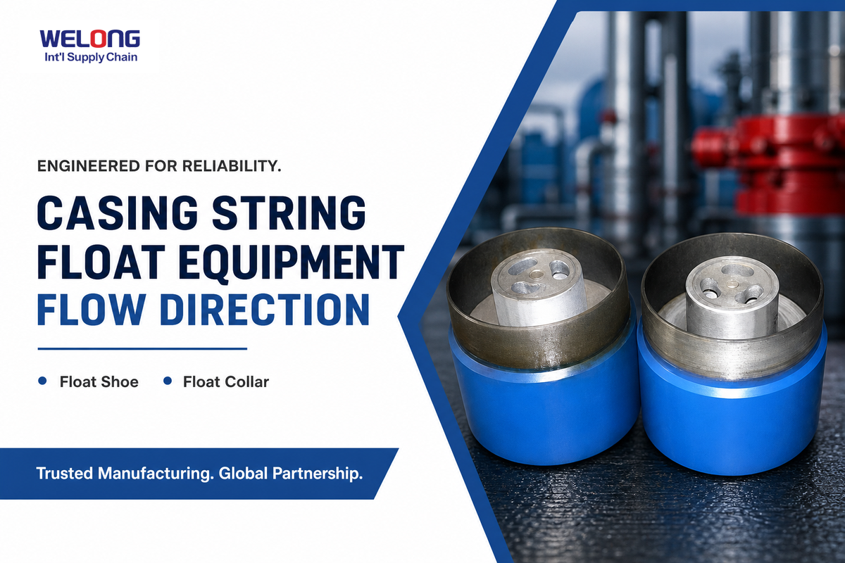
Float shoes and float collars should be identified by location, intended flow-control role, connection, and compatibility—not grouped under a generic “float equipment” label. The U.S. EPA’s casing-hardware material includes float equipment among the components considered in oil-well cementing; string position and the way selected components interact with plugs, fluids, and the planned displacement sequence change what must be checked before release.
API Standard 65 guidance makes the central point clearly: float equipment has application-specific pressure and temperature ratings, and not every wiper-plug or operating system is compatible with every float-equipment or stage-tool arrangement. For bow-spring centralizers, the related performance vocabulary can include starting force, running force, restoring force, and 67% standoff in a defined test context. Those are test and application terms, not interchangeable specifications for every casing string.
An effective float-equipment request therefore names the casing OD and weight, connection, intended position, anticipated fluids, pressure and temperature envelope, plug arrangement, and the supplier evidence expected for the selected configuration. “Float shoe” and “float collar” are the start of the discussion, not the end of it.
In a borehole with a liner across a defined formation or zone, state depth, mud, circulation path, hydrostatic pressure, high-pressure limit, and whether a weak interval changes the seal objective.
Common mistake: Treating a second valve or a familiar component name as proof of suitability. Familiar components can still be incompatible with the selected plugs, drilling fluid, connection, or intended operating sequence.
Practical takeaway: Specify the position and function first, then ask for configuration-specific compatibility and supplier verification.
Wiper Plugs, Cement Plugs, and Tool-String Intent
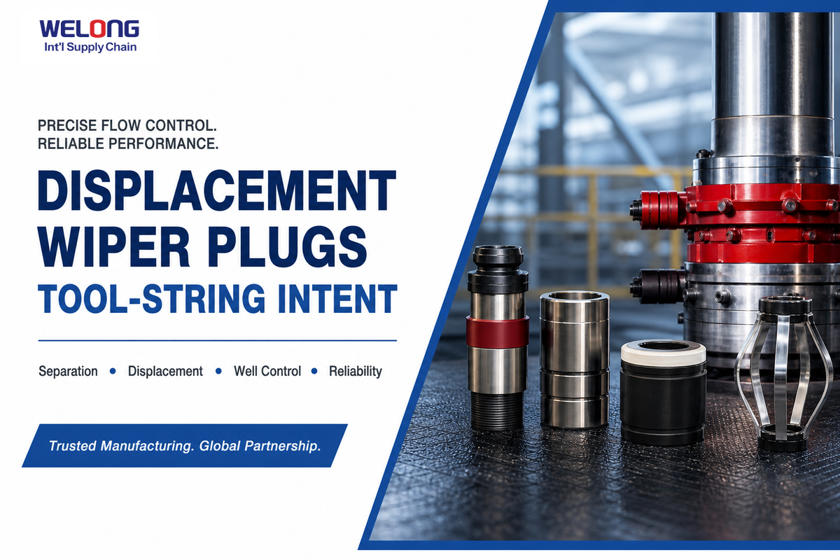
Wiper plugs used during primary cementing and cement plugs used in remedial, closure, or barrier contexts should not be treated as the same procurement decision. Each wiper plug belongs to a planned displacement sequence. Cement plugs for remediation or permanent or temporary closure can involve a broader design, placement, and verification question.
For primary cementing, the buyer needs to understand how a cement wiper plug, plug container, float equipment, and casing string are meant to work together. Key evidence is compatibility, launch method, seating expectation, and the record that identifies the actual configuration. This is not a request for a generic “plug for cementing.”
For remedial work, plugging and abandonment, or annular-barrier work, the term “cement plug” can point to a different intent. In one jurisdiction-bounded example, 30 CFR 250.428 requires squeeze cementing when a primary cement job fails to isolate abnormal-pressure intervals before specified U.S. offshore operations continue. The safe procurement habit is to state whether the request is for primary cementing, a remedial operation, temporary closure, permanent closure, or another verified barrier objective. A mismatch in intent is a preventable risk because the accepted operating sequence and evidence path can change with the scope.
Scenario: Two requests each say “cement plug.” One is a casing-string request for a primary job; the other concerns a closure barrier. Although the names look similar, the decision inputs, operating sequence, acceptance criteria, and governing guidance may differ. Each RFQ should make the intent visible before a supplier selects a component family.
Practical takeaway: Write the plug’s operating intent into the request. That one sentence can prevent a primary-cementing sequence from being confused with a remedial or closure-barrier scope.
Centralizers and Accessories: Protecting Placement Geometry Without Overstating Standard Scope
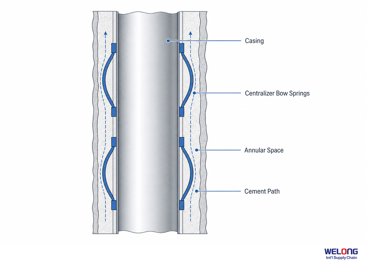
Centralizers are used to support casing placement geometry, but appropriate evidence is specific to the centralizer type and the condition of installation. Don’t assume a bow-spring centralizer report applies to a rigid centralizer, cement basket or other accessory; request the appropriate test method, configuration and report scope.
ISO 10427-1:2024 applies to bow-spring centralizers but isn’t a standard for rigid centralizers or cement baskets. This boundary can inform technical requests and help the buyer know what questions to ask regarding the offered product family, any test conditions (install or holding), and whether the test record pertains to the delivered component configuration.
| Component category | Decision input | Evidence to request | Do not assume |
|---|---|---|---|
| bow-spring centralizer | casing, hole condition, installation | applicable performance report and test scope | that it covers rigid types |
| rigid centralizer | geometry, clearance, connection | configuration-specific drawing and verification | that bow-spring results transfer |
| stop collar | position retention and interface | applicable holding/test evidence | that marking alone proves performance |
| cement basket | loss-risk context and programme intent | design basis and compatibility review | that centralizer scope applies |
| scratcher | movement mode and casing programme | fit, attachment, and operating limitation | that it corrects every hole condition |
| external casing packer | barrier objective and stage architecture | job-specific engineering review | that it is a drop-in accessory |
| guide shoe | casing route and leading-edge need | dimensions, connection, drill-out expectation | that every shoe has float function |
| float shoe | flow-control role and tool-string location | compatibility and applicable rating evidence | that it replaces a collar decision |
| stage collar | stage plan, ports, plugs, contingencies | design/compatibility documentation | that a standard list is sufficient |
Reading a type-qualified centralizer record: A published bow-spring centralizer reference can report a 3-inch (89 mm) sample yielding 396 lbf at 67% standoff and an 8-inch (219 mm) sample with 1,440 lbf under the same documented condition, or even a 20-inch (508 mm) sample producing 1,880 lbf. Such records can state 1.6 mm (1/16 in) test-position increments with 5% measurement accuracy. These details define a complete record but do not create transfer rules or target specifications for rigid centralizers, cement baskets, alternative casing programmes, or other test setups.
| Record field | Published bow-spring illustration | Buyer verification question |
|---|---|---|
| sample dimensions | 3½ in / 89 mm; 8⅝ in / 219 mm; 20 in / 508 mm | Does this identify the same supplied centralizer type and casing programme? |
| reported restoring force | 396 lbf; 1,440 lbf; 1,880 lbf | What test arrangement and holding condition produced the figures? |
| standoff condition | 67% stated standoff | Is the stated condition applicable to the proposed geometry? |
| test-position increment | 1.6 mm / 1/16 in increments | Can an independent reviewer trace the result to the documented method? |
| measurement statement | 0.8 mm / 1/32 in reference; 5% accuracy | Does the report state its measurement boundary rather than implying universal precision? |
Retain the source units of force measurement in a record’s audit trail, for example, connecting 3 inches / 89 mm to 396 lbf and 8 inches / 219 mm to 1,440 lbf at the documented 67% standoff condition, and similarly associating 20 inches / 508 mm to 1,880 lbf. Apply the same care with a 1.6 mm test step and the stated 5% accuracy constraint. Recoding a value without specifying the component class, test orientation, and standoff condition will make otherwise valid records hard to interpret.
Configuration values are indicators, not design instructions: A published cementing-head configuration could list coverage of 5 inches (139.7 mm) versus 13 inches (339.7 mm) casing, 35 MPa vs. 50 MPa working pressure classes, or pressure references of 5,000 psi, 7,250 psi, and 10,000 psi, and identify a 2-inch union connection. Such specifications are useful in specifying the RFQ and verifying components but don’t indicate a correct setting, confirm a job design, or substitute for the well team’s decision to accept or reject.
Practical Takeaway: Ask for the evidence to support the component and install method rather than applying a general compliance statement across all accessories.
Stage Cementing and Remedial Scenarios: When a Standard Tool List Is Not Enough
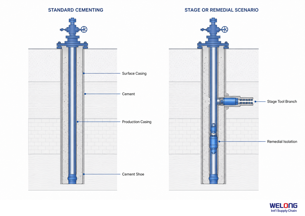
Stage cementing and remedial work need a separate design review whenever a simple single-stage tool list cannot represent the operating objective. Review component specifications alongside the supporting simulation, cement properties, pass-through geometry, compatibility with other casing equipment, potential failure modes, and contingency plan.
That distinction appears in API RP 10G’s treatment of stage-cementing collars: selection of the collar and operating plugs is separate from job procedures and their underlying engineering. A tool-stage description alone does not establish adequacy. The decision becomes more complex when a proposed stage tool differs from a standard primary-cementing job in pressure constraints, loss risk, interval objective, remedial scope, or target barrier.
A BSEE summary of U.S. Outer Continental Shelf practice makes a similar point: few cementing practices apply across every condition. Job objectives therefore need meaningful links to engineering design and simulations. This is a U.S. offshore operating practice, not an alternative to the specific requirements of another well.
Current documentation is another part of the tool requirement. Although ISO 10427-1:2024 and other standards can frame applicable questions, an older citation should not simply be copied into an RFQ. The project team should determine the current API, ISO, operator, and jurisdictional requirements for the programme.
When a cement stinger, diverter, or workover requirement changes the tool string or cementing process, the supplier should identify how the configuration fits the planned placement sequence before manufacture.
Escalation threshold: Stop considering tool requests as simply product list comparison and ask for engineering review if a specified stage or remedial tool can’t be correlated with a defined operating objective, compatible tool string, pass-through geometry, pressure/temperature envelope, and contingency path.
What to do next: A stage tool is not a default upgrade; it is an engineering decision that requires the component evidence and programme to align.
The 8-Point Cementing Tool String Readiness Map
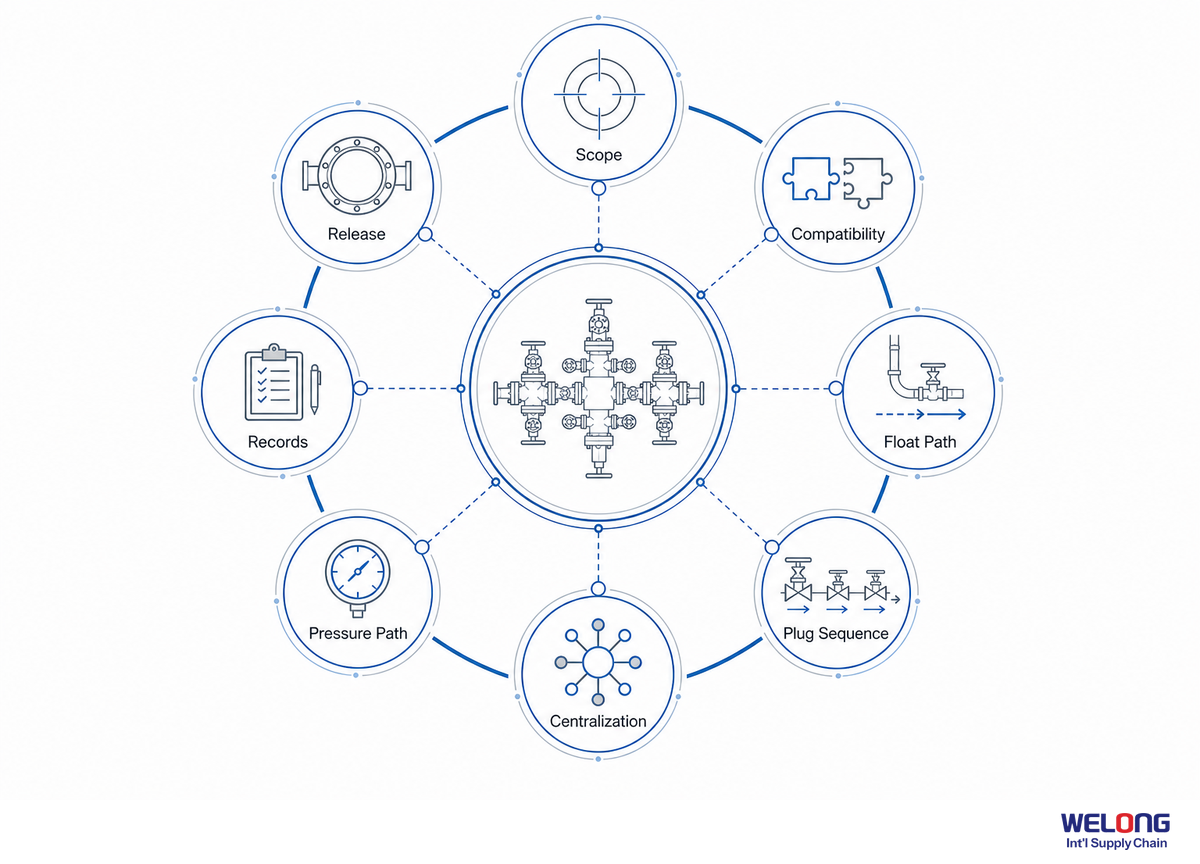
The 8-Point Cementing Tool String Readiness Map is a buyer framework that moves from a component list to eight connected inputs for comparative review. It is not a tool-design calculation, product certificate, or substitute for the actual cementing programme. Instead, it identifies the information a supplier needs to verify configuration and evidence. The discipline aligns with a BSEE technical review: define job objectives before applying cementing practices rather than treating a generic tool list as self-sufficient.
- Casing definition: section, OD, weight, and relevant string position.
- Connection path — the casing connection’s interface with surface equipment and any temporary treating-line interfaces.
- Pressure envelope — anticipated job conditions used when comparing relevant equipment evidence.
- Temperature and fluid context — job-specific ambient conditions and fluids for comparison, not generic catalogue terms.
- Operating intent — primary cementing, multi-stage work, remedial action, well closure, or another defined barrier purpose.
- Tool-string compatibility — float equipment, plug system, centralizer or accessory type, and tool interfaces between stages.
- Supplier verification — component dimensions, an itemised delivery schedule, applicable design or test specifications, marking or traceability where needed, and confirmation of the component configuration.
- Job and acceptance records — actual job data, specified functional or inspection records, and the path for regulatory or operator acceptance.
Two evidence lanes prevent an avoidable RFQ gap
Point 7 and Point 8 separate two evidence lanes. The supplier-verification lane asks, “Is the proposed item what the buyer requested?” It may include schedule lines, dimensional data or drawings, connection identification, marking or traceability where specified, and the scope of any required design or functional verification record.
The job-and-acceptance lane asks, “How will the operator, service provider, or relevant authority determine whether the installed product meets the programme?” Depending on the task, the answer can involve prescribed procedures, monitored job data, functional or integrity tests, acceptance criteria, exception handling, and required approvals. A product document cannot answer that full question, and a job record alone cannot confirm that the supplier delivered the ordered configuration.
This separation helps buyers coordinate procurement and operational requirements across multiple teams. The purchasing team can close the configuration and evidence package before shipment, while the project team owns the well-specific execution and acceptance trail. That creates a usable handoff instead of burying requirements inside an undefined request for “all certificates.”
Hidden Bottleneck Map: the system can stall not because a supplier cannot name the component, but because one of the eight inputs remains unknown. An unconfirmed interface can prevent approval; unclear plug intent can delay compatibility review; and unclear evidence scope can leave technical feasibility established but delivery unapproved.
For buyers ready for a commercial handoff after programme definition, China Welong’s custom cementing-tool solutions for a defined well programme page is the next step. It carries approved inputs into a supplier discussion; this guide clarifies what those inputs can look like.
Practical implication: Do not assume or leave blank any field on the map. Label it an “Open Technical Question.”
At tender stage, define the cementing equipment package, well section, casing string, cement slurry, and displacement sequence together so operations and procurement are working from the same request.
The Cementing Tool-to-Barrier Decision Matrix
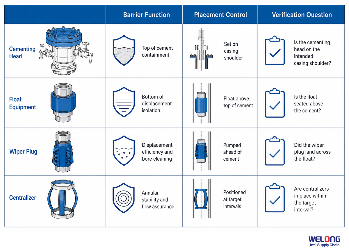
The Cementing Tool-to-Barrier Decision Matrix associates a component family with its decision question, supplier check, work documentation, and the part of the decision that documentation cannot answer. It helps a buyer avoid a common documentation mistake: treating a product document, pressure test, or cement-evaluation artifact as a standalone acceptance decision outside the agreed programme.
A bounded U.S. offshore example appears in 30 CFR 250.428: identification of inadequate cement can require additional evaluation or remedial work, and continued operations can require approval. BSEE also treats a passed pressure test as a condition, not a guarantee of a sufficient verification regime. Other jurisdictions and operator programmes differ, so use this reasoning rather than applying a blanket acceptance mandate.
| Tool / record | Barrier question | Supplier verification | Job evidence | What it does not prove alone |
|---|---|---|---|---|
| cementing head | Does the surface interface fit the execution path? | configuration, connection, pressure-test record | line-up and operating plan | cement placement adequacy |
| float shoe | Is leading-end flow control defined? | configuration and applicable rating evidence | string position and fluid context | whole-string compatibility |
| float collar | Is the planned collar role clear? | connection and compatibility confirmation | placement sequence | that a shoe decision is unnecessary |
| wiper plug | Can the displacement sequence be executed as planned? | plug/container compatibility | launch and displacement record | closure-barrier adequacy |
| cement plug | What barrier or remedial intent applies? | defined component scope | design, placement, verification path | wiper-plug equivalence |
| bow-spring centralizer | Is the stated geometry evidence applicable? | test/report scope and installation condition | centralization plan | rigid-centralizer suitability |
| rigid centralizer / accessory | Does this type fit the defined geometry? | drawing and applicable verification | programme-specific placement review | bow-spring test transferability |
| stage collar | Can the stage architecture be executed? | tool and operating-plug compatibility | simulation, procedure, contingency review | single-stage equivalence |
| job-data / evaluation record | Does evidence support the agreed acceptance path? | record format and item traceability | operator criteria and applicable review | universal barrier proof |
API Standard 65 also differentiates recorded quantities and live job data from engineering judgement of the result. This is why the matrix has two evidence columns: the first asks whether the supplied component matches what was requested, while the second asks whether job evidence supports the programme and acceptance criteria.
Practical takeaway: A complete release package is not the largest stack of papers. It is the smallest set of records that lets the buyer connect the supplied configuration to the contracted job and acceptance path without guesswork.
What Is Changing in Cementing Tools—and What Buyers Should Watch
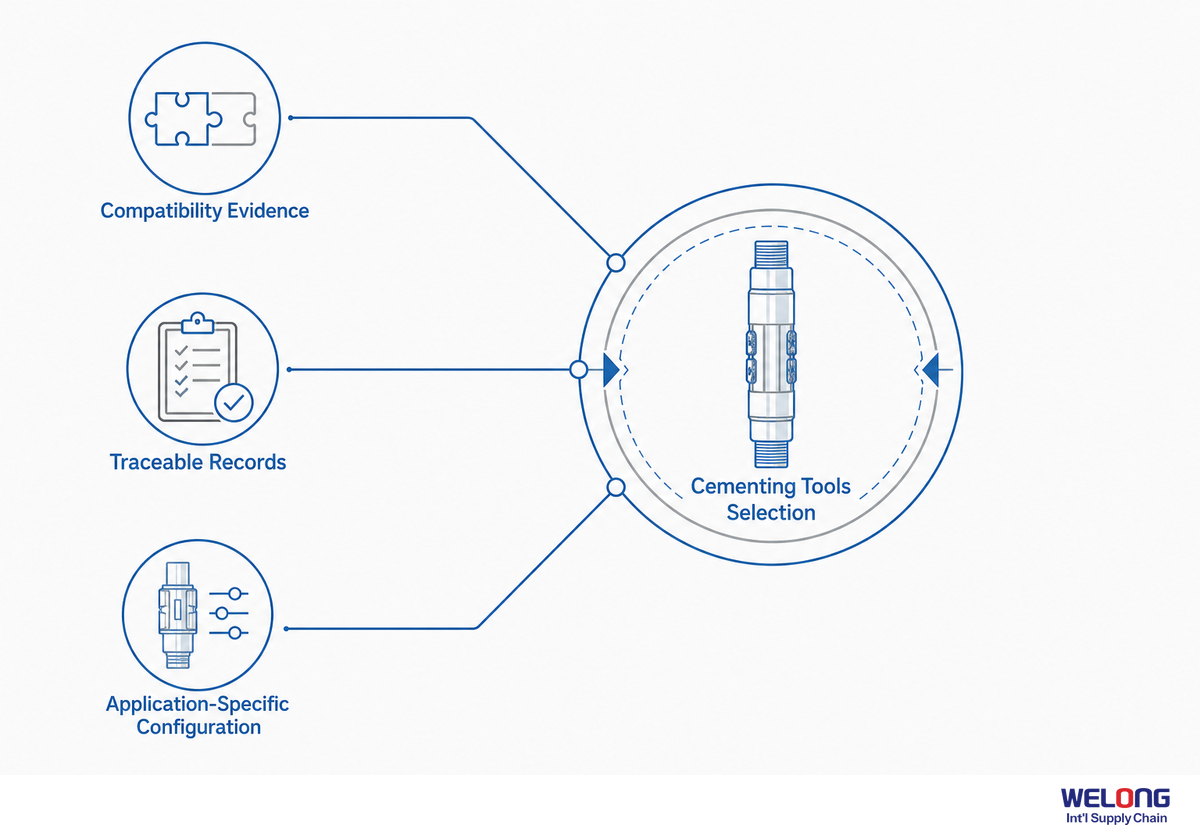
For cementing-tool buyers, the useful trend is not a generic growth forecast but the need to keep configuration, verification, and job data connected as programmes become more complex. The BSEE technical review notes that practices do not transfer unchanged across every U.S. Outer Continental Shelf context. For stage work, remediation, plugging and abandonment, or digital records, write those requirements into the initial technical request.
A 2026 scholarly review of intelligent drilling and completion includes intelligent cementing operations in its forward-looking scope. Where digital monitoring or data acquisition is part of an offshore oil-and-gas programme, establish which data are needed, who owns the record, and how it connects to the acceptance process. A digital dashboard does not remove the need for compatible equipment, defined operating intent, or qualified interpretation.
Standards are another moving part. API maintains an announcements channel for updates, and ISO documents have specific publication dates and scopes. Build a revision check into the RFQ instead of copying a standard number from an old document. A late revision gap can create a preventable specification risk, particularly when the project has already selected a tool family.
Practical takeaway: For the next programme, make “current applicable requirement and evidence owner” a line item alongside the tool schedule. It is a small prompt that can expose a late technical gap before it reaches the wellsite.
Frequently Asked Questions
Are cementing tools the same as concrete cement tools?
View answer
No. In this guide, cementing tools are oil-and-gas well equipment used with casing, cement placement, displacement, and barrier verification. Concrete finishing tools, masonry mixers, trowels, and saws belong to construction work. Include the oil-and-gas well context, casing section, and operating intent in the request so the intended product family is clear before anyone compares a tool name or catalogue image.
What information should be prepared before requesting cementing tools?
View answer
Prepare the casing section, connection, anticipated pressure and temperature conditions, fluid context, operating intent, tool-string interfaces, supplier-verification expectation, and job/acceptance-record expectation. Identify the person who owns each open input and state whether the work is primary cementing, multi-stage, remedial, temporary closure, permanent closure, or another defined barrier scope. That separates a quote request from a usable technical request.
What are the components of a cementing unit?
View answer
A cementing unit is a programme-defined surface package. Depending on the agreed scope, it may involve a pump, mixer, hopper, gauges, valves, hoses, controls, data-record interfaces, and auxiliary equipment, while the cementing head and downhole tool string remain connected but distinct decisions. Ask which interfaces are included, who owns the records, and which casing and plug arrangement they must fit before treating the description as a complete equipment scope.
Why should float shoes and float collars be specified separately?
View answer
They occupy different positions and can have different roles within the casing string. The request should identify intended location, connection, plug-system compatibility, fluid context, and the configuration-specific evidence required. It should also say what the component must interface with before and after the displacement sequence. A broad “float equipment” label doesn’t answer those questions or confirm compatibility.
What should be checked beyond a cementing-tool price?
View answer
Compare price only after the configuration is defined. Check dimensions, connections, component compatibility, agreed inspection or functional-test scope, marking or traceability where applicable, and packing identification. Then separate the supplier’s product-verification documents from the job records required by the well programme. A low price can’t resolve a missing connection definition, a mismatched plug arrangement, or an untraceable test scope; those gaps should be visible before commercial comparison begins.
When should a buyer request a stage-cementing review?
View answer
Request a review when a single-stage tool list doesn’t capture the operating objective, interval conditions, pass-through geometry, plug compatibility, pressure/temperature envelope, potential failure modes, or contingency path. Before the supplier quotes a stage route, ask the operator or cementing engineer to identify the configuration-specific interfaces, evidence expectations, and contingency path if the planned sequence changes. Stage cementing is a programme decision, not a generic upgrade.
Which documents matter most at cementing-tool release?
View answer
The right document set depends on the agreed scope. It can include an itemized tool schedule, dimensional and connection confirmation, marking or traceability evidence where applicable, configuration-specific test or design-verification records, inspection/functional evidence when specified, and the job/acceptance record path. Treat each item as a separate evidence category with a document owner, revision or date, and acceptance status. That helps the buyer see whether a record supports the supplied configuration, the specified inspection scope, or the planned job sequence. A generic certificate should not be treated as proof of every conclusion at once. Where a scope boundary remains open, the release list should name the unanswered question rather than imply that it is closed. This gives purchasing, field operations, and the supplier the same record of what still needs confirmation before release. The operator, engineering review, and applicable acceptance process determine what completes the release package.
A transparent note on this guide
This article is an editorial framework based on publicly available government, standards, academic, and industry sources. The operator’s cementing programme, engineering review, current applicable requirements, vendor data sheets, and any jurisdiction-specific acceptance process supersede this framework.
References & Sources
- Cement Fatigue and HPHT Well IntegrityU.S. Bureau of Safety and Environmental Enforcement.
- API Standard 65 guidanceAmerican Petroleum Institute.
- API RP 54American Petroleum Institute.
- 30 CFR 250.428Electronic Code of Federal Regulations, U.S. Government.
- ISO 10427-1:2024International Organization for Standardization.
- Analysis of Current Cementing Procedures Employed in the U.S. Outer Continental ShelfU.S. Bureau of Safety and Environmental Enforcement (2013).
- API Standards News HighlightsAmerican Petroleum Institute.
- Intelligent drilling and completion technology reviewScienceOpen.
![Choke & Kill Hose: [Field Guide]](https://welongoiltools.com/wp-content/uploads/2026/07/choke-kill-hose-guide-featured-1-150x150.png)