Get in touch with Welong Company

![Casing, Tubing & Drill Pipe Elevators [Field Guide]](https://welongoiltools.com/wp-content/uploads/2026/09/casing-tubing-drill-pipe-elevators-guide-featured.png)
Oilfield handling field guide · Updated September 2026
Comprehend the load path, match the support mechanism, verify 4 critical interfaces and maintain evidence of inspection accessible throughout the pre-use assessment and controlled disposition.
In short: select a pipe elevator by following the load path. Confirm the tubular’s load-bearing feature, the bore or inserts, complete closure, the link or bail interface, and traceable identity and rating evidence. Rated capacity is necessary, but it is not proof of fit.
Casing, Tubing & Drill Pipe Elevators are load-bearing handling tools in the hoisting systems of drilling rigs. By itself, a tool catalog number only identifies the tool designed to handle a particular load. It cannot confirm that the tubular on the floor, the fitted bore or inserts, the latch, and the link interface all match today’s operation.
This field guide has a distinct role from Welong’s casing, tubing and drill pipe elevator solution page. The Page controls product families, model-level specifications, and the commercial offering. This article covers the educational work that precedes a product comparison: identifying the support structure, understanding the closure design, preparing pre-use assessment evidence, and deciding when an unresolved mismatch requires the selection to stop for technical review.
Scope and safety: this is a decision and inspection framework, not an operating procedure, engineering approval or replacement for the applicable standard, manufacturer manual, employer program, lifting plan or competent-person judgment. Don’t assume a wear limit, proof-test interval or a repair strategy is provided in a general article.
1 · Identify
Tubular, profile, operation and tool identity
Tubular, profile, operation and tool identity
2 · Match
Support feature, bore or inserts and closure
Support feature, bore or inserts and closure
3 · Verify
Links, retention, rating evidence and condition
Links, retention, rating evidence and condition
4 · Control
Lift sequence, records and disposition
Lift sequence, records and disposition
1. What a Pipe Elevator Does in the Rig Hoisting System
A pipe elevator isn’t just a clamp. It’s a load-bearing interface in a system. These elevators surround or engage a tubular, transfer the suspended tubular’s weight to the elevator body, and transmit the load through links or bails to the hook or top drive system. Load transfer begins at the tubular’s compatible support feature, continues through the elevator’s closed body, and reaches the hoisting equipment through the matched links or bails. The official API composite-list taxonomy places casing, tubing, drill-pipe and drill-collar elevators among links, hooks, adapters and other hoisting elements under API 8C categories. This component list makes one point clear: an elevator does not operate in isolation.
The two-page public preview of API Recommended Practice 8B also includes casing, tubing, drill-pipe and drill-collar elevators in the hoisting equipment it describes. The preview says the document addresses inspection, maintenance, repair and remanufacture of equipment made to API 8A, API 8C or ISO 13535 for drilling and production operations. Because that preview shows scope and contents rather than the complete requirements, authority remains with the applicable purchased standard and controlled procedures.
The Load-Path Before Load-Rating Rule
Trace the position where the tubular is supported. Then, determine how the closed elevator passes load to the links. Only after those interfaces are correct should rated capacity become an acceptance check. More load capacity can’t make up for a wrong shoulder, an incorrect insert, incomplete latch engagement or an incompatible link eye.
That rule also prevents a common language error. Elevator can refer to different mechanisms, duties and levels of complexity. For example, a mechanism designed to move and position just one joint doesn’t automatically do the same work as a string elevator, which is why single joint elevators, tubing elevators, and manual elevators must be checked against the stated duty. Likewise, a center-latch body does not tell you whether the load is carried by a square shoulder, a taper or slips; center latch elevators and center-latch elevators are spelling variants for closure architecture, not proof of the support mechanism. When selecting a closure architecture and support mechanism, ensure they remain as separate lines in the selection record.
2. Casing vs. Tubing vs. Drill Pipe Elevators: Match the Tubular First
When recording, always begin with the tubular and the operation rather than the tool name, even when a drilling manual or handling tools catalog starts with a family label. General names won’t protect you in situations where a drawing revision, premium connection or special upset change the profile of the mechanism; this matters in drill string or casing running work involving heavy casing, special casing, or adjacent running tools. Record the tubular type, nominal outside diameter, actual load-bearing profile, connection or coupling geometry, upset or taper where relevant, and whether the task involves one joint or a suspended string. The published range of steel pipe and OCTG products from Synbase Steel can help identify the tubular product family, but elevator compatibility still requires the exact drawing and approved handling configuration.
| Duty | Record before selection | What must not be assumed |
|---|---|---|
| Casing | Body OD, coupling or shoulder profile, string duty, handling sequence | That nominal OD proves coupling clearance or support fit |
| Tubing | OD, upset/coupling detail, workover or production-handling duty | That a casing-style label covers the tubing connection |
| Drill pipe | Pipe body, tool-joint OD and load shoulder or taper | That pipe-body OD defines the supporting bore |
| Drill collar | Collar OD, shoulder geometry and handling configuration | That a drill-pipe tool is interchangeable |
| Single joint | Individual-joint duty, pickup method and compatible profile | That light handling duty authorizes string suspension |
For operations involving drill pipe, refer to the drill pipe guide to clarify body and tool-joint terminology for the elevator interface. For a collar-heavy bottomhole assembly, the drill collar guide will provide the context of the adjacent component. These references clarify tubulars; they don’t approve an elevator pairing.
3. Shoulder, 18° Bottleneck, and Slip Support Mechanisms
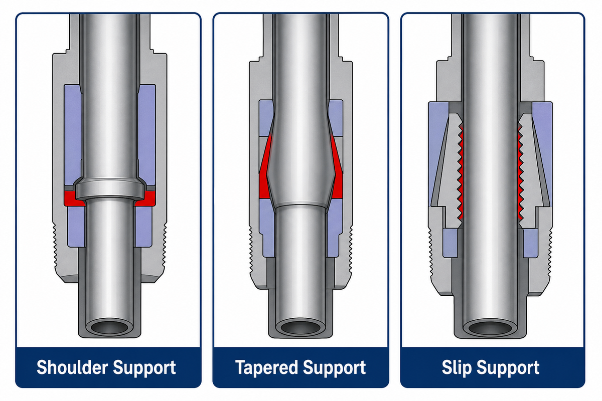
The useful classification question is: What does the suspended load rest on?
Field rule: A drill pipe elevator specification, side door elevator manual, or slip type elevators brochure is only a starting point. Match the exact tubular profile, support feature, closure, and link interface before treating any listed capacity as usable.
With a collar- or square-shoulder design, the load rests on a matching, enlarged feature. In a bottleneck design, the load bears on a matching tapered upset. Slip-type designs use inserts or slips to engage the pipe body. These descriptions provide the basis for load transfer; they don’t mean that all manufacturers have the same geometry or naming, and related labels such as spider, casing spiders, or rotary holding equipment must not be treated as interchangeable elevator functions.
| Support mechanism | Load-bearing feature | Key verification question |
|---|---|---|
| Square shoulder / collar supported | Compatible shoulder, coupling or collar surface | Does the elevator fully seat on the intended supporting surface without interference? |
| 18° bottleneck / tapered | Matching external upset or tapered load shoulder | Are taper, bore and contact pattern the approved combination? |
| Slip type | Pipe body through fitted slips or inserts | Are the correct inserts installed, seated, in condition and approved for the body? |
The hidden failure in many selection conversations is treating size as one number. The pipe body, tool joint or coupling, bore in the elevator, installed inserts, and clearance, can all be dimensions of interest; for 18° type elevators, that includes confirming the specified 18° external upset as the intended bearing profile. In controlled documents, distinguish the support mechanism for drill pipe from the closure mechanism for drill pipe elevators: a collar type or 18° label still must identify the approved bearing feature and whether the tool is expected to support the weight of the entire string. Record the actual profile and the manufacturer’s approved combination. If the support surface is unresolved, a higher capacity rating does not make the pairing acceptable.
4. Center-Latch and Side-Door Elevators: Closing Is Part of the Load Path
Center-latch and side-door describe the body’s opening and closing mechanism. They don’t directly explain how the tubular is supported. Whatever the design, inspection has to follow the closing path: body and hinge condition, free movement, latch or pawl engagement, the safety latch or other secondary retaining feature specified by the manufacturer, and the approved indication or confirmation method; listings for SLX side door elevators, an SLX, or series slip type elevators do not replace that model-specific check.
One 2026 U.S. patent application presents an illustrative example, not a universal design. It shows a side-door tubular elevator with a door, catch, locking latch, and a verification lock. In the disclosed design, the verification feature can’t move to the locked position until the latch engages the catch. The main point isn’t that all elevators should implement the patent’s design. The main point is that “looks closed” and “verified engagement” are two very different concepts, so the hinge pin and pawl, any extra safety device, and the model’s stated safety features need positive confirmation.
Do verify
- Latch and catch engagement
- Hinge/pin condition and free movement
- Secondary lock or retainer as designed
- Full closure around the correct tubular profile
Do not infer
- Closed because the handle moved
- Fit because the nominal OD looks right
- Serviceability because paint is intact
- Interchangeability from a family nickname
One contractor-published injury case illustrates the importance of accessories surrounding the closing action. When drill-pipe was being laid down, wind caused a rope attached to the elevators to become trapped between the top-drive equipment. As the joint was lowered, tension in the rope eventually tripped the elevators open and the falling joint struck a floorhand. Out of this incident, the contractor developed a new purpose-built strap and modified the procedure. This is a specific example, not a universal prescription of accessories, but it proves that the operating configuration can negate familiar controls.
5. The Four-Interface Fit Check Before You Select an Elevator
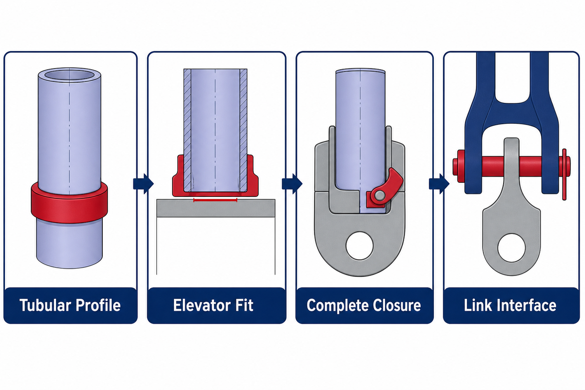
The 4-Interface Fit Framework converts the hypothetical situation of “Will it lift this pipe?” into four verifiable cases. It’s designed as fail-closed. If one interface cannot be verified, stop the selection and obtain the applicable drawing, manual, inspection evidence or manufacturer confirmation before comparing rated capacity.
| Interface | Evidence to collect | Stop condition |
|---|---|---|
| 1. Tubular → support feature | Tubular type, body OD, connection/coupling, shoulder or taper, drawing revision | Profile, dimension or duty is uncertain |
| 2. Support feature → bore/inserts | Exact elevator identity, bore or installed insert, approved compatibility record | Contact, seating, insert identity or clearance is unresolved |
| 3. Body → closure | Hinge, pins, latch/catch, secondary retention, functional confirmation | Incomplete engagement, binding, damage or an ambiguous indication |
| 4. Elevator → links/hoist | Link/bail identity, eye and ear fit, pins/retainers, orientation, system rating basis | Misalignment, mismatched radii, incomplete retention or unclear system rating |
What a useful selection record looks like
A usable record goes beyond “5-inch drill pipe, 150-ton elevator.” It identifies the tubular drawing, body and tool-joint dimensions, support feature, elevator ID, installed bore or inserts, closure, link combination, load basis, and controlled acceptance documents. It names the reviewer and decision date or revision. This lets the next shift confirm whether the configuration changed. When enquiring about steel pipe products from Baling Steel for the tubular supply, request the applicable dimensional drawings and inspection records rather than treating a catalogue description as handling approval.
If one element of the configuration has been changed, the affected interface should be reopened instead of copying the previous approval. A different tool-joint OD can change shoulder seating; an insert swap can change body contact; and a replacement link can change the eye-to-ear fit. A repaired latch can also require verifying the new status. The goal isn’t to create work for its own sake. It’s to avoid a known product name or an impressive capacity value from acting as a substitute for the actual load path.
The “rated capacity isn’t fit” conclusion is a bounded safety inference from these separate interfaces. API’s product taxonomy distinguishes elevators, links, adapters and hooks; the patent example shows body, closure and bail interfaces; and a U.S. offshore safety alert describes how the orientation, alignment and completion of link retention remained important even when high-capacity handling links were being used. None of these sources offer a generic fit formula. Collectively, they show why one capacity mark can’t prove the whole system is suitable.
If you’re comparing a slip-based holding function with an elevator’s hoisting role, the casing slip guide is useful in distinguishing the mechanisms. When all four inputs are complete and a product-level comparison is valid, return to the Welong solution Page as opposed to turning this guide into a duplicate catalog.
| Evidence checkpoint | Value published on the solution Page | Guide-level interpretation |
|---|---|---|
| Portfolio load span | 27 kN–500 T | Confirms mixed duties and units, not one universal rating |
| Portfolio size span | 2-3/8″–36″ | Confirms family breadth, not fit for a specific tubular |
| Drill-pipe example | 2-3/8 in–6-5/8 in; 65 tons / 100 tons / 125 tons / 150 tons / 250 tons / 350 tons / 500 tons | Model, size and support profile still control the valid combination |
| Casing example | 4-1/2 in–10-3/4 in; 100 tons / 150 tons | Coupling or shoulder geometry remains a separate check |
| Tubing example | 1.05 in–5 in; 35 tons / 65 tons / 100 tons / 125 tons / 150 tons | Nominal OD alone does not confirm connection compatibility |
| Drill-collar example | 2-7/8 in–11-1/4 in; 35 tons / 65 tons / 125 tons / 150 tons | Collar support geometry needs its own evidence |
| Side-door example | 2-3/8″–30″; 100–500 T | Closure name does not identify the load-bearing feature |
| Slip-type example | 2-3/8″–30″; 100–350 T | Insert identity and body contact remain decisive |
| Single-joint example | 2-3/8″–36″; 45–60 kN | Single-joint duty is not string-suspension authorization |
Boundary: these are public portfolio examples from the linked solution Page, used here only to show why size and load must be checked together; the current Page, quotation and controlled technical documents remain the commercial and model-level authority
6. Pre-Use Inspection: From Identification Marks to Latch Engagement
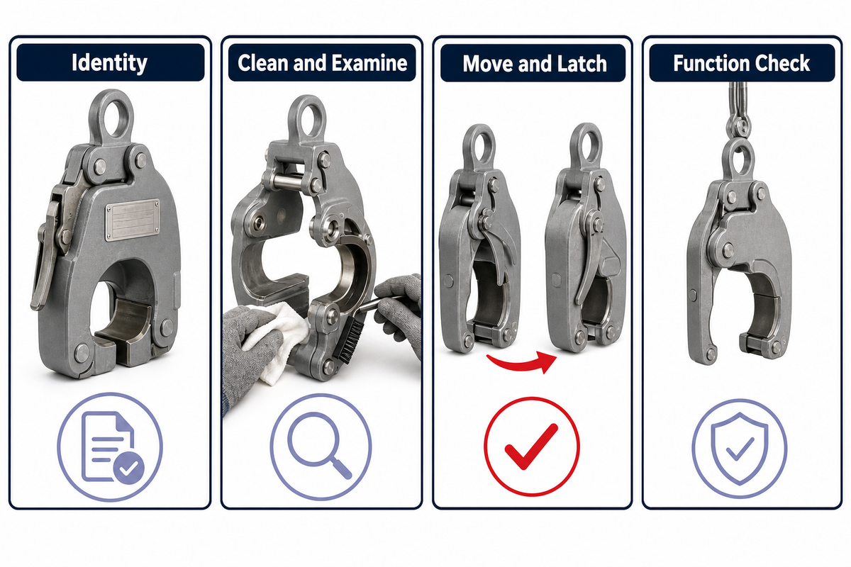
A useful pre-use inspection produces evidence, not a ritual glance. For casing elevators and other tubular-handling elevators, that evidence must match the exact support and closure design. OSHA’s drilling eTool identifies falling tubulars and suspended or moving loads as hazards. It calls for proper use, inspection and maintenance practices and tells workers to stand clear of suspended, hoisted or moving loads. Its “before each tour” suggestions pertain to wire rope, slings, catlines, chains and hooks; they support a high-level work-control principle, not an elevator-specific universal interval.
| Check category | Evidence | Escalate when |
|---|---|---|
| Identity | Manufacturer, model/serial or traceable ID, rated capacity and approved configuration | Marking is missing, altered, illegible or conflicts with records |
| Load surfaces | Bore, shoulder, slips/inserts and contact surfaces checked to the applicable criteria | Wear, deformation, contamination or damage cannot be accepted against controlled limits |
| Body | Condition of body, ears, hinge areas and attachment points | Crack indication, deformation, unauthorized weld/repair or impact evidence appears |
| Moving parts | Free movement, pins, latch, pawl/catch, springs and retention as designed | Binding, excessive play, missing retention or uncertain engagement exists |
| Configuration | Current bore, inserts, accessories and approved configuration match the traceable record | A part is unidentified, substituted or inconsistent with the recorded setup |
| Closure proof | Required latch, lock, indicator and secondary retention reach the approved state | Handle position or appearance is the only evidence of engagement |
| Links and interfaces | Correct link/bail, eye/ear seating, orientation, pins, retainers and connection to hoist | Any interface is mismatched, incompletely retained or not traceable |
| Records and area | Inspection status, open defects, named owner, communication and controlled lifting area | Status is expired/unclear, an open defect exists or area control is not established |
Don’t take examples like “cracks,” “play” or “wear” and convert them into your own rejection criteria. The applicable API RP 8B category, manufacturer criteria, site program and a qualified inspection method determine what’s acceptable. The field check’s job is to detect a mismatch, damage indication or missing record and stop it from becoming an unexamined lift.
7. Rig-Floor Handling Sequence That Keeps the Proof Visible
The Open-Close-Lift Proof is a situational communications framework rather than an all-purpose operational procedure. It shows the crew five actionable decision points that can be aligned with the approved procedures and equipment directions, especially when legacy instructions use phrases such as handle pipe, hold the pipe, lifting or lowering, or safe handling without naming every interface check.
- Brief and control the area. Verify the task, tubulars, tools, exclusion zone, nominated method of communication and the owner of each confirmation. Carry unresolved defects and configuration changes through shift handover.
- Open and present. Use the opening method specified by the manufacturer, align the elevator with the approved load-bearing feature, and maintain clear pinch and suspended-load zones.
- Close and Verify. Confirm full seating, latch/catch engagement and every secondary lock, pin or retainer required by the design. Don’t use the position of the handle as evidence of engagement.
- Restrain the Load. Follow the approved lift sequence. Stop if there are abnormal seated positions, movements, noises, indications, misalignments or a loss of communications. Don’t try to correct anything beneath a suspended load.
- Set Down, Release, Record. Ensure the load is supported before opening, rather than bearing weight through the elevator. Record defects and notable events as well as configuration changes and the next permitted status of the tool.
The U.S. offshore link-installation alert cites an important example of completion evidence. The specific case involved replacing 350-ton elevator links with 750-ton riser-handling links for a 21-inch marine riser; each replacement link was about 15 ft long, weighed roughly 1,200 lb and initially rested at about 45°. In this case, misalignment hindered the latch and pin installation. The alert recommended keeping the hoisting line attached until the retainer was completely installed and loading the links in the correct orientation. The lesson is narrow but important: a sequence should define the exact point at which temporary support can be removed.
For more context on the drilling system around the lift, see the relevant section of Welong’s downhole drilling tools guide. The sequence described here remains subordinate to the rig’s approved lifting plan and current operating procedure.
8. Maintenance Records and Controlled Disposition
“Keep using it” and “scrap it” aren’t the only lifecycle states. A suspect elevator may be removed from active service pending qualified inspection; depending on the applicable requirements and findings, its next state might involve cleaning or lubrication, part replacement, repair, remanufacture, verification, testing, retirement, or documented return to service.
The preview of API RP 8B shows the lifecycle of the equipment in separate sections related to inspection/maintenance, repairs, remanufacture, load tests, and documentation and records. Its contents identify periodic inspection and maintenance categories and frequencies, plus a normative annex addressing wear limits for square-shoulder elevator bores used with non-upset casing and tubing. This is precisely why two opposite shortcuts are unsafe: saying “there are no standardized limits” is wrong, while copying one mechanism-specific limit into every elevator program is also wrong. Review the applicable published version in its entirety, along with the controlled equipment documents.
Field/operator care
- Clean and lubricate only as instructed
- Protect identity and status markings
- Record configuration and observed defects
- Quarantine uncertain equipment
Controlled technical work
- Measurement against applicable wear criteria
- NDE, repair or replacement authorization
- Remanufacture verification and load testing
- Formal return-to-service disposition
A useful equipment file links the tool’s traceable identity to inspections and their evidence, maintenance actions, repairs, the test evidence, configuration changes, defects, and final disposition. It must identify the actual elevator, the applicable criteria, the reviewer, and the rationale for the decision.
9. What Is Changing in Pipe Handling, and What Still Has to Be Verified
The use of mechanized, automated, and robotic systems for tubular handling has been increasing due to an emphasis on safety and efficiency within the oil and gas industry, including work on the oil and gas rig floor. JPT describes safety and efficiency as long-running drivers of this evolution. Also, Drilling Contractor describes robotic drill-floor systems that incorporate a pipe handler, electric roughneck, multi-size elevator, and integrated control systems. These systems can decrease the need for manual handling, relocate tasks, and reduce some worker exposure.
The verification design changes because automation can shift exposure without removing interface risk. A human may no longer pull a handle locally. A sensor, feedback signal, interlock or control-state model may verify part of the sequence. Another thing that remains is the need to establish the identity of the tool, tubular compatibility, insert / bore configuration, full closure, link retention, controlled-area status and response to conflicting indications. Automation won’t make an unknown interface safe, but it can reduce exposure.
The status of the standards changes as well. When checked on September 14, 2026, API’s updates page shows an update of API 8C, 6th edition, for August 2025, older 5th-edition errata and a separate update for the licensing information form for July 2026. These entries must be read carefully. A change of edition, errata, and a licensing statement are separate records and won’t provide a contract basis for every jurisdiction or every project. Confirm the applicable edition, errata, licensing basis and purchaser requirements at the time of use.
Frequently Asked Questions
What are the main types of elevators in drilling?
Drill pipe elevators can be grouped by support mechanism and by closure architecture. Square-shoulder or collar-supported designs bear beneath a compatible enlarged feature; 18° bottleneck designs bear on a matching taper; slip-type designs use inserts to engage the pipe body. Center-latch and side-door describe how the body closes. A second distinction is duty: lifting one joint into position isn’t automatically the same as carrying a string. Record both the support mechanism and the closing architecture, then check the exact tubular profile, fitted bore or inserts, closure and links. A type label alone doesn’t approve the pairing.
How do I select the right elevator size and capacity?
Document the tubular type, body OD, connection or tool-joint geometry, supporting shoulder or taper, and whether the duty involves one joint or a string. Then verify the exact elevator bore or inserts, complete closure, link/bail interface, traceable identity and applicable rating. Compare rated capacity only after those interfaces are accepted. If any profile or configuration is uncertain, stop and obtain controlled technical confirmation.
What is the difference between a square-shoulder and slip-type elevator?
A square-shoulder elevator transfers load beneath a compatible shoulder, coupling or enlarged feature. A slip-type elevator uses fitted slips or inserts to grip the pipe body. The inspection focus therefore differs: shoulder seating and bore condition matter in one mechanism, while insert identity, seating and gripping surfaces are central in the other. Exact acceptance criteria come from the applicable standard and manufacturer documents.
Is API 8C certification enough to approve an elevator for a job?
No. Verify the manufacturing or certification basis, then separately confirm fit, configuration, condition, inspection status, links, retainers, load basis and project requirements.
How often should pipe elevators be inspected?
Use the category and frequency required by the applicable API RP 8B edition, manufacturer instructions, employer inspection program, service conditions and competent-person assessment. The public API preview confirms that periodic inspection/maintenance categories and frequencies exist, but it doesn’t publish the full table. Don’t borrow an interval from another elevator type or use a general web article as the controlling schedule.
Do automated elevators eliminate latch and fit checks?
No. Automation may replace local manual actuation with sensors, feedback, interlocks and coordinated controls, and it can reduce some worker exposure. The system still needs a verified tool identity, tubular match, bore or insert configuration, lock state, link interface and controlled lifting area. Conflicting indications or an unknown configuration require a stop and the approved recovery process.
Ready for a Product-Level Review?
Submit the tubular drawing or connection profile, dimensions of body and tool joint, the operation, the required working load, the preferred mechanism, the link or top-drive interface, inspection and documentation requirements, and the client’s specified standard. Welong can then review the fit of the product, without this guide being considered an engineering approval.
To learn more about Welong’s background and manufacturing capabilities, visit About Welong. You can also review the oilfield and industrial guides for related terminology before preparing a product-level data package.
References & Sources: Source Boundaries
- API Composite List official product-category scope.
- API Monogram and APIQR Latest Updates — edition, errata, and licensing records.
- API RP 8B public preview — scope and contents only, not the full standard.
- OSHA Oil and Gas Well Drilling eTool — high-level hazards and work controls associated with tubular handling.
- U.S. OCS Notice No. 163 — a specific elevator-link installation incident and recommendation.
- Drilling Contractor elevator-strap case — a contractor-published account of one specific operation.
- US20260028886A1 — a patent application used as an illustrative latch-verification design, not a standard.
- JPT: Evolution of Tubular Handling — industry context on the safety and efficiency drivers behind mechanization.
- Drilling Contractor: Mechanization and Automation — examples of integrated robotic drill-floor systems.
- Welong elevator solution page — current portfolio examples; the Page remains the commercial and model-level authority.