Get in touch with Welong Company


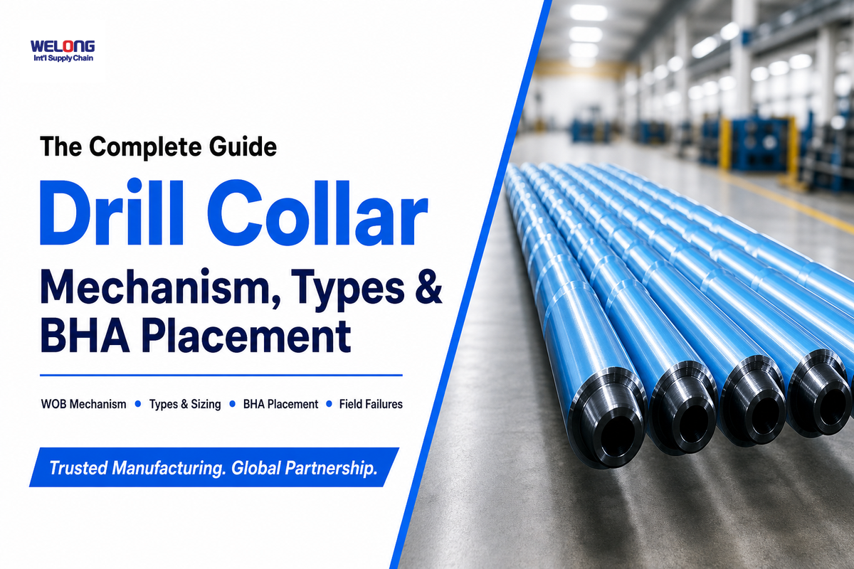
Quick Specs
| Material | AISI 4145H chrome-molybdenum alloy steel, Brinell 285-341 HBW |
| Standard | API Spec 7-1 (2nd Ed., Errata 2 Nov 2025, Addendum 1 Mar 2025) |
| Length | 30-32 ft (regular) or 42-43 ft (long) |
| OD / ID range | 4.75 in – 9.5 in OD / 2.375 in – 3.5 in ID (common sizes) |
| Weight | 22-216 lbs/ft, depending on OD/ID combination |
| Non-magnetic option | Monel/nickel-copper alloy (NMDC), CR1-CR4 corrosion grades |
A drill collar is the thick-walled steel element that transmits weight-on-bit (WOB) by compressing rather than pulling on the bit or stretching the bottom part of the string (drill string). You’ll always end up answering the same three questions: Which kind should we run?
Where do we position it in the string?
How can we tell if we’ve one that’s failing?
This article addresses them by mechanics, not marketing fluff, drawing on the OSHA Oil and Gas Well Drilling and Servicing eTool definition as a starting reference point.
A drill collar is a heavy thick-walled steel pipe positioned just above the bit that uses its weight to deliver downhole compressive force to the bit in the form of weight-on-bit (WOB). They’re most often supplied in two standard length classes – 30-32 ft or 42-43 ft – and machined from API Spec 7-1 compliant 4145H alloy steel. Non-magnetic MWD/LWD (NMDC) collars made of Monel are available for use when steel-induced magnetic interference would affect the survey tools.
Key Takeaways
- drill collars come in two standard length sizes – 30-32 ft and 42-43 ft. They don’t come in one fixed length.
- The familiar 80% of collar weight rule for placing the neutral point in a string is an oversimplified starting point and shouldn’t be relied on to determine actual placement. BHA designers must take into account wellbore geometry, contact conditions and axial forces.
- Of all drill string failures that can be classified as washouts, nearly 95 percent are such. 22% of these washouts can be traced back to a connection with a drill collar.
- In March 2025 API Spec 7-1 was updated with Addendum 1, introducing CR1-CR4 corrosion grades. This was followed by Errata 2 in November.
- Spiral-groove collars weigh approximately 4% less per foot, providing less borehole contact and thus a lower tendency to differentially stick in a borehole, though it’s not a universal replacement.
What Is a Drill Collar? The Weight-on-Bit Mechanism
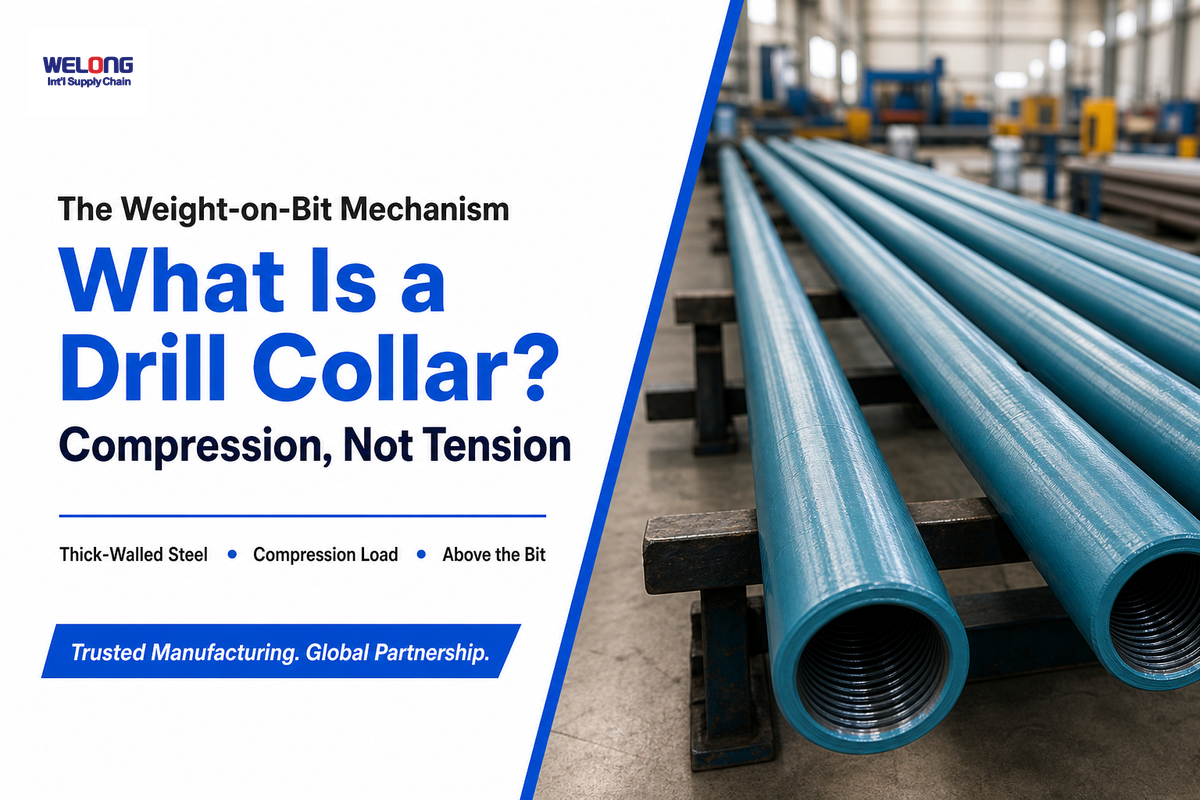
A drill collar is a thick-walled steel pipe section placed directly above the drill bit to transmit weight-on-bit (WOB) — the downward compressive force that lets the bit’s cutting edges bite into rock rather than skid across it. Because the lighter, thin-walled drill pipe above it’s held in tension by its own weight, it can’t supply that compressive force without buckling.
The massive walls (typically 1-2 inches vs. ~1/4-inch for conventional drill pipe, for example) of collars provide the necessary mass and stiffness to remain in compression, resist buckling and transmit the required load without significant deviation from vertical in most holes — the mechanical basis for treating collar length as a primary vibration-control variable, per SPE Journal of Petroleum Technology research on drill collar length. In practice, a crew that run drill pipe too far into the compression zone instead of collars finds out the hard way, because the thin-walled pipe buckles into a corkscrew shape downhole in that application, and the resulting doglegs and casing wear can turn a routine bit trip into a fishing job — precision-machined collar walls exist specifically to prevent that failure mode.
What Are Drill Collars Used For?
Beyond transmitting weight-on-bit, drill collars serve three functions: loading the bit, stiffening the lower drill string to keep a vertical hole straighter, and damping vibration before it reaches the cutting structure — the added rigidity also helps stabilize the drill bit’s path through the formation. Removing any one of these functions shows up on the rig floor as rougher WOB control, harder directional steering, or faster bit wear — which is why designers don’t set collar length by WOB alone.
In practical terms, a driller doesn’t add weight to the bit by pushing harder from surface. Instead, more of the weight of the drill collars is allowed to rest on the bit at the bottom of the hole, and it’s that weight provided by the drill collars — not weight to the drill pipe above — that supplies the downward force at the bottom of the wellbore. The force needed to keep the bit engaged with rock has to be applied to the bit as compression: operators apply weight to the drill string by slacking off hook load until enough weight to the drill bit registers on the indicator, since it’s weight directly from the collars, not tension from surface, that does the cutting work behind successful drilling operations, and running too little of that necessary weight let the bit skate across hard rock instead of biting in.
Drill Collar vs. Drill Pipe vs. Drill Stem: Clearing Up the Terminology
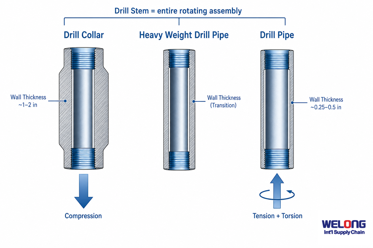
“Drill collar,” “drill pipe,” and “drill stem” are used often enough interchangeably that there’s a non-negligible risk of confusion in a spec conversation, to the point that this is one of the more commonly-searched topics. Per the OSHA oil and gas glossary, “drill stem” is the overall term for the entire rotating assembly, whereas drill pipe and drill collar are two distinct (and mechanically different) internal components.
| Property | Drill Collar | Drill Pipe |
|---|---|---|
| Wall thickness | ~1-2 in (thick-walled) | ~0.25-0.5 in (thin-walled) |
| Primary load | Compression | Tension + torsion |
| Position in string | Bottom, above the bit | Above the collars, to surface |
| Typical length | 30-32 ft / 42-43 ft | ~30-31 ft joints |
A related, heavier-walled product — heavy weight drill pipe — sits between these two components mechanically, and if you’re trying to decide which of the three belongs in a specific BHA position, the HWDP-or-drill-collar selector walks through that decision directly. The entire drill pipe product family and grade list are available on a separate page.
Drill Collar Types: Standard, Spiral, Slick, Square, and Pony Collars
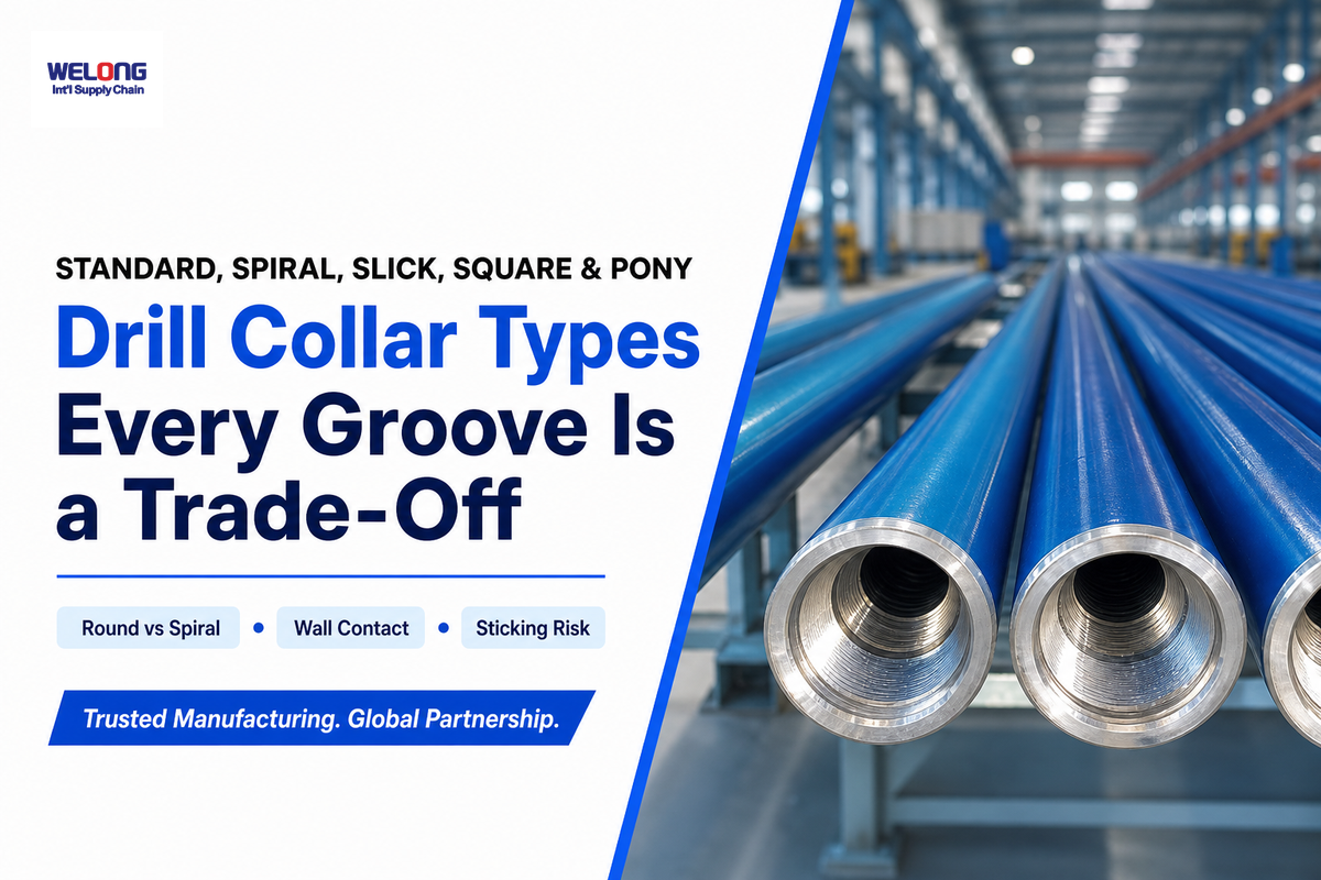
Every drill collar begins as a round thick-walled blank manufactured to API Spec 7-1, and differences are a result of features machined onto the OD, and each alteration is a compromise.
| Type | Cross-Section / Class | Trade-Off / Note |
|---|---|---|
| Standard (round) | Smooth cylinder | Maximum weight per foot; highest wall contact area |
| Spiral (3-groove) | 3 right-hand helical grooves | ~4% less weight/ft; lower differential-sticking risk |
| Spiral (9-groove) | 9 right-hand helical grooves | Lowest wall contact of the spiral family |
| Slick | Smooth, no grooves or flats | Simple to handle; higher wall contact than spiral |
| Square | Flatted sides, diagonal ~1/16 in under bit size | Extra stiffness for straight-hole control |
| Pony (short) | Standard cross-section, 10-20 ft length | Fine-tunes total BHA length/weight |
| Regular length | 30-32 ft | Matches standard rig-floor handling equipment |
| Long length | 42-43 ft | Fewer connections per string; heavier single joint |
| Non-magnetic (NMDC) | Monel/nickel-copper alloy | Protects MWD/LWD survey accuracy near the bit |
| Corrosion grade CR1-CR4 | Non-magnetic stainless alloy classification | CR1 for lower-salinity fluids; CR2-CR4 for harsher/seawater-comparable service |
Note that spiral collars get special consideration here. Although it’s commonly said they reduce weight by about 4% relative to round collar-implying that spiral is just a superior alternative-that’s not the case. In formations where borehole/mud imbalance causes the high risk of sticking (the concern the spiraled groove cutting of wall contact area addresses), it’s an issue; in those with no real sticking concerns, that 4% reduction comes at the expense of no benefit and should be seen as a formation-only choice.
Standard drill collars are available in the round cross-section described above, while spiral drill collars are designed specifically to cut wall-to-borehole contact and reduce the risk of differential sticking in formations prone to it. Choosing the right drill collar is paramount here: a spiral profile isn’t simply an upgrade, it’s a formation-specific trade-off between weight per foot and sticking resistance.
Non-Magnetic (Monel/NMDC) Drill Collars and Directional Surveying
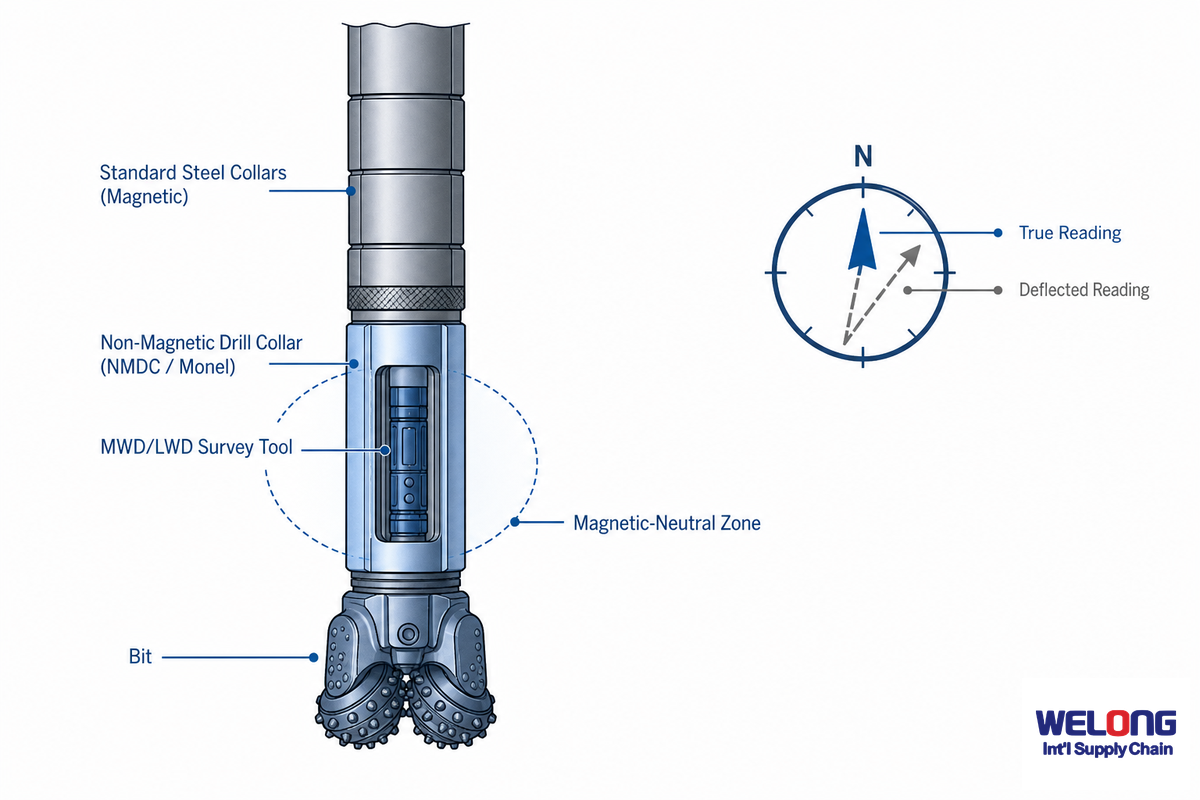
Typical steel in drill collar is sufficiently magnetic to skew MWD and LWD readings-the wellbore’s inclination/azimuth based on the earth’s magnetic field is thereby steered by a local field, creating a skewed position reference for the drillstring and well bore. Non-magnetic drill collar (NMDC), typically made from nickel-copper alloy, is inert in this field and therefore allows the wellbore sensor to be close to it, a mechanism documented in peer-reviewed research on drill string magnetic interference. The risk if this gets overlooked is concrete: a directional driller running an all-steel BHA too close to the survey tool can see azimuth readings drift by several degrees without any alarm, and by the time a gyro survey exposes the error the well may already have missed its target zone — a costly, hard-to-reverse mistake compared to specifying the correct non-magnetic spacing up front. Consider the case of a horizontal well application: even a small, undetected azimuth error compounds over thousands of feet of lateral, so the payoff from getting the non-magnetic spacing right at the planning stage scales with lateral length — the reason NMDC sections are specified around this exact compounding-error problem, not just around the magnetic-neutral-zone concept in isolation.
Industry standard procedure places non-magnetic collar in ten to dozens of feet just above the sensor stack to null the localized field effects — a directional crew running MWD in a lateral well typically specifies that spacing before spud, not after the first bad survey shows up on the rig-floor screen.
The length can be set by BHA designer based on wellbore/MWD/LWD instrument specifics and tolerance of the unit to residual magnetism; API Spec 7-1 2025 Addendum 1 added CR1-CR4 non-magnetic stainless steel corrosion grades based on ASTM G48 Practice A that will work with lower salinity to seawater and above fluid conditions. The selections are based on mud system/wellbore-and covered more in detail for drill collar product lines.
Drill Collar Sizing, Weight, and Length Specifications
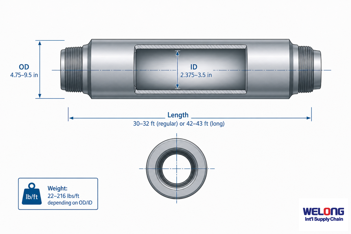
While API Spec 7-1 covers drill collar’s standard dimensions OD, ID, and length, no one is a fixed value but selected from families of standards that can be matched to hole size and BHA design. Buyers researching drill collar sizes and drill collar specifications for a specific rig should treat the ranges below as a starting reference, not a substitute for the mill’s own dimensional report — the reason is that a mismatched OD/ID pairing is a common, avoidable problem when a design is scaled from one rig application to another without re-checking hole size.
How Long Is a Drill Collar?
Most drill collars are run in two standard lengths: 30-32 ft (9.15-9.76 m) regular, matching typical rig-floor handling equipment, or a less common 42-43 ft (12.8-13.27 m) long version. Collar length is one of the first specs a BHA designer confirms.
The longer version reduce the number of connections required for a given collar-string length, minimizing potential leak points and failure sites, at the expense of handling more weight per joint on the rig floor.
Engineering Note
Common OD/ID combinations include 9.5 in/3.5 in, 8 in/3 in, 6 in/2.5 in, and 4.75 in/2.375 in; depending on the OD/ID selected, weights will range from about 22 lbs/ft to more than 216 lbs/ft. A Square Type collar also needs to take account of dimensional constraints on its internal surfaces; in fact, its diagonals (at their furthest extremes, or corner to corner, in other words) are about 1/16 in shorter than the hole diameter to prevent snagging on the bit that just created the space.
Connections, Thread Compound, and Makeup Torque
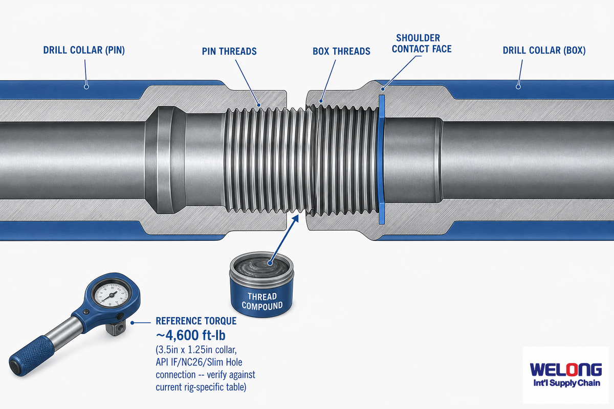
Drill collar threads use the API NC (Numbered Connection) rotary-shouldered profile for drill collar connections, and these threaded connections demand a makeup that’s as critical as the collar’s own dimensions; in fact, many failures traceable to a compound or connection stem not from metallurgic defects, but from incorrect compound use or torquing procedures. Typical reference torques are in the 4,600 ft-lb range for a 3.5 in x 1.25 in drill collar with a 2⅜ in API IF, API NC26 or 2⅞ in Slim Hole connection (though the correct value will be available on a current rig-specific table for the specific compound and connection edition); this range is widely accepted for drill-stem torque tables.
Connection thread compound isn’t optional polish or slick grease. The procedures used to torque drill-stem connections (both oilfield and some manufacturing) are grounded in API RP 5A3, which addresses compound properties for casing, tubing, line pipe, and drill stem products, along with historical oilfield thread formulations, which tend to use finely divided metallic zinc or metallic lead as their base element and keep active sulfur content well under tight limits to prevent galling and corrosion. The compound is smeared on every thread face and shoulder before make-up, allowing the applied torque to do its intended work: generating sufficient shoulder engagement to create a tight seal without the stress/strain that would damage the connection. Note: Some traditional compounds may use a lead base, so users should wear standard PPE when applying and ensure they use a compound approved by their operator rather than just a generic reference, such as the one provided above — the reason this matter in practice is that the wrong compound application is a root cause of premature thread galling on an otherwise sound connection.
Hazards in handling connections are different from those in downholes and in addition to avoiding contact with well fluids, should include the usual precautions against injury when manipulating relatively heavy joints on a rig floor.
OSHA guidelines for oilfield workers point out risks like back injuries, strains, and sprains that come with manually lifting and manipulating collar, as well as struck-by and caught-between risks during hoisting; a rig-floor winch to assist handling, a properly utilized tail rope for guidance and standard good lifting practice can mitigate those hazards.
BHA Placement Mechanics: Neutral Point and Buckling Prevention
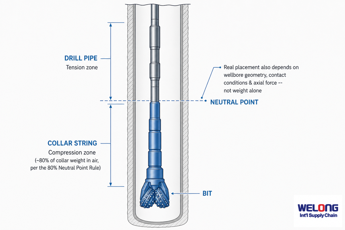
Your deployment of drill collars within the BHA, and their number, is really a compression-handling problem rather than simply weight stacking. Compression is what the drill string are good at, above their neutral point, and tension below; the ideal outcome is to maintain the neutral point within the collar string rather than the drill pipe which isn’t designed for compressive force.
In practice, drill collars are strategically placed directly above the bit and below the drill pipe, forming the heaviest components of the drill string and the load-bearing part of the drill string that keeps the bottom hole assembly (BHA) in compression. As the rotary table (or top drive) turns this steel drill string through varying rock formations, circulated drilling mud carries cuttings up through the annulus while the collars near the bottom of the drill string maintain directional control — the mechanical reason rotary drilling programs treat collar placement as a design variable, not an afterthought.
Applying the 80% Neutral Point Rule
One such common planning rule dictates the length of the collar string so the required WOB isn’t in excess of about 80% of the total air weight of the collar string, allowing approximately 20% above the neutral point for reserve capacity.
| Input | Value |
|---|---|
| Required WOB | 40,000 lb |
| Collar weight in air (6.5 in OD, ~92 lb/ft) | 92 lb/ft |
| Minimum total collar weight needed (WOB / 0.80) | 40,000 / 0.80 = 50,000 lb |
| Minimum collar length | 50,000 / 92 = ~543 ft of collar (rounded up to the next full joint count) |
The result, however, just gives a calculated air weight for the string, real BHA calculations incorporate a buoyancy correction for the fact that the string is hanging in drilling fluid, thereby reducing the weight to what can be thought of as the “real weight,” and also requiring typically a larger amount of collar for that same string length compared to air-weight calculations alone. However, even after making this adjustment, the result is still simply a planning tool rather than a reliable buckling prediction tool. Modern drilling calculations, per published buckling-behavior research, have moved on from using the neutral point as the only critical threshold and understand that real buckling is a complex interaction of the wellbore geometry, how it contacts the borehole wall, its axial force and its bending stiffness rather than solely where the weight is located. While the 80% rule may give you a reasonable starting number for your collar run, you need a real time weight-indicator and torque-and-drag analysis to know that the calculated neutral point is actually staying where it’s assumed to be, as real-world conditions in a directional well commonly reveal the neutral point shifting considerably from where it was initially calculated as hole angle, mud density and frictional conditions change during the run.
“Treating the neutral point as a fixed 80%-of-weight threshold works as a planning starting point, but field practice increasingly accounts for wellbore geometry, contact conditions, and dynamic torque and drag when finalizing BHA collar length in directional wells.”
Manufacturing, Alloy Steel, and Inspection Standards
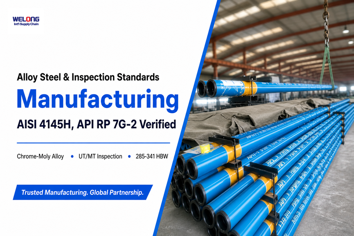
The drill collars are machined from solid AISI 4145H chrome-molybdenum alloy steel bar, heat-treated to a Brinell hardness of 285-341 HBW per API Spec 7-1’s material spec (a somewhat broader 255-341 HBW band is cited by a couple of other industry references, but the single-specification, 285-341 is the one referred to here), with a Charpy V notch impact toughness of at least 40 ft-lb (54.2 J) at 20°C to withstand brittle fracture when used in cold environments.
In this context, collars are manufactured this way rather than from plain carbon steel because the chromium and molybdenum in the alloy raise hardenability and toughness at the wall thicknesses involved; the 4145H specified by API is itself a higher-carbon variant of the more familiar 4140 alloy family used elsewhere in oil and gas drilling tubulars. Every collar begins life as one of these solid bars of steel drill stock, bored and turned to the dimensions covered above as part of the standard drilling process, and an alloy drill collar machined this way is designed to withstand the compressive, torsional, and vibrational loads of the BHA over years of repeated trips.
The fitness of used API RP 7G-2 will involve ultrasonic (UT) and magnetic particle inspection (MT) of the used drill stem elements, which also include the drill collars. Which inspection methods will be chosen will depend on wall thickness (per summary reports for this inspection standard). Thinner walls may require the faster method of electromagnetic inspection, while those with thicker walls will require a full length ultrasonic inspection to accurately test for flaws inside. Skipping that step is exactly how a collar with a fatigue crack too small to see with the naked eye get sent back downhole, where it can propagate into a washout or twist-off on a later run — the inspection cost is trivial next to a stuck-pipe fishing job in a real field application, because a skipped or rushed inspection cycle is a well-documented root cause of preventable in-service failures.
Field Failure Modes: Washout, Twist-Off, and Thread Galling
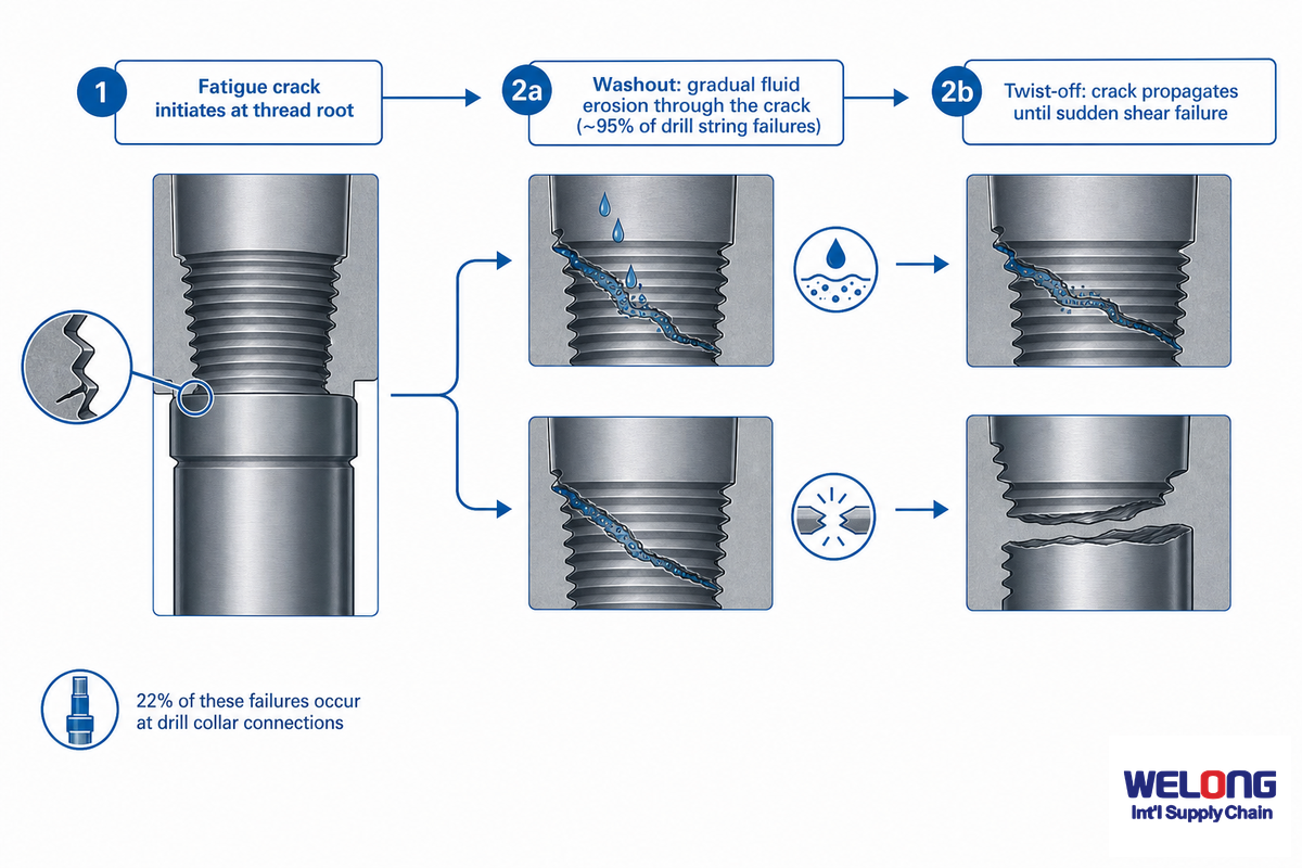
As the common citation in compilations of secondary oilfield failure data has it, one aggregated field study of the recorded instances that it reviewed placed washout at about 95% of drill string failures, with the rest coming in as twist-offs–and within that cohort, 22% came at drill collars in that particular data set vs. 65% in the slips area. (View those figures as illustrative of a widely reported pattern based on one specific dataset, not as an industry-wide contemporary rate confirmed across all field environments and equipment.) At bottom, the driver for either mode is similar: a fatigue crack, which leads to gradual drilling fluid wall erosion washout, versus an unchecked crack-or undetected stress riser-propagation which suddenly shears as a twist-off. At the deeper level: downhole vibration-and particularly high-frequency torsional oscillation (HFTO)-builds-and then focuses on the thread roots, generating bending stress. The risk of HFTO, per IADC Drilling Contractor reporting, is especially heightened for the rotary steerable system (RSS) BHA.
Tracing the Washout-to-Twist-Off Failure Sequence
Washout that, unrecognized, begins at a fatigue crack that progresses until the connection can no longer withstand the stress and it snaps off as a twist-off: One sequence, not two separate events.
⚠ Common Mistakes
- Overly rough handling and tong-die scarring, creating a stress riser even before the string is put in downhole.
- Over- or under-making up the connection; either extremes can be detrimental to thread root integrity over time.
- Failing to recognize the typical lead time of a few days for such washout signals-changes in standpipe pressure and torque trends that usually precede a failure, not hours.
✔ Early Warning Signs
- A steady decline in pump pressure without an equivalent change in flow rate, indicative of a leak from a developing washout.
- Variable or drifting torque values that don’t align with formation variations or changes in hydraulic behavior.
- The presence of galling or visible crack indications on the thread upon connection breakout inspection.
Industry Outlook: Directional Drilling Growth and API 7-1 Evolution
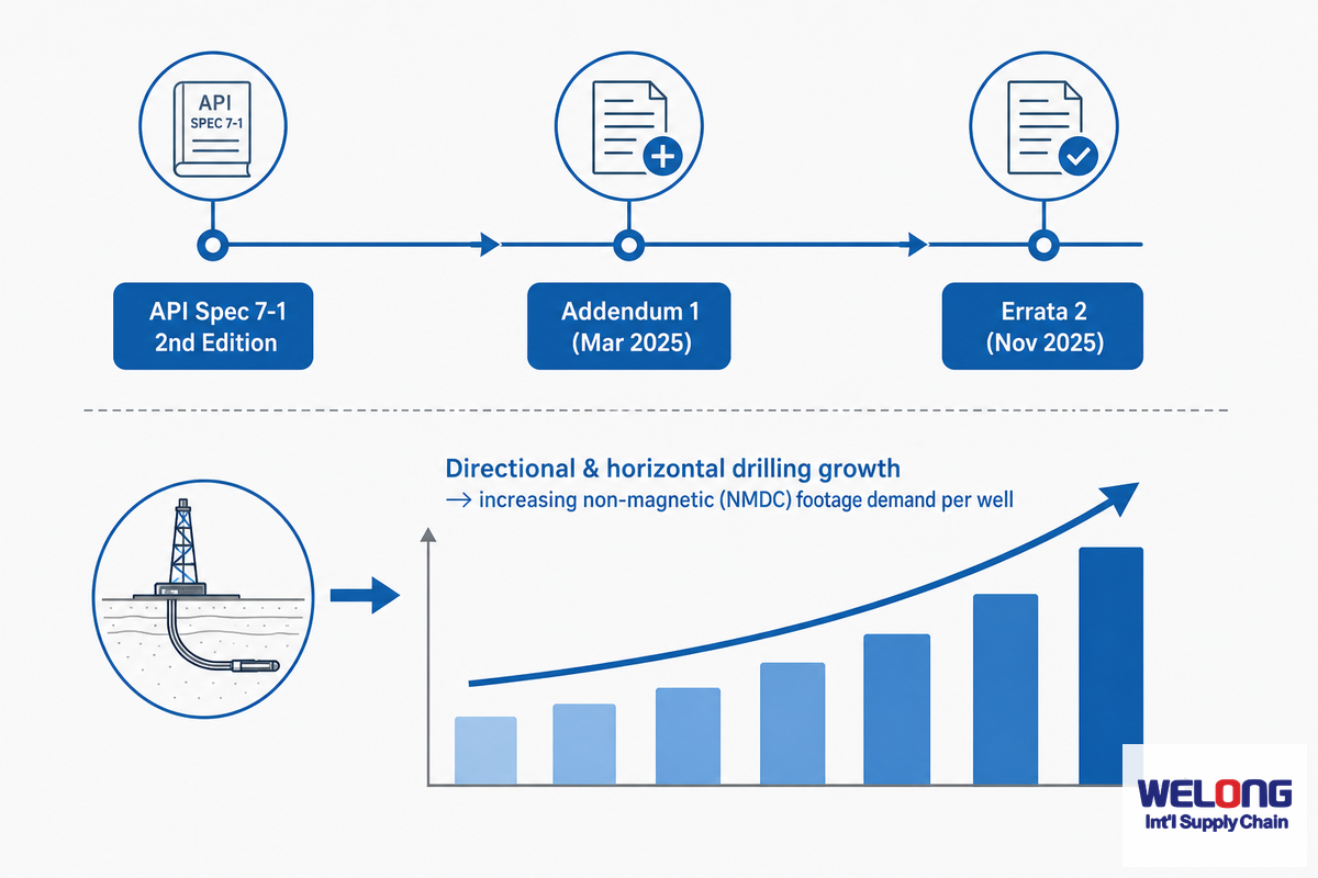
API Spec 7-1’s second edition-introduced in March 2025 with Addendum 1, which established a CR1-CR4 classification for corrosion resistance of nonmagnetic stainless steel alloys, followed by Errata 2 in November 2025-brought significant changes to specifications governing nonmagnetic drill collars. (An “Addendum 1 only” specification buyer would be behind by one version of the package.)
A surge in demand for nonmagnetic collars is attributable to a continuous transition towards directional and horizontal drilling, which necessitates the precision provided by a nonmagnetic BHA section to ensure accuracy for MWD/LWD surveys. Longer lateral wellbores have a direct impact on the requirement for increased nonmagnetic footage per well. Although one widely cited market-research estimate puts the broad drill collar market at billions of dollars in sales with a reported mid-single-digit compound annual growth rate (CAGR) through the early 2030s, that figure reflects the broader industry and isn’t a precise demand forecast for collars specifically. The impact of new standards on procurement, however, is a much more actionable metric.
Frequently Asked Questions
Q: What does “collar” mean in drilling?
View Answer
In the context of drilling, collar is a thick-walled tubular of the drill string, not to be confused with a common mechanical shaft collar or a clamp. The mass and rigidity for a drill collar to endure compression at the bit and resist buckling for the duration of a run depend on its wall thickness rather than a fitted ring or shoulder.
Q: What is the difference between a drill collar and a drill pipe?
View Answer
A drill collar has thick walls designed to carry compressive loads next to the bit, while drill pipe is thin-walled and designed to transmit tension and torque from the bit up to the rig floor. Each component is built for a different load case.
Using these two roles within a single component would create either a weight penalty for an over-designed pipe segment or a buckling risk in an under-designed collar segment, which is why the drill string keeps these functions and dimensions separated throughout the entire BHA design.
Q: How heavy are drill collars?
View Answer
Weight per foot ranges from approximately 22-216 lbs/ft across typical OD/ID size ranges, with a standard mid-size collar (e.g., approximately 6.5 inches OD) falling at about 90 lbs/ft. Total weight of a full collar string is derived by multiplying the per-foot weight by the collar length, chosen to ensure adequate weight-on-bit at the selected neutral point margin.
Q: What is an NMDC in drilling?
View Answer
NMDC refers to non-magnetic drill collar, typically made of a Monel or equivalent nickel-copper alloy collar placed near MWD/LWD tools to avoid the impact of steel on magnetic field measurements. The CR1-CR4 designations relate to its corrosion resistance for the specific mud system being used.
Q: How often should drill collars be inspected?
View Answer
There’s no fixed calendar inspection interval for drill collars; the industry standard API RP 7G-2 sets inspection frequency based on operating conditions and operator risk tolerance rather than the calendar date. Full UT/MT inspections are typically performed between wells or at rotating-hour intervals agreed with the operator before the program start.
Highly-stressed, corrosive, or high-frequency downhole oscillations (HFTO) associated with steering tools like the rotary usually demand much shorter inspection intervals compared to less demanding, lower-vibration vertical drilling programs such as those using a drilling assembly at moderate parameters.
Q: Can a drill collar be repaired after a washout or crack?
View Answer
If there is sufficient wall thickness remaining, a washout in the connection area may sometimes be re-cut to accommodate a smaller connection size. However, body cracks or extensive galling on a joint generally cause it to fail the criteria under the RP 7G-2 grading system.
Why We Write This
Since 2001, China Welong has been a leading manufacturer of downhole drilling tools, including drill collars. This guide covers the mechanical principles that guide the selection of drill collar, placement within a BHA, and diagnosis of common failures – the primary engineering questions asked by drillstring designers and procurement professionals considering suppliers. Please refer to our full line of drill collar products for specific models, corrosion-grade options, and ordering. Reviewed by the China Welong technical team.
References & Sources
- Oil and Gas Well Drilling and Servicing eToolOccupational Safety and Health Administration (OSHA)
- API Spec 7-1: Specification for Rotary Drill Stem ElementsAmerican Petroleum Institute
- Drill Collar Length is a Major Factor in Vibration ControlSociety of Petroleum Engineers, Journal of Petroleum Technology
- Buckling behavior researchPetroleum Science, Springer
- Demagnetizing the drill string: magnetic interference in the Far North and in PakistanJournal of Petroleum Exploration and Production Technology, Springer
- Drill string failure analysis researchScienceDirect (open access)
- US7845429B2, Determining drillstring neutral point based on hydraulic factorUSPTO / Google Patents
- Mitigation strategies advance as industry digs deeper into HFTO originsDrilling Contractor, International Association of Drilling Contractors (IADC)
Related Articles
- Drill Collar Product Line & Selection Frameworkfull spec sheets, type-by-condition selection, and RFQ
- Heavy Weight Drill Pipethe transition-zone component between drill pipe and drill collars
- HWDP or Drill Collar? A 3-Question Selectordecide which component belongs in your BHA
- Drill Pipe Grades & Connectionsfull product line and grade-to-connection selection chart
- Drilling Jarsthe fishing-and-release BHA component adjacent to drill collars
- About China Welong20+ years manufacturing downhole drilling tools
![Casing, Tubing & Drill Pipe Elevators [Field Guide]](https://welongoiltools.com/wp-content/uploads/2026/09/casing-tubing-drill-pipe-elevators-guide-featured-768x512.png)
![Choke & Kill Hose: [Field Guide]](https://welongoiltools.com/wp-content/uploads/2026/07/choke-kill-hose-guide-featured-1-150x150.png)