Get in touch with Welong Company

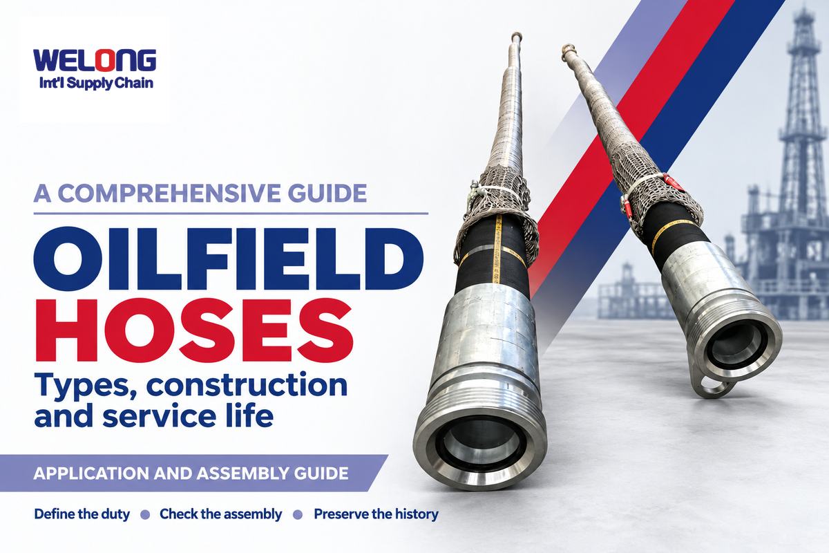
Oilfield Hoses transport drilling fluid, transfer water and petroleum, deliver hydraulic power, and perform special well-control duties. The oil and gas industry uses several different assemblies under that name. A hose that supplies water to a frac site performs a different job from a high-pressure pumping line, even when both appear in the same equipment catalogue.
This publication identifies families, layers beneath the cover and the conditions that govern the service life. An oil and gas hose needs a defined job first; then examine the entire assembly, including its end connections.
Updated October 2026
Quick orientation
Oilfield hoses are flexible assemblies for distinct oil and gas duties. Working limits belong to the specified hose, fittings and service conditions together. Transfer, drilling and well-control lines require different construction and qualification.
Key points
- An oil-resistant tube can still be unsuitable for gasoline.
- The reinforcement carries pressure; the outer cover protects it from exposure and wear.
- Operating pressure, temperature, fluid and movement must be evaluated together.
- Inspection history helps plan maintenance and downtime; replacement timing follows the actual assembly and duty.
Oilfield Hose Types and the Jobs They Do
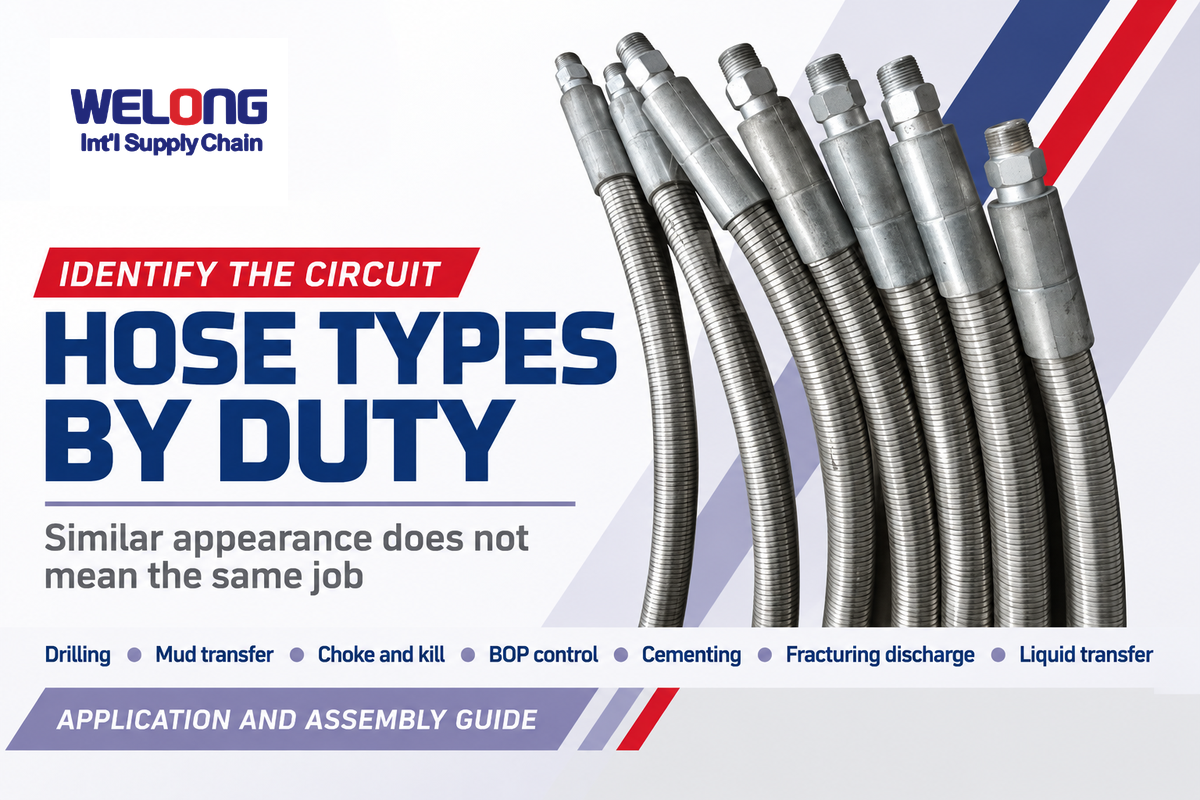
Oilfield hose types vary according to the fluid, pressure function and movement they serve. Rotary drilling, mud transfer, well control and hydraulic power place different demands on a line. Grouping hoses by job makes the distinction clearer than sorting them by diameter, cover appearance or the largest pressure number in a catalogue.
What are the different types of oilfield hoses?
Seven useful duty groups are rotary/vibrator drilling, mud suction and transfer, choke and kill, BOP control, cementing, fracturing discharge, and petroleum or water transfer. These job groups are descriptive, and some manufacturers subdivide their product ranges differently. A complete assembly must be suitable for the equipment and operating conditions.
| Duty group | What the line does | Distinction that matters |
|---|---|---|
| Rotary / vibrator drilling | Conveys drilling mud through flexible parts of the circulation system. | Movement and pressure pulsation are part of the drilling duty. |
| Mud suction / transfer | Moves drilling fluid between tanks, pumps and supporting equipment. | Suction resistance and transfer pressure require their own limits. |
| Choke and kill | Serves specified well-control flow paths. | Well-control service adds qualification requirements beyond bore and pressure. |
| BOP control | Carries control fluid to blowout-preventer equipment. | Hydraulic control service differs from conveying well fluids. |
| Cementing | Conveys cement slurry in the specified pumping circuit. | Slurry and pumping conditions shape the required assembly. |
| Fracturing discharge | Carries fluid on the high-pressure discharge side of treatment pumping. | Supply water to a frac site belongs to a different pressure circuit. |
| Petroleum transfer / water transfer | Moves the specified liquid between storage and process equipment. | Crude, refined fuels, produced water and clean water are different media. |
Continental’s description of drilling hoses distinguishes flexible connections to the top drive and between the mud pump and standpipe. Transfer hoses elsewhere on the rig don’t acquire drilling duty merely for having similar fluids.
During hydraulic fracturing, supply lines may move larger volumes of water to storage or blending equipment. Fracking discharge then routes treatment fluid to the wellhead under a different operating envelope. Keep the two circuits separate when looking at a drawing or discussing hoses for oil and gas operations.
Hose Construction: Tube, Reinforcement and Fittings
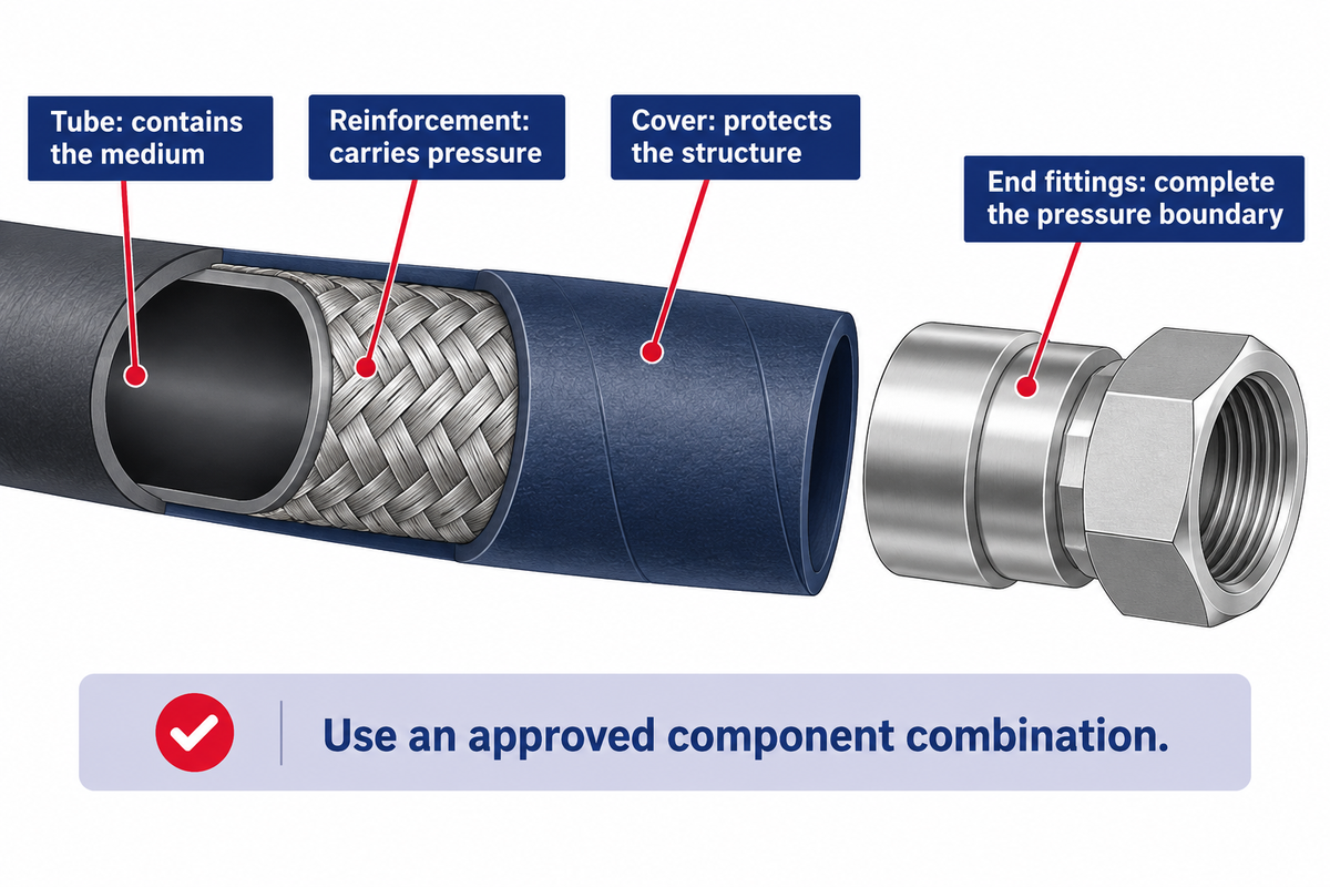
A reinforced hose functions similarly to a flexible composite. The inner tube contains the medium, the reinforcement carries the pressure, and the cover protects the structure. End fittings complete the pressure boundary. Because each component has a distinct function, a tougher looking cover won’t create a higher pressure rating or compatible connections.
In bonded hose construction for oil drilling, Continental cites a polymer lining with a steel cable reinforcement. Other industrial hoses have different reinforcement arrangements. Braided wire, spiral wire, textile and supporting helices are design choices for particular duties, rather than interchangeable versions of the same assembly.
Connections require the same analysis as the hose body. A coupling, ferrule, along with the hose, must be from an approved combination, regardless of the type of attachment (crimp, swage, or another manufacturer-defined attachment). The HSE hydraulic-injection bulletin states fittings should be matched to the original equipment manufacturer’s specifications, along with the hose, during maintenance or replacement.
“The hose assembly maximum working pressure is governed by the lowest maximum working pressure of the components.”
The hose specification and end-connections requirements should both be evaluated during a replacement assessment. For gas applications, the public scope of BS EN ISO 4080:2024 also distinguishes permeability through the hose wall, at the hose/fitting interface, and through the complete assembly. A wall-material result addresses only one of those objects.
Working Pressure, Temperature and Fluid Compatibility
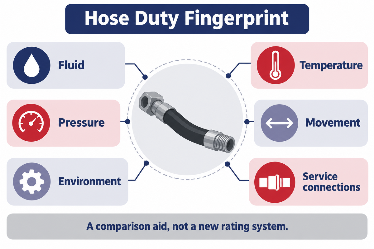
Working pressure is a service limit defined by a set of conditions, not a permission to use a hose with any service fluid. Temperature and chemistry of the service fluid can change the nature of the acceptable service. The complete assembly includes fittings and other pressure-containing components, and a hose body with a larger number can’t resolve all limiting conditions.
Hose Duty Fingerprint
Hose Duty Fingerprint brings together fluid, temperature, pressure, movement, environment and service connections to explain the actual service of the assembly.
For the fingerprint of fluids, use the identity and composition of the fluid, including solids or additives, instead of just “oil.” Record working and transient pressures separately from proof-test or burst values. Include movement path, exposure and connections. Fingerprint is an aid for comparison of service conditions, not a new rating system.
A concrete example comes from Gates product 46890003, 80BG1603: its page lists a 5-inch inside diameter, 300 psi working pressure and a 51-inch minimum bend radius for drilling-fluid transfer. The nitrile tube might suggest broad petroleum compatibility, yet Gates specifically excludes refined petroleum products such as gasoline. The liquid name matters even before pressure enters the discussion.
What is the strongest hydraulic hose?
There’s no universal best hydraulic hose; choose an assembly qualified for the right pressure, fluid, temperature and movement all together. Reinforcement construction and published pressure ratings assist in comparing candidates, but neither creates a universal winner. Higher pressures can require a different design, while a lower-rated component or an incompatible medium can still limit the complete assembly.
Consider a hypothetical maintenance substitution involving 80°C water. ISO 18752:2025’s public abstract lists water only up to 70°C within its scope, even though specified oil-based fluids in CS, CC and DC types extend to 120°C. Comparing 80°C with the water limit gives a clear mismatch. Borrowing the oil limit would conceal it. This example concerns that hydraulic standard, not every oilfield hose.
For flammable-liquid transfer, electrical continuity needs attention alongside mechanical integrity. HSE’s earthing guidance relates to conductive hose construction and contact between metal ends. Steel reinforcement used to carry pressure should not simply be assumed to provide the required static-dissipation arrangement.
Drilling Hoses, Choke and Kill, and BOP Control
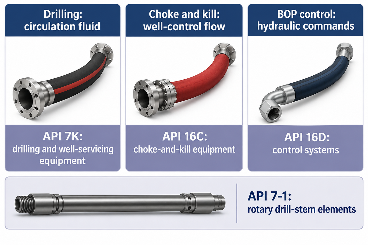
Drilling, choke-and-kill and BOP control hoses belong to different circuits. During drilling operations, drilling lines convey circulation fluid, choke-and-kill lines help control well pressure through specified well-control paths, and control hoses transmit hydraulic commands. Similar bore sizes or pressure markings can conceal significant differences in the properties of the media, motion and temperature exposure as well as qualifications, especially where the line influences well-control functions.
The American Petroleum Institute’s program documents list API 7K for drilling and well-servicing equipment, API 16C for choke-and-kill equipment, and API 16D for control systems for drilling well-control equipment. API 7-1 concerns rotary drill-stem elements. A company’s API 7-1 statement therefore addresses a different product scope from a hose qualification.
For mud pump and drill hoses, determine the line’s location in the circulation system. Whether the equipment supports vertical or horizontal drilling, identify its actual circuit. For pressure control, begin with system requirements. A high-pressure drilling requirement is more specific than pressure alone. A general hydraulic line chosen solely by pressure can omit the specified connection, movement or fire-performance requirement. The responsible systems designer must resolve any proposed substitution against the actual assembly specification.
Current document references matter too. Use API and ISO references for the product scope each document describes. API’s published update list includes API 16C third edition, Errata 3, dated December 2025. Edition and amendment details belong with the applicable assembly requirement; a planned future revision date is different from a published document.
For the corresponding product families, see drilling hose assemblies, the choke and kill hose family, and BOP control hose.
Hose Routing: Movement, Bending and Abrasion
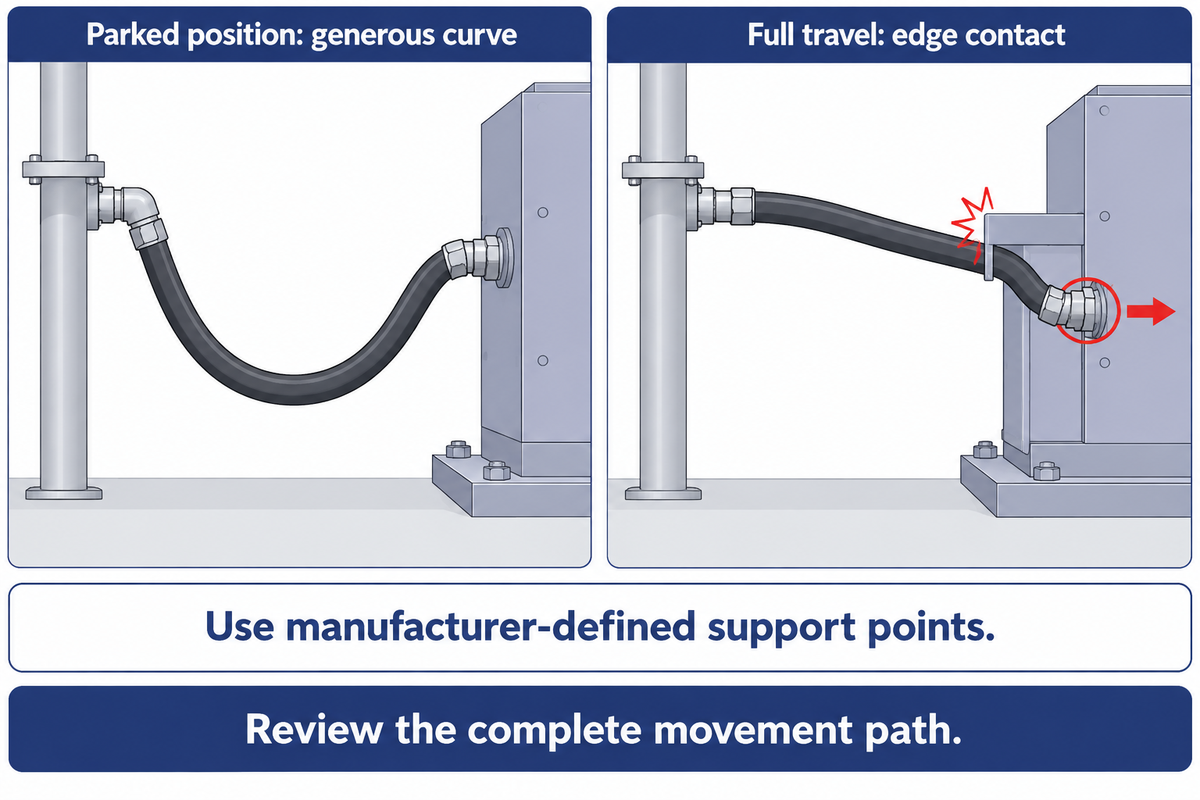
Hose routing must ensure full movement of the assembly while limiting bend, twist, contact and external loads. A line that rests smoothly may become taut or rub against equipment while moving. The exact assembly’s installation instructions determine its bend radius, support arrangement and handling requirements; appearance at one position is an incomplete check. A check of a line’s parked position is an incomplete check.
The Continental high-pressure flexible-line user guide covers various aspects of line design, including installation and operating conditions. In harsh conditions, minimum bend radius still describes an allowed curve for a specified product; it is not a universal multiple of diameter. Bending close to an end connection, twisting the line or pulling on a coupling changes how loads enter the assembly.
Picture a rig with moving equipment that’s connected to fixed pipework by a replacement line. At the parked position, the spare line makes a generous curve. At full travel, the curve shifts against a steel edge and the end connection carries a pull. Scuffing or wearing at the edge is a routing concern. Choosing by end-to-end length doesn’t address either problem. Reviewing the installation requires the movement path, nearby obstructions and manufacturer-defined support points, not a single picture of the equipment at the parked position.
Outer protection and routing address different causes of damage. For example, an abrasion-resistant cover may withstand contact better, but repeated contact should still be addressed. Extreme temperatures, chemical splash and weather exposure add on to the concerns. Corrosion resistance of an exposed coupling and fluid compatibility of the tube concern different parts of the assembly. A protective sleeve must itself suit the assembly and surroundings; it does not change the pressure rating underneath.
Hose Failure: Recognizing Damage and Test Limits
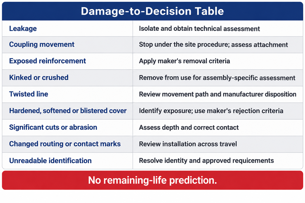
Hose failure may involve the tube, reinforcement, cover or end connection, with different visible clues and different hidden damage. Leakage, exposed reinforcement, deformation and coupling movement require the application of the site’s isolation and assessment procedure. A pressure test is performed to record the component performance under test conditions. Maintenance must also take into account the assembly’s subsequent exposure and condition post test.
Damage-to-Decision Table
Damage-to-Decision Table relates what’s observed to possible failure mechanisms and to the next bounded maintenance decision.
| Observed damage category | Possible issue | Maintenance response |
|---|---|---|
| Leakage | A pressure-boundary or connection fault. | Remove from operation through the site isolation procedure and obtain technical assessment. |
| Coupling movement | The attachment or applied load may have changed. | Stop operation under the site procedure; have the complete attachment assessed. |
| Exposed reinforcement | The pressure-carrying structure is exposed to damage. | Apply the maker’s removal criteria; replacing a cover does not restore reinforcement. |
| Kinked or crushed section | The hose geometry and internal structure may be damaged. | Remove from use for assembly-specific assessment, including the routing cause. |
| Twisted line | Installation or movement is imposing torsion. | Review the complete movement path and manufacturer disposition. |
| Hardened, softened or blistered cover | Temperature, fluid exposure or deterioration may be involved. | Identify the exposure and affected layers; use the maker’s rejection criteria. |
| Significant cuts or abrasion | Outer protection and possibly reinforcement have been damaged. | Have the depth and permitted disposition assessed; correct the contact point. |
| Changed routing or contact marks | Support, motion or clearance may have changed. | Review the installation across its travel with the responsible technical owner. |
| Unreadable identification | The assembly and its service limits cannot be reliably matched. | Resolve identity and approved requirements before accepting it as a replacement. |
Jason Hose Solutions’ replacement guidance lists cover damage, leakage, exposed reinforcement, and deformed areas as defects found in hydraulic service. The manufacturer’s own criteria are critical for assessment of these oil and gas applications. For example, Continental grants qualified repair services for some covers, armor and couplings; that’s a controlled manufacturer service, not an approval for unauthorized field repair.
Testing creates hazards. In a March 2014 WorkSafeBC investigation, rapid pressurization using high-pressure air caused an LNG decanting equipment test to result in an explosion and a hose whip which seriously injured a nearby worker. This was a historical non-drilling incident. It illustrates why test-medium selection, isolation, personnel separation and an engineered procedure belong with competent testing personnel; adding restraints alone had not controlled that event.
Do
- Follow the site’s isolation and assessment procedure.
- Keep the assembly identification with its findings.
- Use the manufacturer’s permitted disposition.
Don’t
- Search for a pressurized leak with a hand.
- Tighten a suspect connection under pressure.
- Treat a past test as a replacement for current inspection.
Service Life: Inspection, Storage and Replacement
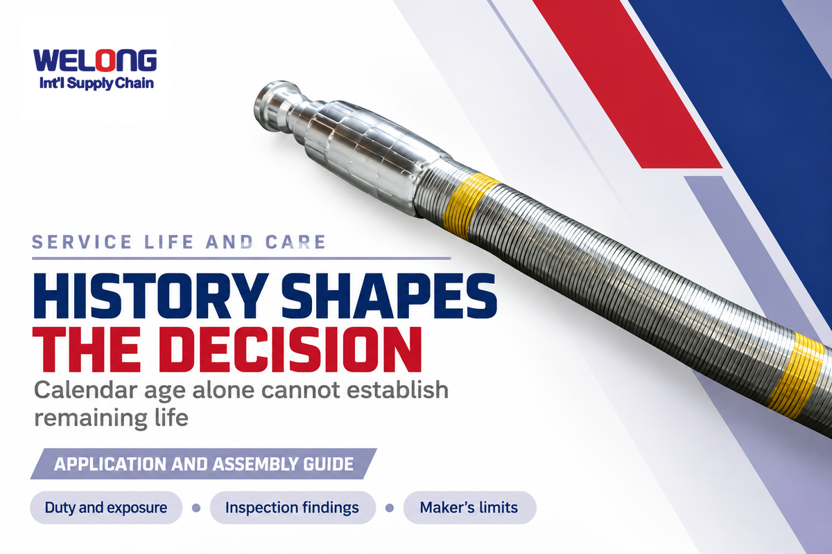
Oilfield hose service life is based on the actual assembly, operating and maintenance history. External damage and fatigue can shorten service life before the calendar limit is reached. Inspection intervals, retirement criteria, and storage requirements are mainly determined by the manufacturer and operator’s maintenance program and changed conditions rather than a specific number of years.
Which hoses last the longest?
For long service life in a particular job, select a hose with materials and reinforcement and installation suited for the job, and keep its condition within the maker’s limits. Thicker cover and more reinforcement don’t guarantee longer service life. Cycling, exposure to temperature and fluids, and abrasion must be considered in addition to the actual product and service history.
Continental’s user guide emphasizes external damage and reinforcement fatigue and links inspection to service history, severity and criticality. Shifting a calendar limit to a different family of hose would change the assumptions behind the operating limits.
As an illustrative example, consider two assemblies of the same age. One has stayed in controlled storage; the other has cycled on moving equipment near an abrasive contact point. Even though they may have the same date, exposure may differ significantly. The maintenance owner must understand the identification, duty, installation changes, inspection findings, and manufacturer limits and assumptions for each case. No remaining-life figure can be determined by the hose dates alone, and the stored spare also must have the maker’s storage and pre-installation checks.
Record changes in fluid or temperature when a system is changed. Don’t modify a line that previously carried one fluid and use it as a spare for another fluid without confirming compatibility. Store assemblies according to the manufacturer’s instructions. Their end fittings should be protected and their identification should be legible. They should be protected for later inspection.
Replacement Planning: Bulk Hose versus a Complete Assembly
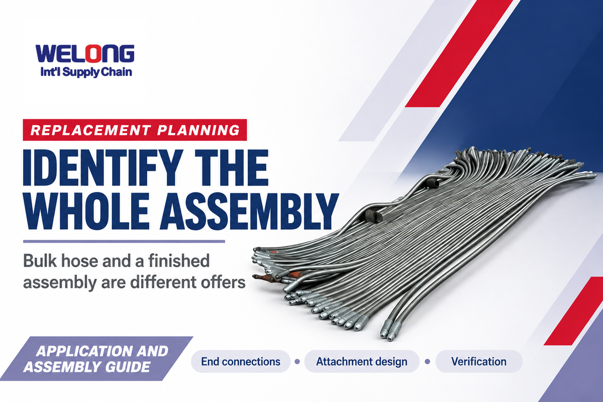
Replacement planning starts with the complete assembly rather than the price per length of hose. End connections, attachment design, and verification are part of replacement. Separating the body of hose from the completed assembly helps explain why two similar offers can represent different items, even before installation or freight comes into play when comparing offers.
Industrial hose manufacturers define hose designs; assembly fabricators complete the specified end connections. Supply-chain integrators coordinate the supply of the required products and services. The industrial hose market includes both bulk hose and finished assemblies. One entity can perform several functions. A workover replacement raises the same identification question. Identify the actual manufacturer and assembly requirements rather than assuming a supplier’s general quality certificate covers every finished line.
China Welong’s company background describes an integrated supply-chain service provider founded in 2001. For product options and a defined supply scope, use the oilfield hose solutions page. Compare replacements against the approved assembly identification before considering availability or timing of order.
Digital Hose Management: What the Records Can Prove
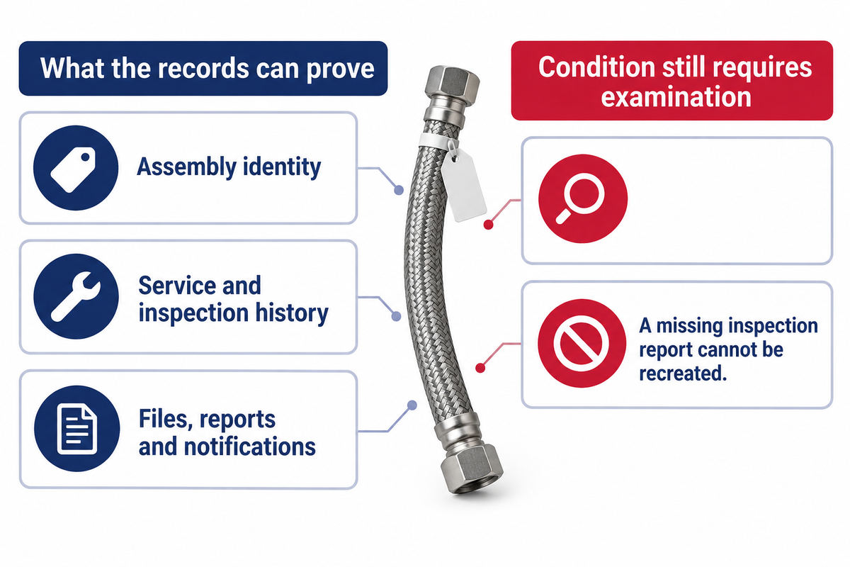
Digital hose management connects an identified assembly with its service records, inspection findings and planned actions. The main advantage is continuity. The practical benefit is continuity: The next maintenance team is able to retrieve the correct service history. In the interim a tag or entry in a database is a surrogate identifier. Assessing the condition of an assembly still requires examination against criteria provided by the manufacturer.
Continental’s C-IQ service description gives a current example: an electronic hose register with asset overviews, file management, reports and notifications. Those provide record management.
Imagine a removed line of equipment with a tag, but no inspection report. The electronic register is able to identify the assembly, but is unable to recreate a missing inspection report. Attach the replacement identity, service change and completed disposition to the record so that the next shutdown starts with the actual history. That way, the next shutdown is able to start with the correct equipment history.
Key takeaway
Match an oilfield hose assembly to its complete duty, then preserve the identification and condition history needed to maintain that match.
Frequently Asked Questions
What kind of hose is used for oil?
Use a hose approved for the specific oil service.
Oil service requires a hose whose tube and complete assembly are approved for the actual fluid and conditions. Crude oil, diesel, hydraulic oil and oil-based drilling fluid do not represent one identical duty. Temperature, composition, suction or pressure service, end connections and movement must be checked against the specific manufacturer’s published limits.
Are oilfield hoses recyclable?
Ask a specialist processor about the actual assembly and residues.
Recycling options vary with the hose materials and residual contamination. An assembly may combine elastomer, reinforcement wire and metal couplings that need separate processing. Ask a specialist waste or recycling contractor about the actual item and its service history. A hose that carried hydrocarbons needs that assessment before entering a proposed recycling stream.
What certifications should you look for in oilfield hoses?
Match the documented product scope to the required service.
For certified hoses, look for evidence that matches the particular hose assembly and its intended service, rather than a company logo or a general certificate. Relevant documentation may identify the manufacturer, applicable specification, product scope, assembly identification and required tests. An organization-level quality-system certificate does not by itself establish that every hose meets a drilling or well-control specification.
Can damaged hose fittings simply be tightened?
Isolate and assess the suspected fault first.
A suspected leak or moving coupling requires the responsible crew to follow the site isolation and assessment procedure. Tightening a connection under pressure can expose personnel to stored energy. The cause and permitted disposition must be determined for the actual assembly.
How do you choose the right oilfield hose for your application?
Start with the duty and the complete assembly requirements.
Begin with the duty, not the highest pressure printed in a catalogue. Identify the fluid, temperature range, operating and transient pressures, movement, environmental exposure and end connections. Then check the complete assembly against those combined requirements and the applicable specification. Where an existing approved design is being replaced, compare the exact assembly identification and current instructions before accepting a substitute. A supplier’s catalogue can narrow the options, but it cannot replace application-specific engineering review or the operator’s approval requirements.
Does a thicker cover mean a higher pressure rating?
Cover thickness is not an assembly pressure rating.
Cover thickness describes outer protection and cannot establish the assembly’s pressure capability. Reinforcement, tube, fittings and the manufacturer’s qualification all matter. A visually substantial cover may also hide damage, so appearance alone does not establish suitability or remaining service life.
How should a replacement hose be identified?
Use the original assembly identity and approved specification.
Use the original assembly identification and the current approved specification when available. Add the actual duty, end connections, required length and relevant service conditions, rather than ordering from a photograph alone. Preserve the removed item’s markings and service record for comparison. If the original identification is missing or unreadable, have the responsible technical owner resolve the requirement before ordering a substitute; matching a visible diameter or a pressure number does not establish equivalent construction, qualification or performance.
If a replacement is being planned, discuss the replacement requirement with China Welong using the assembly identification and actual service conditions. A clear requirement makes the product discussion more useful.
This guide draws on public regulator guidance, published standard scopes and named manufacturers’ product information. The scenarios explain those sources; they aren’t Welong field-test results. Company background is supplied by China Welong.