Get in touch with Welong Company
Pipe Handling Tools: A Systems Guide for the Rig Floor

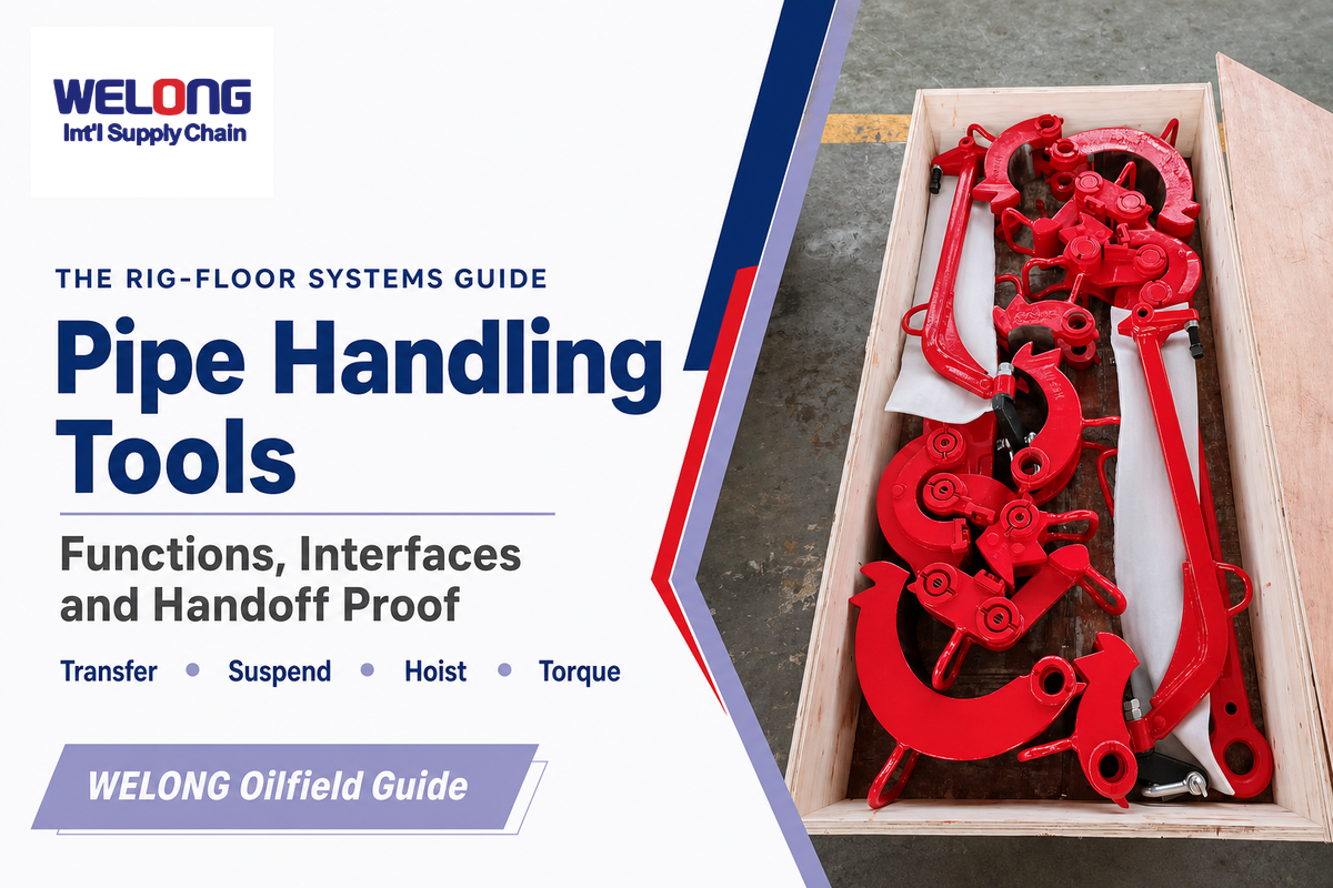
Oilfield Rig-Floor Guide
Trace the tubular from the pipe rack to the setback, separate each handling function, and preserve compatibility evidence at each handoff.
Pipe handling tools are rig-floor tools that transfer, position, suspend, hoist, grip, and rotate tubulars during drilling or servicing work. Catwalks transfer tubulars, rackers position them, slips suspend the string, and links and elevators carry the hoisting load. Tongs or roughnecks make and break connections. Considering all these jobs as one family of products conceals the places where a familiar setup can remain unverified.
This guide follows the complete rig-floor sequence. For tubular geometry and connection context before an interface review, see Welong’s drill pipe guide. It explains what must pass from one crew, machine, or tool to the next: identity, condition, intended function, physical fit, control state, and acceptance evidence. Product models, detailed capacity selection, pricing, delivery terms, and RFQ work remain on Welong’s pipe handling tools solution page. Detailed elevator mechanics remain in the casing, tubing, and drill pipe elevators guide.
Scope: use this article to structure a technical review. The applicable manufacturer instructions, controlled rig procedure, lifting plan, inspection program, and local legal requirements decide whether equipment may be used.
1. What “Pipe Handling Tools” Means on a Drilling Rig
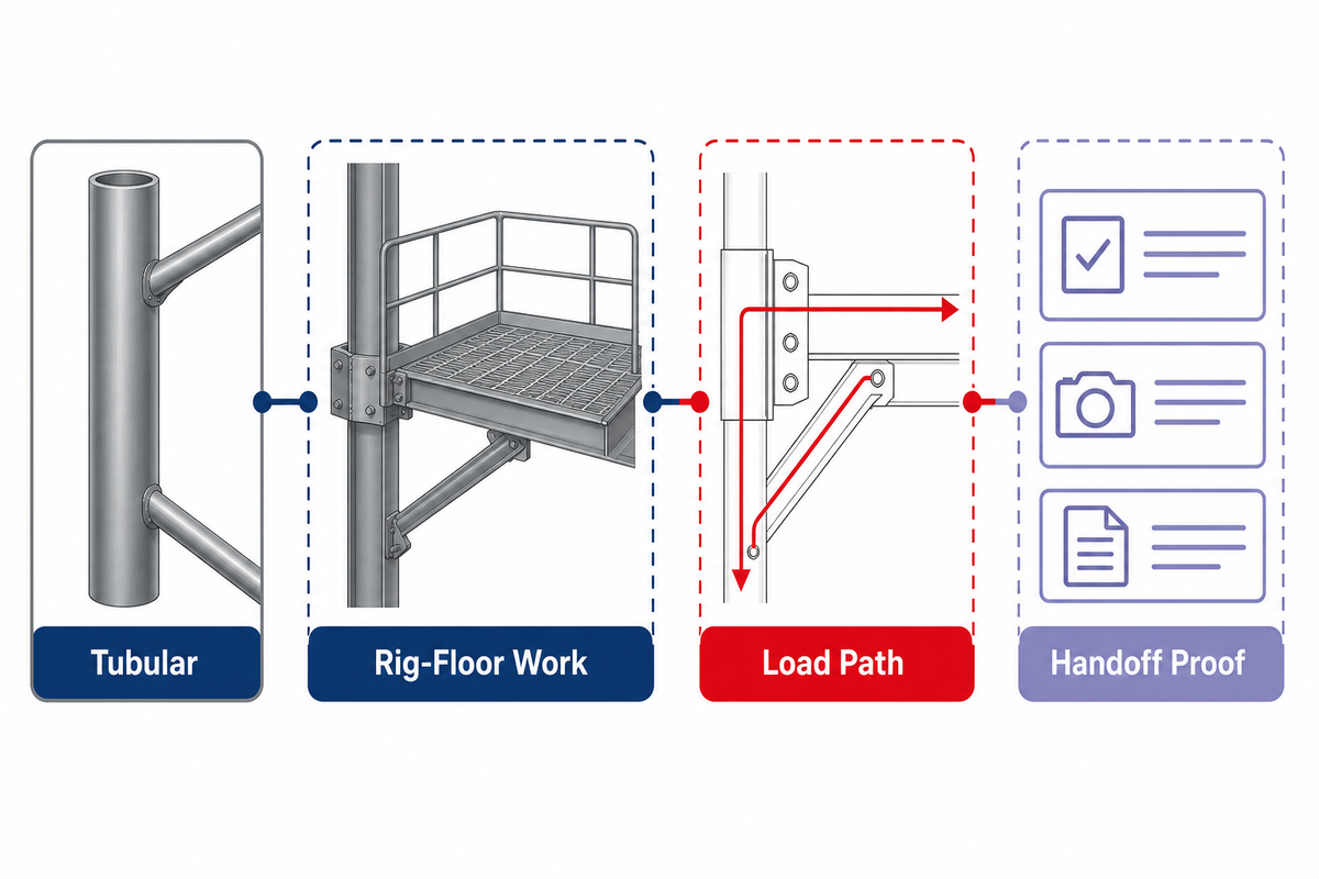
On a drilling rig, pipe handling tools transfer, position, suspend, hoist, grip, and rotate tubulars during drilling or servicing work. Calling these items tools describes the function, but doesn’t mean they’re interchangeable. Each function has its own load path, contact points, controls, and proof requirements.
That definition matters because web results for the same term cover pipeline construction, plumbing, fabrication, and warehouse material handling. A pipe stand used next to a trench doesn’t answer a rig-floor question about elevators, links, slips, tongs or rotary table. Searches for steel pipe handling tools, heavy duty pipe handling tools, and best pipe handling tools often mix field work, fabrication, and product listings; this guide uses those phrases only within the drilling-rig boundary. The rig context must appear in the first line of the requirement.
OSHA’s oil and gas hazard index treats drilling and servicing as work involving many types of equipment and materials. Its structure supports a system view: struck-by exposure, caught-between exposure, hazardous energy, machine movement, planning, and worker position overlap during a single tubular move.
Common mistake: starting with a catalog label such as “pipe tool” and then forcing the job into that label. Start with the task, tubular, load state, and next handoff.
Decision capsule: A 1-joint pick up and a 3 joint stand, as well as a suspended string, create different load conditions even when the nominal pipe size is the same. The state should be documented before identifying the member of the tool family. Reviewers can always ask if the item is being transferred, positioned, suspended, hoisted, or subjected to torque.
2. Follow the Tubular: Five Functions from Pickup to Setback
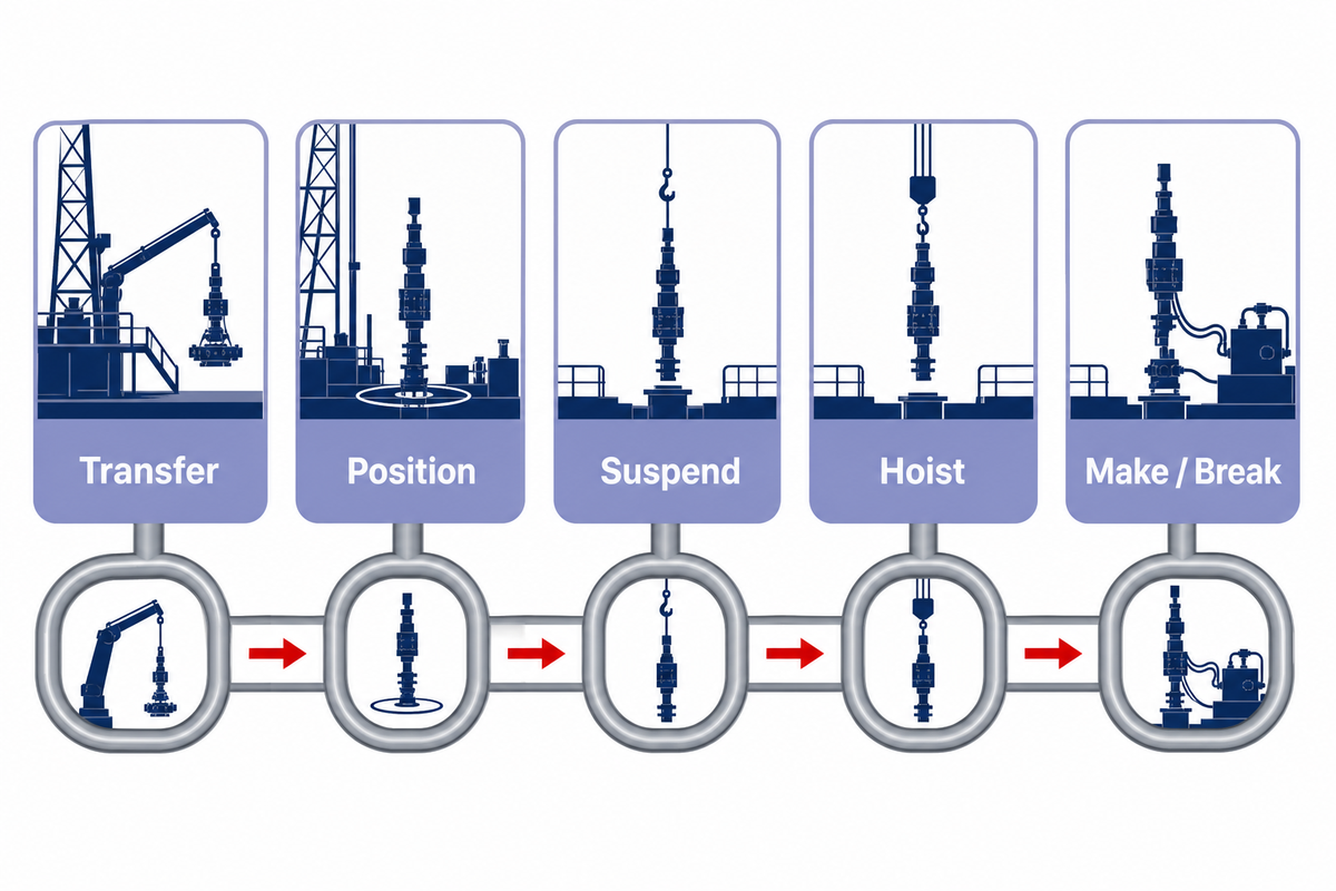
The Tubular Journey Map represents a normal activity on the rig floor and breaks it down into five functions: transfer, position, suspend, hoist, and make/break. The sequence can be in forward or reverse order, and several machine functions can overlap. The map helps focus on the key question: who’s the owner of the tubular’s weight and movement at this point?
1 · Transfer
Pipe rack to catwalk or drill floor
Pipe rack to catwalk or drill floor
2 · Position
Align with mousehole, well center, or setback
Align with mousehole, well center, or setback
3 · Suspend
Hold the string at the rotary or spider
Hold the string at the rotary or spider
4 · Hoist
Carry the tubular through elevators and links
Carry the tubular through elevators and links
5 · Make/Break
Grip and apply controlled torque
Grip and apply controlled torque
OSHA’s tripping task page lists slips, elevators, monkeyboard work, pipe breakout, and movement to the racking area as separate steps. It also identifies fall, overhead-object, pinch, crush, tong-swing, and communication hazards. The sequence shows why a correct tool-to-tubular fit doesn’t address all the issues related to the move.
Field scenario: during a trip out, elevators raise a stand while slips are set for the handoff. The stand then moves toward the setback. Tool lists may show all the required equipment, but they don’t show if slips have fully taken the string, if the elevator may open, if the setback path is clear, or if a derrickman is exposed above the floor. In this case, the state of the handoff is more important than how many pieces of equipment are involved.
| Point | Function | Typical owner | Evidence before release |
|---|---|---|---|
| 1 | Rack pickup | Gripper, sling, or handling arm | Correct tubular identified and retained |
| 2 | Catwalk transfer | Catwalk or conveyor | Travel path and end state confirmed |
| 3 | Floor presentation | Arm, crane, or crew | Exclusion zone and receiving device ready |
| 4 | Vertical positioning | Racker or handler | Orientation and control state known |
| 5 | Hoist connection | Elevator and links | Engagement and retention verified |
| 6 | String suspension | Slips or spider | Load transfer confirmed |
| 7 | Connection alignment | Handler or crew | Threads and centerline protected |
| 8 | Make/break | Tong or roughneck | Grip, backup, torque path, and swing zone known |
| 9 | Setback transfer | Racker, board, or crew | Receiving slot and worker position clear |
| 10 | Release | Outgoing device | Next support owns load and motion |
Decision capsule: a 27 m derrick position and a 0 m rig-floor position can place the same tubular inside very different exposure zones. Record worker position and overhead work beside each equipment handoff. Tool compatibility answers one part of the review; it doesn’t address fall or dropped-object exposure.
3. Hoisting and Suspension: Elevators, Links, Bails, Slips, and Clamps
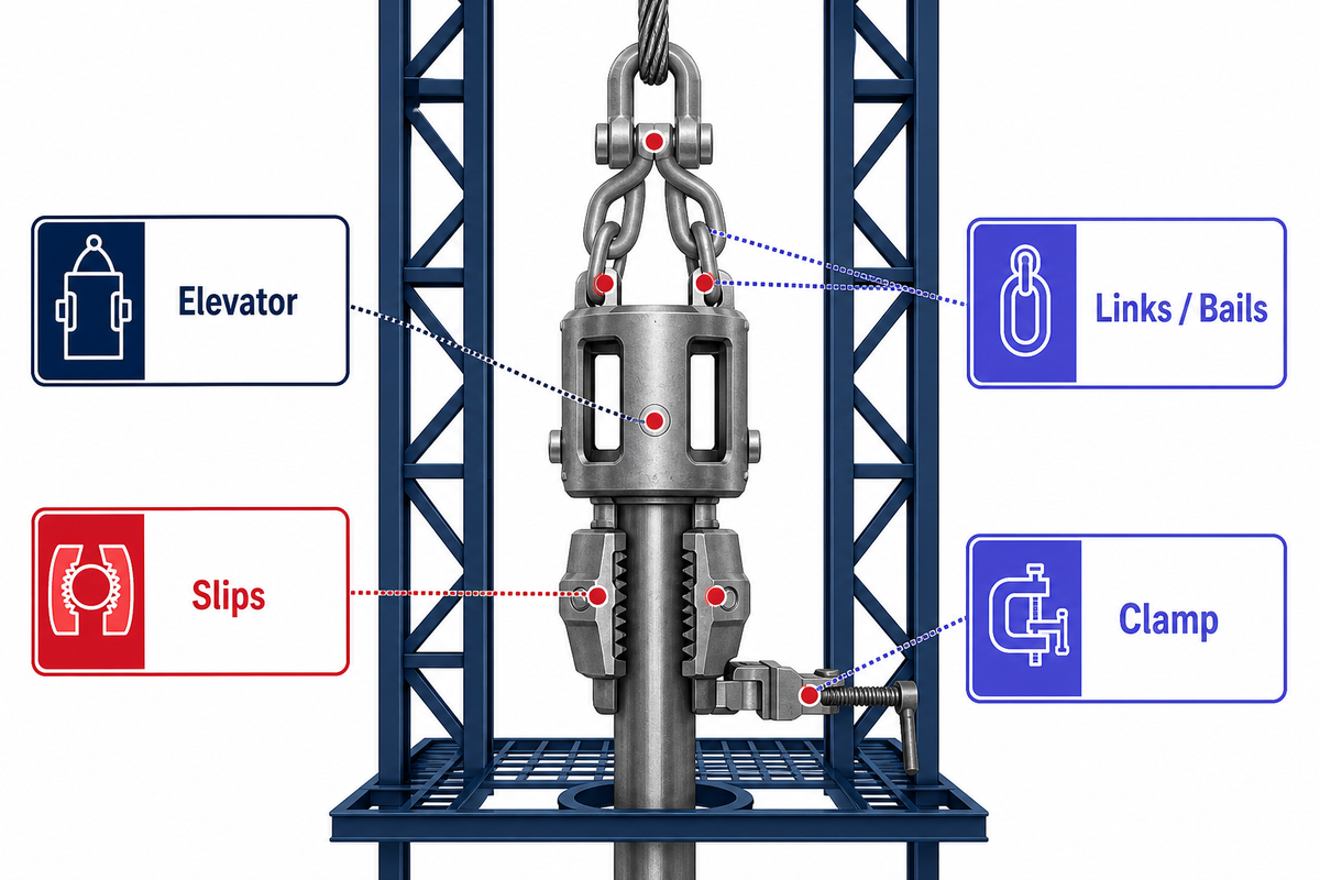
Hoisting tools raise or lower the tubular through the rig’s lifting path; suspension tools hold the string at the rotary table or spider while another connection changes. Elevators, links, and bails belong to the hoisting side. Slips, spiders, and selected clamps belong to a separate holding side.
Handoffs make the difference visible. The elevator can carry the string while the slips are out. The slips can then engage so the elevator can be unloaded and released. An interlock described in US7073598B2 aims to keep the tubular retained by at least one support during such a transfer. A patent documents a design concept; it doesn’t prove field performance or approve another system.
Links or bails also require their own identity, orientation, eye-to-ear fit, and pins or retainers. They also require a rating basis. Even a correct elevator doesn’t validate an unknown link. Likewise, a slip body which fits a rotary doesn’t prove the condition of the dies, inserts or tubular. The older Casing Slip Guides covers that holding family in more detail.
Stop the handoff: if neither side can show that it owns the load, or both sides assume the other has taken it, the state is unproven.
Decision capsule: treat 2 support states as explicit records: “hoisting path loaded” and “suspension interface loaded.” A release command needs proof that the receiving state is true. Rated capacity remains a separate check; it can’t stand in for engagement, retention, orientation, or current condition.
4. Torque and Positioning: Tongs, Roughnecks, Catwalks, and Racking Systems
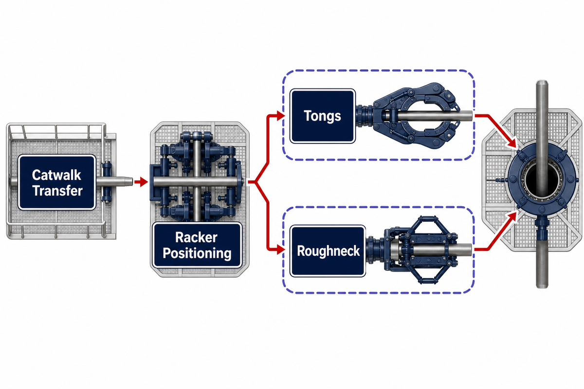
Torque equipment is the equipment that grips tubulars and helps make or break connections. Positioning equipment helps move tubulars to where another tool can receive them. Tongs and roughnecks are part of the torque path. Catwalks, cranes, handlers, and rackers belong mainly to the transfer or positioning path. Their roles can overlap but aren’t interchangeable.
Power tongs and iron roughnecks normally need a gripping interface, a backup reaction path, a defined swing or motion zone, and an approved torque process. Catwalk requirements include retention, travel limits, receiving alignment, and a clear transfer state. Racker requirements include gripping, position feedback, collision limits, and a known destination. Each piece of equipment creates a new evidence package at its outgoing boundary.
Many of the concerns named in OSHA’s tripping guidance, including tong swing, high torque connections, rotating equipment, communication, pinched hands and crushed feet, occur at the task level. A “machine is rated” statement at the task level doesn’t demonstrate control of the overall process.
| Tool type | Primary function | Main interface | Evidence question |
|---|---|---|---|
| Catwalk | Transfer | Rack to floor | Is the tubular retained through travel? |
| Pipe crane | Transfer | Deck to receiver | Are gripper and lift path verified? |
| Racking arm | Position | Well center to setback | Is destination state confirmed? |
| Elevator | Hoist | Tubular to links | Is support and latch engagement proved? |
| Links or bails | Hoist | Elevator to hook | Are fit, orientation, and retention correct? |
| Rotary slips | Suspend | String to rotary | Has load transfer completed? |
| Spider | Suspend | Tubular to deck support | Is gripping state positively known? |
| Manual tongs | Make/break | Jaw to tubular | Are die, line, and swing states acceptable? |
| Power tongs | Make/break | Grip and hydraulic drive | Are grip, backup, and controls matched? |
| Iron roughneck | Position + torque | Machine to connection | Are alignment and sequence interlocked? |
Decision capsule: A value in kN·m or ft·lbf is part of the make/break connection and path. A value in kN, short tons, or tonnes is part of a different path.
5. The Five-Interface Compatibility Map
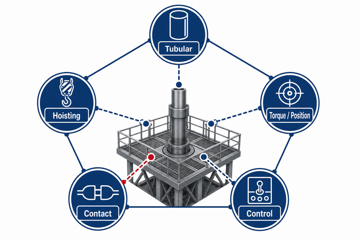
The Five-Interface Compatibility Map is a Welong editorial review framework. It breaks down tubular, contact, hoisting, torque or positioning, and control interfaces as separate sets of evidence. The map isn’t an American Petroleum Institute (API) or an Occupational Safety and Health Administration (OSHA) standard. Its goal is to identify unresolved handoffs prior to a product comparison or an operating decision.
5-Interface Compatibility Map
Mechanical interfaces, the operating environment, equipment location, and crew position should be in the same review record. The HSE view is especially important when a drilling operation moves between the rig floor, monkeyboard, catwalk and an offshore deck. The challenge is to preserve evidence ownership while the tubular changes hands.
| Recorded field | Example entry A | Example entry B | Required source |
|---|---|---|---|
| Tubular outside diameter | 127 mm | 114 mm | Controlled tubular record |
| Measured contact clearance | 3 mm | 5 mm | Approved interface drawing |
| Hydraulic pressure | 20 MPa | 2,900 psi | Manufacturer instruction |
| Transfer travel | 3 m | 2.5 m | Approved layout |
| Verified stop distance | 0.4 m | 400 mm | Site acceptance test |
| Alarm response | 0.1 s | 0.2 s | Control-system test |
| Handled mass | 2,000 kg | 4,409 lb | Lift plan |
| Rotational speed | 20 RPM | 30 RPM | Approved make/break procedure |
| Tool inclination | 15° | 30° | Equipment drawing |
| Ambient range | -20°C | 60°C | Equipment data sheet |
Use Note: All values in the table are format examples and shouldn’t be mistaken for operation limits or acceptance criteria. Replace all examples with the named, controlled values for the actual equipment, tubular and location. If a source doesn’t give a value, record the omission instead of taking a value from an example.
| Interface | Record | Check | Do not infer |
|---|---|---|---|
| 1. Tubular | Type, OD in mm or in, connection, upset, length, condition/history | Actual drawing and current item match | Nominal size proves every profile |
| 2. Contact | Shoulder, bore, insert, die, jaw, gripper, contact surface | Approved geometry and current condition | Capacity repairs a poor contact pattern |
| 3. Hoisting | Elevator, links, pins, retainers, hook, rating in kN or tonnes | Continuous load path and lowest-rated component | Each component’s mark proves the assembly |
| 4. Torque / position | Grip, backup, torque in kN·m, alignment, travel envelope | Reaction path and collision limits | A centered pipe is ready for torque |
| 5. Control | Mode, sensor state, interlock, alarm, stop, fallback, owner | Command and physical state agree | A green screen proves mechanical engagement |
Condition history is now in the first interface. Tubulars used in production may have defects, contamination and/or dimension questions that a fit check can’t answer. These questions should be directed to the operator’s material control and industrial hygiene process. Do not expand a normal handling-tool review into unsupported guidance for cleaning, cutting, welding, or reaming contaminated pipe.
Field scenario: A crew receives a tubular of the expected nominal OD, and the elevator closes. Tool-joint profile, link set, and latch condition are documented, but the tubular’s status tag is missing after a yard transfer. Mechanical interfaces may look correct. Interface 1 remains open because identity and condition history didn’t travel with the item. The review stops before load is applied.
Decision capsule: At least 5 interface decisions and 1 accountable owner for each open item should be captured. Dimensions in mm or in, loads in kN or tonnes, torque in kN·m, pressure in MPa, and control response in ms must be traced to the source document. Unit conversion doesn’t create missing approval.
6. Manual, Mechanized, and Automated Handling Change the Work, Not the Proof
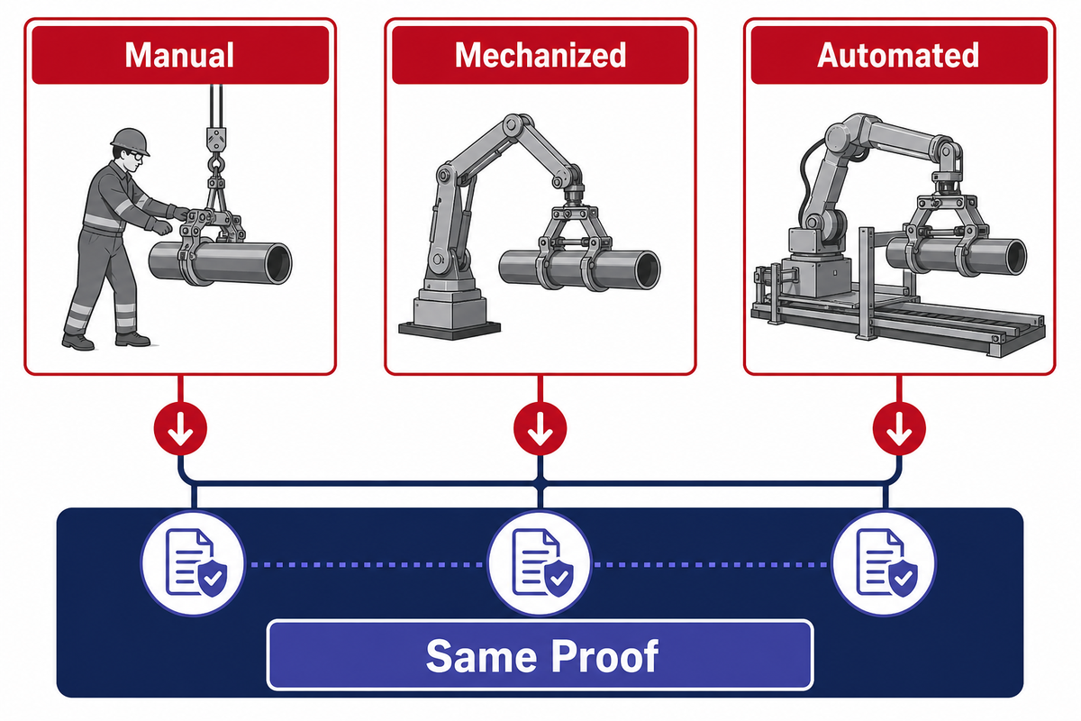
Manual, mechanized and automated systems distribute decisions and motion in different ways. Mechanization may relocate personnel from selected pinch, swing, or red-zone activities. Automation may integrate a number of machines. Neither of these changes the requirement to prove physical fit of components, tool condition, interlock state, fault recovery, position of personnel, and accountable acceptance.
A first-party ConocoPhillips case reports 400,000 m of tubular handled hands-free with 3 robotic arms across several recent Montney pads. That example shows how exposure can change when machines carry out repetitive movements. It doesn’t establish a universal reliability rate, approve another rig, or eliminate planning for abnormal states.
A separate Drillmec case described automatic pipe movement and make/break steps alongside sensor calibration, false alarms, software stability, crew training, and troubleshooting work. Its reported 25% overall efficiency gain, 27% contribution from tripping improvement, and 98% automatic-drilling reliability belong to that deployment. They shouldn’t become a fleet-wide promise.
CDC’s review of oil and gas extraction falls found 63 fatal falls during 2005–2014. Pipe handling immediately preceded 14 events (22%), and 22 workers (35%) fell from a derrick board. Many derrickmen worked up to about 90 ft (27 m) above the rig floor. Those historical findings explain why moving selected tasks away from height can matter, while the remaining machine and handoff risks still require control.
“The highest level of automation available may not always be best.”
| Level | Operator role | Proof that gains importance |
|---|---|---|
| Manual | Direct handling, positioning, latching, and communication | Body position, line of fire, hand placement, visual engagement |
| Mechanized | Remote command of one or more powered motions | Travel limits, visibility, mode ownership, emergency stop |
| Automated | Supervision, exception handling, reset, and authorization | Sensor coverage, sequence state, interlocks, alarm response, fallback |
Decision capsule: Compare automation projects with six evidence fields: exposure moved, sensors used, interlocks enforced, fault-recovery path, manual fallback, and training owner. The Drillmec result was measured over 4 years and can inform questions, but it cannot replace a site-specific acceptance test.
7. Pre-Use and Shift Handover: Keep the Proof with the Tool
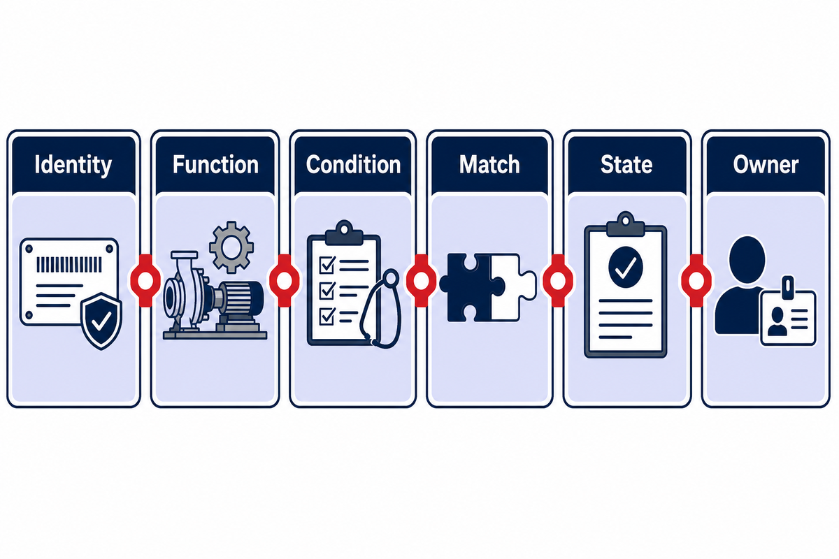
Before use, a strong review checks identity, condition, intended function, physical interfaces, control state, and current acceptance records. During handover to the next crew, the same evidence should be provided. Breaks in the “proof chain” occur, for example, when a crew only receives a verbal “it was fine” during a handover. Equipment may not have even moved during a shift.
Write the Interface-to-Interface Proof Chain in six lines:
- Identity: tool, tubular, insert, link, attachment, and control-mode identifiers.
- Function: transfer, position, suspend, hoist, make/break, or a defined combination.
- Condition: current inspection status, visible damage, open repairs, and quarantine.
- Match: drawing, manufacturer’s combination, approved setup sheet, or engineering record.
- State: loaded/unloaded, engaged/released, local/remote, automatic/manual, alarm/reset.
- Owner: a person or role allowed to accept the next handover.
Field Scenario: On a previous shift, a mechanized handler was cleared of an alarm and left in manual mode. The physical problem has been cleared, but the mode change and alarm code are unclear to the next shift. A command to execute a normal function now produces an unanticipated motion path. A 6-line handover should show the current mode, the reset performed, the open cause review, and the owner who must authorize return to automatic operation.
An IADC line-of-fire alert describes a crew manually latching a running tool while applying torque. When the tool detached, stored torque produced uncontrolled backspin and facial injuries. The event gives one clear handover lesson: the next action must be based on the real energy and engagement state, not the intended state.
Common mistake: using inspection date as a complete handover. A current inspection does not say whether the correct insert is installed, whether a control bypass is active, or whether a repair remains open.
Decision capsule: one missing identifier can invalidate a 6-line handover. Record dimensional values with units, alarm times in s or ms, pressures in MPa or psi, load/torque values, and source revision. “Same as last shift” isn’t traceable evidence.
8. Failure Signals at Handoffs, and When to Stop
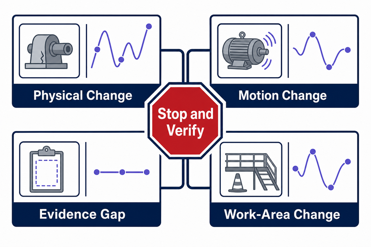
A stop signal is any observation that breaches confidence in the identity, condition, engagement, load ownership, motion control or the work area. The correct response is to hold the next transition and verify the affected interface. A general guide cannot convert those signals into universal discard limits or repair instructions.
Physical state
Incomplete latch, binding, misalignment, loose retainer, damaged contact surface, unexpected gap.
Incomplete latch, binding, misalignment, loose retainer, damaged contact surface, unexpected gap.
Motion state
Unexpected movement, drift, overshoot, collision warning, delayed stop, unexplained pressure loss.
Unexpected movement, drift, overshoot, collision warning, delayed stop, unexplained pressure loss.
Evidence state
Missing ID, unknown insert, unreadable mark, open repair, untraceable modification, conflicting inspection record.
Missing ID, unknown insert, unreadable mark, open repair, untraceable modification, conflicting inspection record.
Work-area state
Person in the red zone, overhead conflict, lost communication, obstructed view, unclear command owner.
Person in the red zone, overhead conflict, lost communication, obstructed view, unclear command owner.
OSHA’s tripping page tells crews to control tong swing, stand clear of the rotary table during rotation, use special procedures for high-torque connections, keep hands away from pinch areas, and maintain communication between floorhands and the driller. Those are task controls, not equipment discard measurements.
Numbers do matter if they’re from a controlled source. For a given design, a manufacturer may establish wear, pressure and clearance limits and proof-load or inspection levels. For a drilling program, alarm response times may be defined in s, hydraulic pressures in MPa, and an exclusion distance in m. Keep the number with the equipment ID and document revision.
Decision capsule: Stop at any unexplained change. Don’t wait for multiple signals to agree. The restart package should name the affected interface, observed condition, energy state, controlled procedure, reviewer, and evidence that closes the issue. If a repair is undocumented, it’s an open condition.
9. Standards, Markings, and Records: What Each Can and Cannot Prove
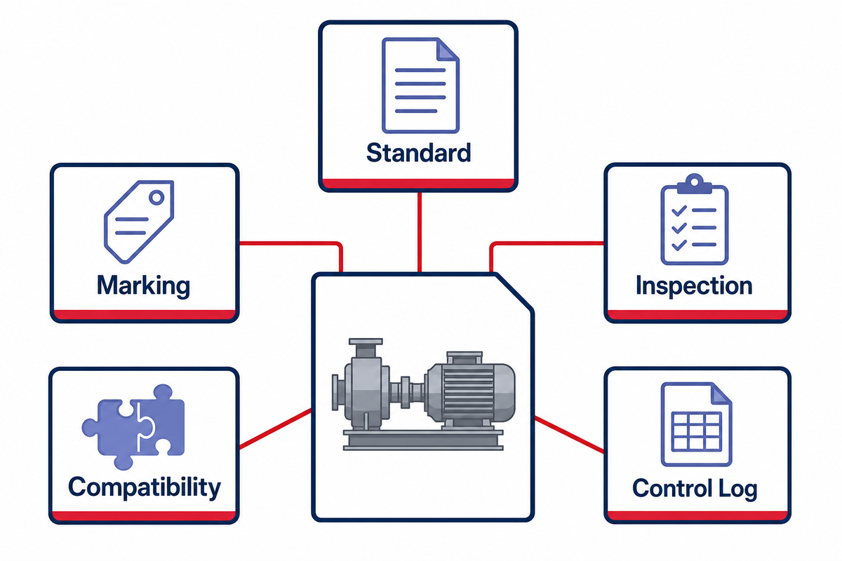
Standards define scopes and requirements; markings identify declared equipment attributes; inspection records document a condition review at a specified time. Each type of evidence may be needed to make a different decision. No single type of evidence supports a determination that a mixed assembly is correctly mated, currently serviceable, and has been accepted for the specific task now planned for the rig.
When this guide was researched, the official API latest-updates page listed an API 8C licensing-form update in July 2026 and a 6th Edition update notice in August 2025. Check the live page and the contractually applicable publication before use. An article can’t freeze the current edition for every jurisdiction or purchase order.
OSHA’s oil and gas standards index points to standards, directives, interpretations, and consensus material rather than one universal pipe-handler rule. Applicability depends on the work and jurisdiction.
“This standard does not cover … oil and gas well drilling and servicing.”
That exclusion is easy to miss because unexpected hydraulic, pneumatic, mechanical, and stored-energy hazards still exist on drilling and servicing equipment. Don’t describe the review method in this article as compliance with 29 CFR 1910.147. Use the site procedure and the requirements that actually apply to the operation.
| Evidence | Can support | Cannot prove alone |
|---|---|---|
| Applicable standard | Scope and specified requirements | Current condition or cross-component fit |
| Nameplate or marking | Identity and declared attributes | Authenticity, condition, or application approval |
| Inspection record | Observed condition at a stated time | Future condition or correct installation |
| Compatibility letter or drawing | Approved combination and revision | Condition of the actual items on the floor |
| Control-system log | Command, sensor, alarm, and mode history | Mechanical engagement unless independently sensed |
Decision capsule: attach 4 items to a high-consequence configuration: applicable requirement, equipment identity, current condition record, and assembly or site acceptance. If a document has a revision date, keep it. A mark like “API 8C” doesn’t answer a separate interface or current-condition question.
10. What Changes Next: Remote Operation, Sensors, and Automated Pipe Movement
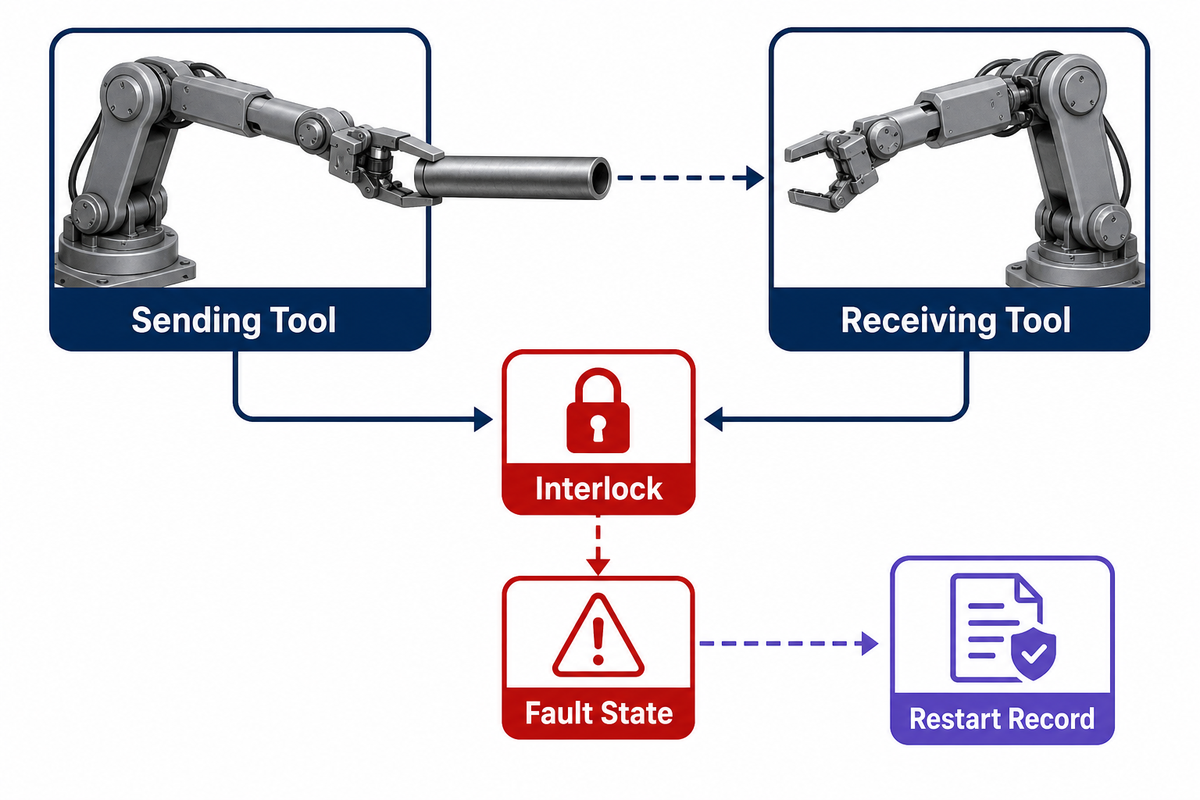
Pipe handling is developing toward remote operation, sensor-rich equipment, and coordinated handoffs. The relevant buying question isn’t whether a system is “automated.” The relevant questions are what is measured, interlocked, and transitioned; how faults are recovered; what the manual fallback position is; and who owns the record.
One patent illustrates an interlock principle: retain the tubular with at least one support, while another support changes state. More modern systems can incorporate this principle with position encoders, pressure feedback, latch sensors, collision zones, and sequence controls. Every signal requires a defined response to failure. Missing or contradictory signals shouldn’t be treated as a nuisance alarm.
Use the Interface-to-Interface Proof Chain in a technical inquiry. Ask the supplier to define every transfer, name the sending and receiving components, and list the sensed states. Then describe the interlock, define the safe fault state, document the restart path, and describe what evidence is transmitted to the next shift. This request generally gives better information than a general inquiry about the percentage of automation.
A practical RFQ boundary
Send the tubular list, operating sequence, five interface records, target rig layout, applicable documents, and preferred control level. Maintain price, delivery, model selection, and commercial terms on the pipe handling tools solution page.
Frequently asked questions
Are pipe elevators and pipe slips the same tool?
No. Elevators normally belong to the hoisting path, while slips or spiders suspend the string at the rotary or another support point. They come into play during a load handoff, but perform different functions.
Does a higher rated capacity make mismatched equipment acceptable?
No. Capacity is only one characteristic of a system. Tubular profile, contact geometry, latch or grip state, links, pins, controls, condition, and an approved combination still need evidence.
Can one checklist cover manual and automated pipe handling?
The five interfaces can be used to organize the review. The evidence differs. Automated systems add sensor coverage, interlocks, modes, alarms, fault recovery, software state, and fallback responsibilities.
Which standard applies to pipe handling tools?
The answer depends on the equipment family, task, contract, jurisdiction, and current edition. API 8C and API 7K cover different equipment scopes. Verify the live publication status and the controlled documents for the specific assembly.
What information should go to a supplier?
Provide tubular drawings, intended function, handling sequence, rig interfaces, load and torque basis, control level, applicable standards, inspection or documentation needs, and handoff-state evidence. Welong’s company profile captures the business and quality-support context.
References and Sources
- OSHA: Oil and Gas Extraction Hazards
- OSHA: Oil and Gas Extraction Standards
- OSHA eTool: Tripping Out/In
- OSHA: 29 CFR 1910.147
- CDC/NIOSH: Fatal Falls in Oil and Gas Extraction, 2005-2014
- API: Latest Monogram and APIQR Updates
- IADC Safety Alert 14-17
- Drilling Contractor: Process Automation Case
- ConocoPhillips: Montney Automated Drilling Rig
- Google Patents: US7073598B2 Tubular Makeup Interlock
Why Buyers Work With Welong
About Welong Engineering Support
China Welong supports oilfield buyers with engineered supply-chain service for drilling tools, well-control equipment, rig-floor tools, casting parts, and industrial forged components.
Project Review Before RFQ
We help buyers compare tool family, material route, API or ISO requirements, inspection records, supplier capability, delivery risk, and documentation needs before a purchase decision is finalized.
Request An Oilfield QuoteCompany Profile // Data Sheet
CompanyChina Welong International Supply Chain
BrandWelong
CountryChina
Business TypeOilfield tools and industrial supply-chain partner
Main ProductsDownhole drilling tools, fishing and milling tools, wellhead and well-control equipment, oilfield hoses, rig-floor handling tools, mill rolls, and forgings
Engineering CapabilityTool-family selection, specification envelope review, API / ISO reference support, material traceability, inspection coordination, and supplier-route comparison
RFQ Data NeededTool type, size, connection, rating, grade, standard, quantity, drawings, and delivery target
Websitewelongoiltools.com
![Casing, Tubing & Drill Pipe Elevators [Field Guide]](https://welongoiltools.com/wp-content/uploads/2026/09/casing-tubing-drill-pipe-elevators-guide-featured-768x512.png)