Get in touch with Welong Company

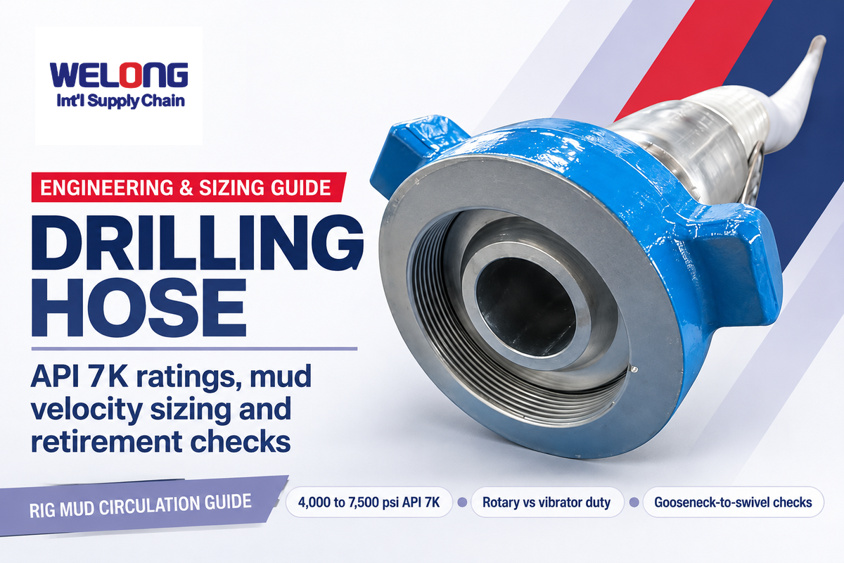
A Drilling Hose forms the high-pressure flexible link in an oil well rig’s mud circulation circuit, carrying abrasive drilling fluid from the static standpipe manifold into the vertically moving rotary swivel or top drive. While rigid steel standpipe lines handle fixed derrick runs, the flexible rotary hose accommodates continuous vertical travel and the mud pump vibrator hose isolates vibration, with each assembly qualified for its working pressure and pulsation duty.
This guide describes selection of pressure grades, determines bore velocity and performs field retirement checks for oil and gas drilling operations. For custom quotations and catalog tables, visit our commercial rotary and vibrator drilling hose solution page.
Updated November 2026 · By Karry
Quick Engineering Summary
Common API Spec 7K working pressure grades for steel-cable-reinforced drilling hose assemblies are 4,000 psi (Grade C), 5,000 psi (Grade D), or 7,500 psi (Grade E) working pressure. Rotary hoses connect the standpipe to the swivel, while shorter vibrator hoses isolate mud pump vibration between the pump manifold and standpipe manifold, with actual length determined by the rig layout. Every new assembly undergoes a factory hydrostatic proof test with water at 1.5 times rated working pressure, held for at least 15 minutes.
Key Engineering Takeaways
- API Spec 7K separates derrick rotary hoses and mud pump vibrator hoses from API Spec 16C choke and kill lines and API Spec 16D blowout preventer (BOP) hydraulic control lines.
- Factory acceptance testing uses water and holds 1.5 times rated working pressure for at least 15 minutes (11,250 psi on a 7,500 psi Grade E hose), whereas API RP 7L Addendum 2 caps required rotary hose field testing at 1.25 times maximum working pressure or the lower isolation valve limit and recommends a hold of no more than 10 minutes.
- In the 1,000 gallons per minute sizing example, stepping up from a 3-inch to a 4-inch inner diameter lowers calculated average mud velocity from 45.4 ft/s to 25.5 ft/s and the velocity-squared value by about 68 percent, with allowable flow set by the hose manufacturer.
- High-pressure drilling hoses use qualified factory couplings, including factory-swaged or built-in nipples, and field re-ending of worn hoses can compromise pressure integrity and original qualification.
What a Drilling Hose Does in High-Pressure Rig Mud Circulation
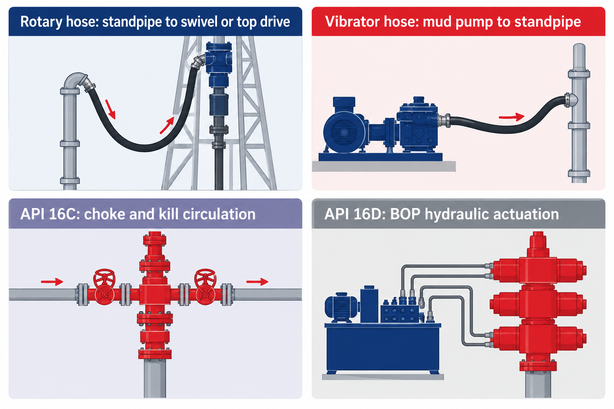
During oil drilling and hydrocarbon exploration, mud pumps draw conditioned drilling mud from suction pits and discharge it toward the rig floor. The U.S. OSHA drilling eTool glossary defines the standpipe as the rigid vertical pipe between the mud pump discharge line and the rotary hose. The swivel hangs from the traveling block, connects to the rotary hose and allows the drill string to rotate.
What is the difference between a Kelly hose and a rotary drilling hose?
A Kelly hose is a common name for a high-pressure rotary drilling hose that connects the standpipe gooseneck to the rotary swivel or top drive on a drilling rig, subject to assembly qualification under API Spec 7K. On older Kelly-drive rigs, the hose feeds drilling fluid through the swivel into a hexagonal or square Kelly bar; on modern top drive rigs, the rotary hose feeds the top drive gooseneck directly as the drill string travels up and down the mast.
While the long rotary hose hangs in a suspended hose loop in the derrick, a second API Spec 7K flexible assembly – the mud pump vibrator hose (also referred to as a shock hose in WorkSafeBC OHS Regulation Part 23) – spans the mud pump discharge manifold and the standpipe manifold. According to Continental Industry’s high-pressure drilling hose engineering guide, vibrator hoses are usually 9.1 meters (30 feet) or less in length and isolate mechanical vibration or accommodate alignment before fluid enters the derrick standpipe. Since the primary purpose of a vibrator hose is to accommodate alignment and isolate mechanical vibration of the pump, as opposed to controlling mast movement, rotary and vibrator hoses aren’t operationally interchangeable.
Engineers organizing oilfield hose families across rig fluid circuits separate mud-circulation hoses from well-control lines. Safe transmission of drilling mud from the surface manifold into the rotating string depends on correctly matching each line to its circuit duty. Once the fluid leaves the rotary hose and passes through the swivel, it flows down the drill pipe and exits the drill bit nozzles to cool the cutters and lift rock cuttings up the annulus. High-pressure wellbore kick circulation belongs to the API Spec 16C choke and kill lines, while hydraulic actuation of the wellhead blowout preventer stack belongs to the API Spec 16D control lines.
API Spec 7K Grades A–E, Temperature Classes and FSL Levels
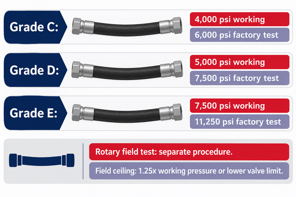
Purchase requisitions that request an “API 7K hose” don’t define the key engineering variables. Under the American Petroleum Institute specification API Spec 7K ( Drilling and Well Servicing Equipment ), flexible mud lines are classified by pressure grade, temperature range, and Flexible Specification Level (FSL). Every new assembly is required to pass its factory hydrostatic pressure test prior to shipment.
What do API 7K Grade D and Grade E mean on a drilling hose?
API Spec 7K Grade D working pressure is 5,000 psi (34.5 MPa) with a factory hydrostatic test at 7,500 psi (51.7 MPa), while Grade E is rated 7,500 psi (51.7 MPa) and tested at 11,250 psi (77.6 MPa). The 1.5-times working pressure proof test is distinct from minimum burst design factors of 2.5-to-1 for mud hoses and cement hoses below 10,000 psi, and 2.25-to-1 for cement hoses at 10,000 psi or higher.
Besides pressure grade and temperature class, buyers specify the Flexible Specification Level (FSL1 for rotary and vibrator hoses in normal service, FSL2 when high-frequency pressure pulsations above 1,000 psi amplitude are likely, and FSL 0 for cement hoses). In published manufacturer’s datasheets such as Continental’s API 7K Rotary and Vibrator Hose specifications and Copper State Rubber’s API 7K Certificate No. 7K-0014 datasheet the listed heavy-duty rotary and vibrator assemblies are qualified to FSL1 or FSL2, with pressure grades and temperature ranges to be verified for the specific assembly.
API 7K Grade-to-FSL Verification Matrix
The API 7K Grade-to-FSL Verification Matrix compares API Spec 7K pressure grades, 1.5x factory proof pressures for covered hoses, API RP 7L rotary field test ceilings before any lower isolation valve limit, and FSL requirements or service notes for eight hose categories.
| Hose Grade / Duty Class | Max Working Pressure | Factory Test Pressure (API 7K rows: 1.5x WP, water, at least 15 min) | RP 7L Rotary Field Test Ceiling (1.25x WP, subject to lower isolation valve limit) | Typical FSL and Qualified Rig Application |
|---|---|---|---|---|
| API 7K Grade A | 1,500 psi (10.3 MPa) | 2,250 psi (15.5 MPa) | 1,875 psi (12.9 MPa) | FSL 1 or FSL 2 / rotary and vibrator hoses |
| API 7K Grade B | 2,000 psi (13.8 MPa) | 3,000 psi (20.7 MPa) | 2,500 psi (17.2 MPa) | FSL 1 or FSL 2 / rotary and vibrator hoses |
| Slim-Hole Rotary Hose | 3,000 psi (20.7 MPa) | Verify model-specific factory test pressure (psi / MPa) | Verify applicable field procedure and pressure limit (psi / MPa) | Midwest Hose SHR-64-3K slim-hole rotary service for mobile and coring rigs |
| API 7K Grade C | 4,000 psi (27.6 MPa) | 6,000 psi (41.4 MPa) | 5,000 psi (34.5 MPa) | FSL1 or FSL2 / rotary and vibrator lines |
| API 7K Grade D | 5,000 psi (34.5 MPa) | 7,500 psi (51.7 MPa) | 6,250 psi (43.1 MPa) | FSL 1 or FSL 2 / rotary and vibrator hoses |
| API 7K Grade E | 7,500 psi (51.7 MPa) | 11,250 psi (77.6 MPa) | 9,375 psi (64.6 MPa) | FSL 1 or FSL 2 / rotary and vibrator hoses |
| Top-Drive Dragchain Hose (assembly-specific qualification) | Verify assembly working pressure (psi) | Verify assembly factory test pressure (psi) | Verify applicable field test limit (psi) | Offshore top-drive dragchain loops; verify FSL if applicable |
| High-Pressure Cementing Hose | 10,000 or 15,000 psi by bore | 15,000 or 22,500 psi respectively | See OEM cementing procedure separately | FSL 0 / cement hoses only |
Engineering boundary: API Spec 7K’s 1.5x hydrostatic test pressure (such as 7,500 psi on Grade D and 11,250 psi on Grade E) is a factory acceptance test for newly manufactured mud and cement assemblies, held in water for at least 15 minutes; when required, in-service rotary hose field testing follows API RP 7L Addendum 2 with a ceiling of 1.25x maximum working pressure or the lower isolation valve limit and a recommended hold of no more than 10 minutes. Also note that API Spec 7K governs rotary and vibrator hose assemblies, whereas API Spec 7-1 governs metallic rotary drill-stem elements such as drill collars, kellys, and subs.
Three-Layer Drilling Hose Construction: Liner, Steel Cable and Cover
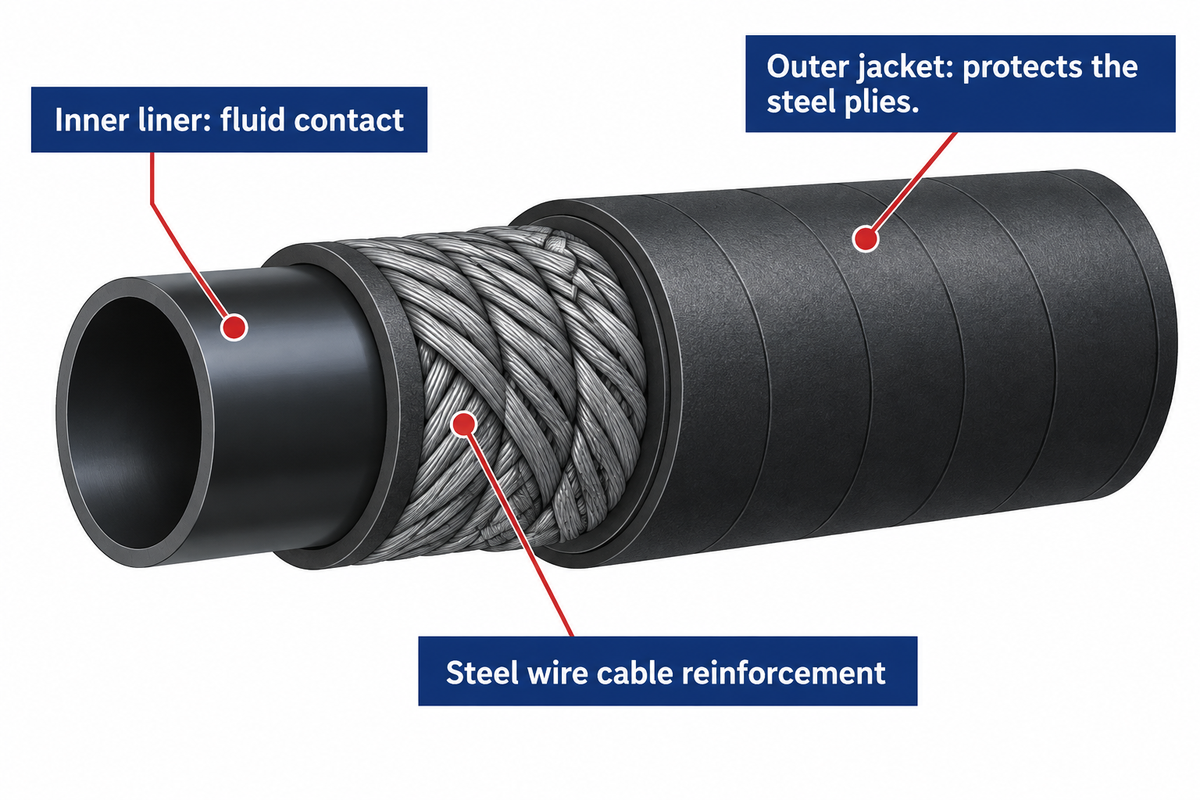
A rotary drilling hose is a bonded composite vessel that must contain internal mud pressure while flexing through repeated swivel or top-drive travel. To achieve both flex and burst strength, a hose wall uses three functional groups: liner, reinforcement and cover, with additional layers depending on the design.
- The innermost rubber liner contacts high-velocity drilling fluid loaded with barite weighting agents, fine silica sand, drill bit cuttings, and emulsified hydrocarbons. Gates’ Black Gold oilfield hose specification documents a black Type C Nitrile (NBR) inner tube compound shared with its Grade D and Grade E Rotary and Vibrator hoses, with -40°F to +180°F (-40°C to +82°C) listed for the ABS Mud and Oil product, whose nitrile tube is thickened to resist abrasion. As RIGRS’s API hose technical overview notes, oil-based mud applications can use compatible rubber blends such as NBR or hydrogenated nitrile (HNBR), and the manufacturer should verify inner liner suitability for the actual fluid and temperature and specify a separately qualified assembly for hydrogen sulfide (H2S) gas service or likely well-effluent exposure.
- Over the inner tube, some designs use 2 to 6 layers of high-tensile spiral wire reinforcement, with brass- or zinc-coated steel wire rope cables embedded in cushion rubber in Continental’s bonded construction. For spiral-wound steel cable plies, verify the model’s reinforcement construction and qualification for triplex pump impulse surges, with Grade D and Grade E assemblies rated for 5,000 psi and 7,500 psi working pressure respectively.
- A vulcanized synthetic rubber outer jacket shields the steel wire plies from external exposure and derrick rubbing, with resistance to ultraviolet sunlight and salt spray depending on the cover compound. Each elastomer compound offers a distinct performance characteristic in surface circulation, and the outer cover improves durability against abrasion and harsh rig weather.
Engineering boundary: For the Black Gold ABS Mud and Oil transfer hose with a Type C Nitrile inner tube, Gates cautions against transferring refined petroleum products like gasoline; verify fluid compatibility separately for rotary drilling hoses.
Matching Working Pressure to Mud Pump Surge
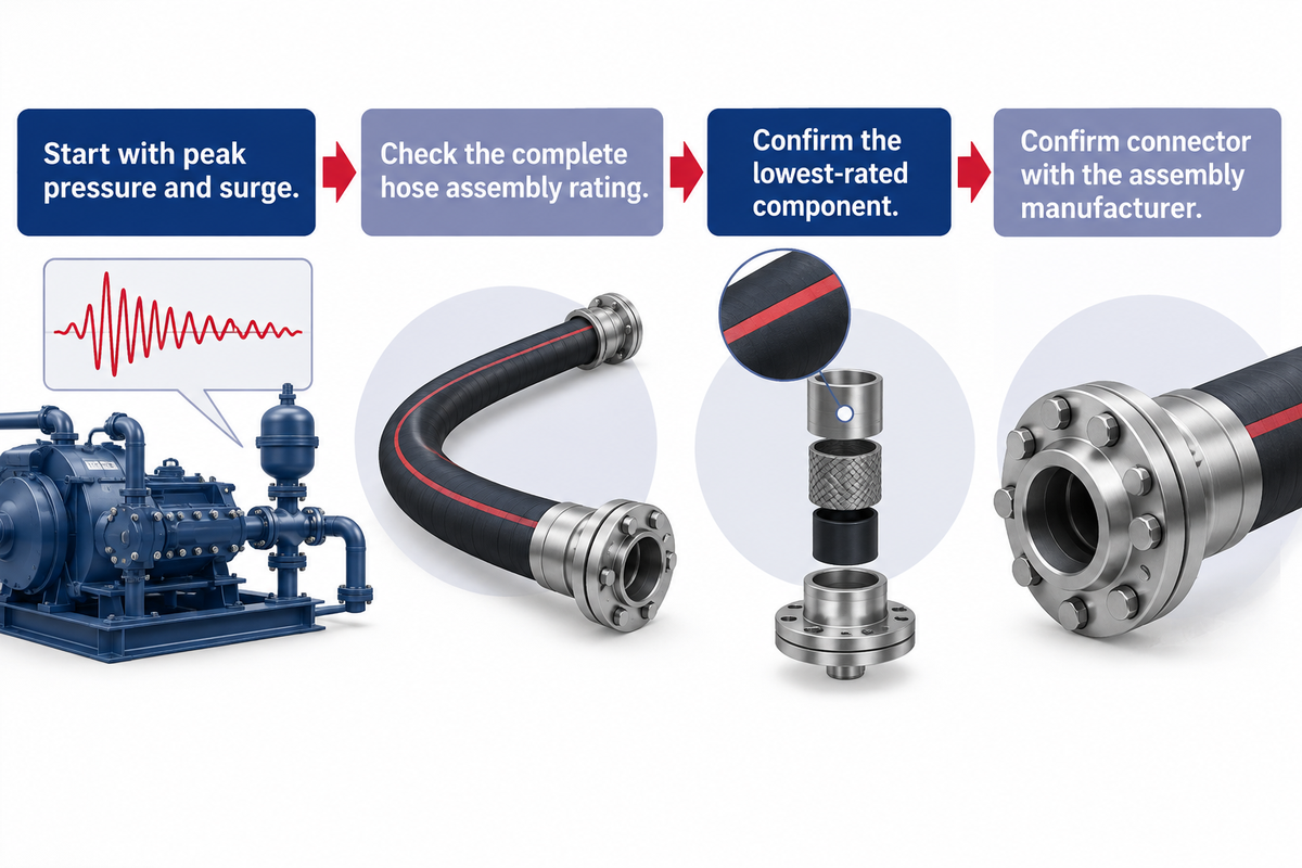
Selecting a drilling hose solely from average standpipe pressure can miss peak loads from cyclic mud pump pressure spikes or changes in operating conditions. A triplex piston pump can generate pressure pulsations superimposed on mean circulation pressure, so keep the peak pressure within the assembly’s rated working pressure to protect the hose and end couplings.
Field development reported by IADC’s Drilling Contractor on continuous circulation MPD subs describes an original design goal of up to 5,000 psi standpipe pressure for the continuous circulation sub to keep mud flowing across drill-pipe connections. While matching the hose pressure class to the rig pump capacity, the drilling engineers use three selection boundaries:
- Grade C (4,000 psi WP / 6,000 psi Factory Test) and a Slim-Hole assembly rated at 3,000 psi WP are separate options, with workover service requiring separate qualification checks and peak pressure, including surge, kept within the selected assembly’s rated working pressure.
- Grade D (5,000 psi WP / 7,500 psi Factory Test) can serve a qualified mud circulation duty when peak pressure including surges stays within the complete hose assembly’s 5,000 psi working pressure.
- Grade E (7,500 psi WP / 11,250 psi Factory Test) can serve a qualified mud circulation duty when peak mud pressure including surge stays within the assembly’s 7,500 psi working pressure, whereas when well cementing requires 10,000 psi to 15,000 psi pumping pressure, Continental’s drilling hose portfolio routes that duty to dedicated High-Pressure Cementing Hoses, with acidizing served by a separate fluid-compatible assembly.
Remember that the manufacturer’s rated working pressure for a complete hose assembly cannot exceed the allowable working pressure of its lowest-rated pressure-containing component. For a 7,500 psi Grade E hose, have the assembly manufacturer specify a suitable end connector and a butt-welded or integral attachment to the hose coupling.
Inside Diameter Sizing (2" to 5" ID), Mud Velocity and Bend Radius
What determines burst pressure is different from what determines the internal mud velocity, frictional standpipe pressure loss and abrasive wear on the liner. Common catalogue examples of API Spec 7K rotary and vibrator hoses have nominal bores from 2 inches (50.8 mm) up to 5 inches (127.0 mm), with 3-inch, 3-1/2-inch, and 4-inch IDs available in multiple grades.
How do you size a rotary drilling hose for flow rate and bend radius?
To size a rotary drilling hose, select an inside diameter that accommodates peak pump output within the manufacturer’s published flow limit, and choose an overall length that maintains the specified minimum bend radius throughout swivel travel, including the highest and lowest swivel positions.
Worked Mud-Velocity Calculation at 1,000 US GPM Circulation
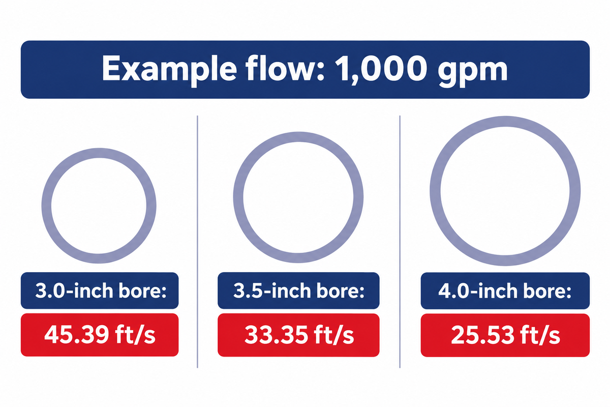
Using the standard hydraulic continuity equation v = 0.4085 × Q / d² (where v is average fluid velocity in feet per second (ft/s), Q is pump flow rate in US gallons per minute (gpm), and d is hose inside diameter in inches) compare three API 7K Grade E (7,500 psi) rotary hose bores at the illustrative flow of Q = 1,000 gpm, subject to each manufacturer’s published limit:
- For a 3.0-inch inside diameter (d = 3.0 in), v = 0.4085 × 1,000 / 9.0 = 45.39 ft/s; high velocity and abrasive solids can shorten hose life, with actual wear dependent on the fluid and hose configuration.
- For a 3.5-inch inside diameter (d = 3.5 in), v = 0.4085 × 1,000 / 12.25 = 33.35 ft/s, cutting fluid velocity by 26.5 percent compared with a 3.0-inch bore.
- For a 4.0-inch inside diameter (d = 4.0 in), v = 0.4085 × 1,000 / 16.0 = 25.53 ft/s; because kinetic energy per unit mass scales with velocity squared, stepping up from 3.0-inch ID to 4.0-inch ID reduces the velocity-squared value at the same pump flow.
Engineering boundary: The continuity equation calculates cross-sectional average velocity; actual standpipe parasitic pressure drop depends on drilling fluid rheology (plastic viscosity and yield point), total hose length, and gooseneck entry losses.
Alongside bore velocity, installation layout must respect the manufacturer’s minimum bend radius (MBR) measured to the centerline of the hose loop. Copper State Rubber’s API 7K rotary hose specification lists a 36-inch (3.0-foot / 0.91 m) minimum bend radius on sizes 4-inch ID and below, while SGPE’s published API 7K dimensional tables list minimum bend radii by hose size in inches and pressure grade for their rotary hoses. For hydraulic modeling context see the Eng-Tips flexible-pipe hydraulic calculation discussion; for installation, API RP 7L calls for sufficient vertical and horizontal span so the hose never bends tighter than its rated minimum radius near the end couplings.
Integral End Connections: Swaged vs Built-In Nipples and Hammer Unions
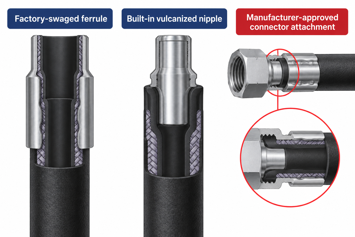
At 5,000 psi to 7,500 psi working pressure across a 4-inch bore, hydrostatic end-thrust attempts to eject the end coupling fittings with tens of thousands of pounds of axial force. Ordinary industrial band clamps or unqualified field-attachable reusable hydraulic fittings are unsuitable for rotary drilling service.
Instead, API Spec 7K drilling hoses use permanently attached factory hose couplings, with swaged and bonded couplings as two documented designs:
- In factory-swaged (crimped) steel couplings, as disclosed in U.S. Patent US7338090B2 (High pressure reinforced rubber hose swage or crimped coupling), the hose end may be skived to expose the high-tensile steel wire reinforcement, and a swaging press radially forms the outer ferrule over the wire plies while the internally expanded steel stem nipple helps lock them in a wave pattern.
- In built-in vulcanized full-flow nipples, the steel nipple and reinforcement cables are bonded directly into the hose carcass in the Continental design, and the vulcanized termination retains a smooth, full-bore internal passage.
Rig-end terminations can include API line pipe threads, hammer unions, flanges or hubs, with the attachment to the hose coupling butt-welded or integral above 5000 psi working pressure. Under UK Health and Safety Executive (HSE) Safety Bulletin FOD 4-2014, during replacement or maintenance, use matched and compatible hose and fittings per original equipment manufacturer specifications and treat verification as a pressure test. Cutting back a service worn rotary drilling hose in a field shop to re-crimp a saved coupling presents a coupling blow-off and fluid injection hazard because re-ending can compromise pressure integrity and original assembly qualification.
Drilling Hose vs Vibrator, Choke & Kill, Cementing and BOP Hoses
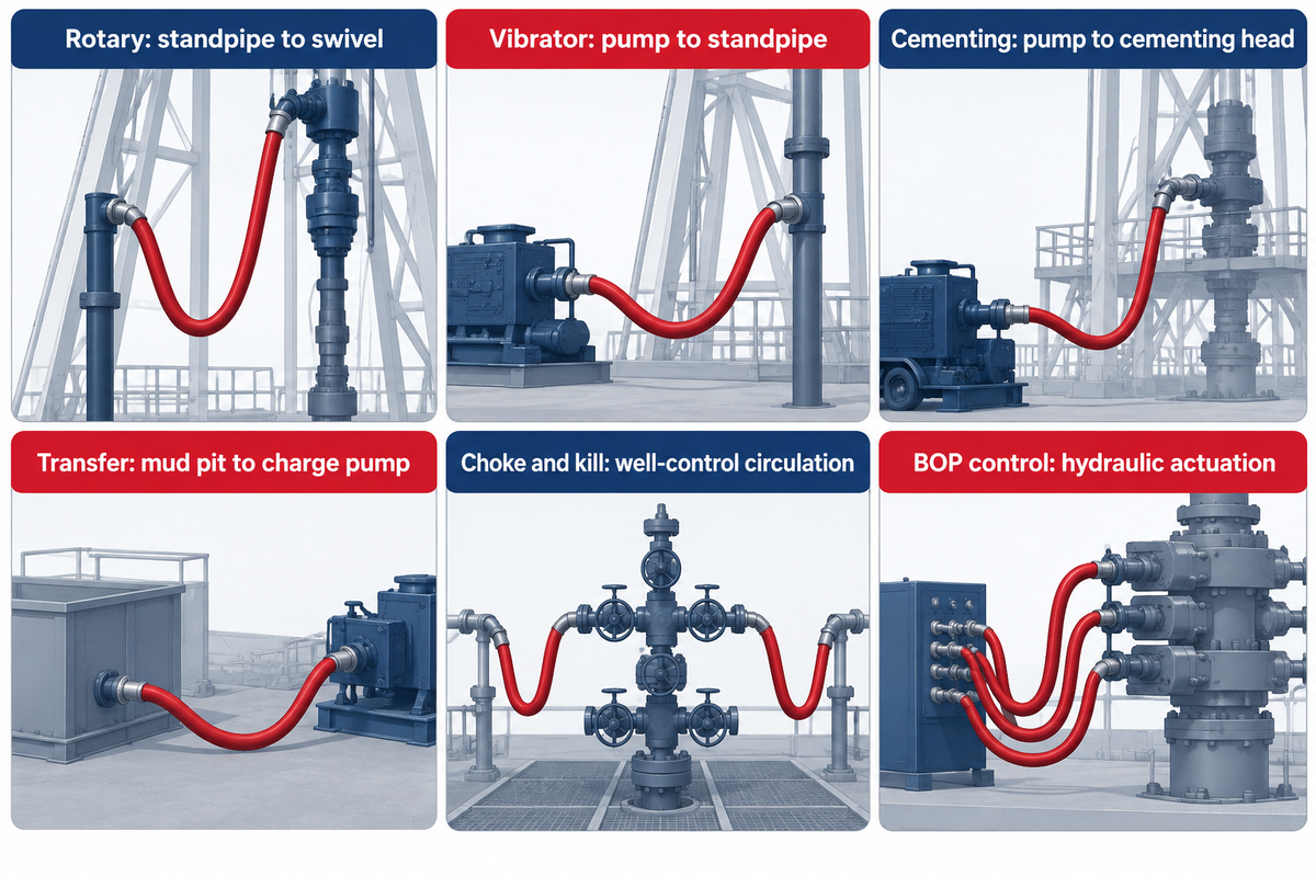
For multi-line rig equipment tenders that group high-pressure flexible conduits together, procurement teams must verify each application and keep mud circulation hoses separate from qualified sour gas well control lines. As summarized in RIGRS’s API hose comparison and ZMTE’s API 7K selection guide, each rig circuit needs its applicable API specification and qualification for the intended service.
| Rig Hose Type | Governing Standard | Circuit Location | Typical Bore & Length | Working Pressure & Primary Duty |
|---|---|---|---|---|
| Rotary Drilling Hose (Kelly Hose) | API Spec 7K (FSL1 / FSL2) | Standpipe gooseneck to rotary swivel or top drive | Verify ID by grade, length by travel and bend radius | 4,000 to 7,500 psi (Grades C–E); continuous abrasive mud circulation & vertical travel |
| Mud Pump Vibrator Hose (Shock Hose) | API Spec 7K (FSL1 / FSL2) | Triplex mud pump discharge manifold to standpipe base | Verify ID by grade, length by manifold routing | 4,000 to 7,500 psi (Grades C–E); isolates pump vibration & accommodates manifold alignment |
| Top-Drive Dragchain Hose | Verify API Spec 7K (FSL1 / FSL2) applicability for the specific assembly | Top-drive service loop inside a dragchain | Assembly-specific ID and dragchain loop length | Assembly-specific working pressure (psi) and bend radius for guided service-loop travel |
| Slim-Hole Rotary Hose | OEM specification; verify applicable API Spec 7K qualification | Slim-hole mast gooseneck, subject to model qualification | Verify model-specific ID and length (ft) | Verify model-specific working pressure (psi) for the slim-hole rotary assembly |
| High-Pressure Cementing Hose | API Spec 7K / OEM Cementing | Cementing pump truck/skid to rig floor cementing head | Verify ID by grade and length by cement line routing | 10,000 or 15,000 psi by bore; cement slurry for well cementing |
| Mud Booster and Suction Hose (separate duties) | OEM Oilfield Transfer / OEM Booster qualification | Mud pit to charge pump or subsea riser booster line | Verify bore and length separately for suction and booster service | 300 psi transfer example (Gates Black Gold 300SD) / separate model rating for Continental Mud Booster |
| Choke and Kill Hose | API Spec 16C (FSL2 covers high-temperature exposure) | BOP stack outlets to choke manifold | Verify model-specific ID and length for the well-control circuit | 5,000 to 15,000 psi; well control with assembly-specific high-temperature, H2S and fire qualifications |
| BOP Hydraulic Control Hose | API Spec 16D; verify LR OD/1000/499 fire qualification where required | Accumulator (Koomey) unit to BOP stack pods/rams | Verify ID and length for custom manifold runs | Verify working pressure for the hydraulic control fluid and the assembly’s required flame test duration and temperature |
If your project bill of materials includes well control lines, check our API 16C choke and kill hose assemblies, commercial API 16D BOP control hose assemblies, and BOP hose engineering and fire test guide to verify that each circuit is qualified by the applicable API specification.
Rig Floor Installation: Gooseneck Alignment, Twist and Safety Clamps
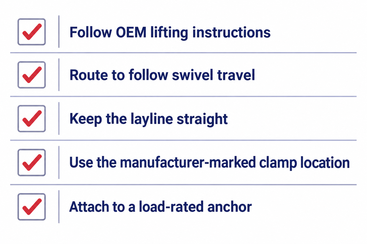
Rotary drilling hoses can be damaged during uncrating and derrick rigging. Kinking a heavy hose over a fork tine can damage the carcass, and axial torsion introduced during hammer-union make-up can damage the steel reinforcement when the hose is later pressurized or flexed.
To maintain hose integrity from the standpipe to the swivel during installation, rig crews use four main mechanical rigging practices:
- For yard transportation and derrick rigging, follow the manufacturer’s instructions to unpack the hose from its shipping reel or crate without dragging it across sharp steel, and lift the hose into the derrick with manufacturer-specified lifting equipment and points clear of the middle of the rubber body, using wide fabric web slings where the manufacturer approves them.
- Match the downward angle of the standpipe gooseneck (15° off vertical toward the swivel’s line of travel) to the natural hang of the catenary loop so the hose doesn’t bend sharply right behind the rigid coupling ferrule.
- Check the painted longitudinal branding stripe (layline) running along the outer cover while making up a hammer union or flange joint so the stripe stays straight and wing-nut hammering doesn’t twist the steel cable reinforcement.
- Install factory-supplied safety clamps on all rotary, vibrator, and jumper hoses at the manufacturer’s marked clamp locations per API RP 7L guidance and applicable rules such as WorkSafeBC OHS Regulation Part 23, anchoring the chain or wire-rope snubbing restraints to structural points capable of withstanding their breaking force.
Failure Modes and the Gooseneck-to-Swivel Retirement Matrix
Drilling contractors wonder if a rotary hose that passed a periodic water pressure test is safe to use in another deep well. As documented in the U.S. Bureau of Safety and Environmental Enforcement (BSEE) pressure-test frequency research report (TCP 5010), the BOP analysis of routine hydrostatic pressure tests concerns pressure-test frequency for blowout preventer equipment. In addition, published API RP 7L Addendum 2 field-test guidance (see API field-test procedure and limits and the supplier’s oilfield hose test summary) applies when a rotary hose field test is required under the approved site procedure, with test pressure capped at 1.25 times the hose maximum working pressure or the lower applicable isolation valve limit confirmed with the valve manufacturer (for example, 9,375 psi is the hose ceiling on a 7,500 psi Grade E hose) and a recommended maximum hold of 10 minutes. For a service-aged rotary hose, the factory 1.5x test pressure exceeds the field pressure limit in API RP 7L Addendum 2.
Engineering boundary: Static hydrostatic pressure tests can confirm that a hose contains the specified pressure under the test conditions. A pressure hold alone cannot establish remaining NBR/HNBR liner thickness after mud erosion or the remaining flexural fatigue life of the reinforcement.
Gooseneck-to-Swivel Retirement Matrix
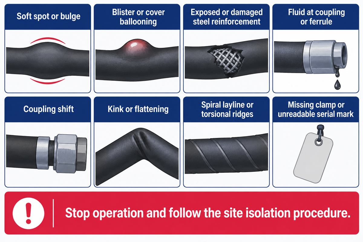
The Gooseneck to Swivel Retirement Matrix shows eight defect conditions, what to check and the immediate rig maintenance actions for an API Spec 7K rotary or vibrator hose.
| Inspection Zone / Defect Symptom | Physical Failure Indicators to Check | Immediate Rig Maintenance Action |
|---|---|---|
| 1. Gooseneck Soft Spot or Bulge. Inspect the section downstream of the nipple. | Inspect for possible inner liner wear and exposed wire plies near the mud inlet. | Stop mud pumps and remove the hose from service immediately under the site isolation and depressurization procedure; assess the liner, cover and coupling with the manufacturer. |
| 2. External Blisters or Cover Ballooning Along Body | Visually examine the inner surface of the hose liner. | Quarantine the assembly and keep external blisters intact, then arrange qualified full-length liner inspection after known exposure to pressurized gas and reject the hose if inspection finds liner bulges, blisters, punctures or other breaches. |
| 3. Exposed, Fractured or Rusted Steel Reinforcement Cables | Inspect the outer cover for external rubbing, dropped-object impact and any resulting breach. | Remove the hose from service for documented manufacturer assessment and disposition because moisture can corrode high-tensile cables and reduce burst margin. |
| 4. Mud Weeping at Ferrule Shoulder or Tell-Tale Vent Hole | Check the stem-to-liner seal, wire reinforcement and swaged or built-in coupling for possible damage. | Isolate and depressurize the circuit under the site procedure, then remove the hose from service; never attempt to re-crimp or weld a leaking coupling in the field. |
| 5. Axial Coupling Shift or Exposed Bare Hose Carcass Behind Ferrule | Check for evidence of ferrule grip slippage or tensile over-pull after isolation. | Immediate removal from service under the site isolation procedure for suspected coupling displacement, pending OEM disposition. |
| 6. Permanent Kink, Flattening or Sub-MBR Bend Deformation | Hoisting damage or operation below the specified minimum bend radius warrants qualified inspection. | Remove the hose from active circulation for assessment without re-pressurizing it to restore its shape. |
| 7. Spiral Layline Stripe Displacement or Torsional Ridges | Possible make-up twist locked into the hose during hammer-union tightening. | Isolate the hose and bleed pressure under the site procedure; remove the hose from service for qualified inspection if twist or spiral ridges are observed. |
| 8. Missing or Slipped Safety Clamp or Illegible Assembly Identifier | Loss of whipping restraint at the manufacturer’s marked clamp location or loss of hydrotest traceability. | Suspend pumping and follow the site isolation procedure until the OEM-rated safety clamp, rated snubbing restraint and serial records are inspected. |
While patent filings such as U.S. Patent US9562822B2 consider the use of conductive reinforcement layers for remote electronic continuity monitoring of hose wear, follow the manufacturer’s controlled physical inspection process for API Spec 7K drilling hoses and record the results in a digital asset log such as Continental’s C-IQ electronic hose register.
Do (Rig Maintenance Best Practices)
- Flush rotary and vibrator hoses with the manufacturer’s approved fluid when specified by the manufacturer or site procedure.
- Install factory-supplied safety clamps at the manufacturer’s marked locations and secure compatible chain or wire-rope snubbing restraints to structural anchors rated for their breaking force.
- When rotary-hose field tests are required under API RP 7L Addendum 2, cap pressure at 1.25x maximum working pressure or the lower applicable isolation-valve limit confirmed with the valve manufacturer and follow the recommended maximum hold of 10 minutes.
Don’t (Critical Safety Prohibitions)
- Never strike or tighten a hammer union wing nut or approach a weeping ferrule while the standpipe manifold is pressurized.
- Never cut back a damaged API 7K drilling hose to re-crimp a salvaged coupling in the field.
- Never lift a rotary hose with a sling hitched around the middle of the rubber carcass.
RFQ Specifications, Traceability Package and Supply Chain Sourcing
For a separate marine application, see Oilfield Technology’s June 2025 special report on choosing the right hose; for drilling hose assemblies, verify coupling qualification and liner performance for the actual fluid and temperature. When international contractors supply drilling packages to remote rigs, incomplete test paperwork can stall site acceptance. Rather than relying on generic per-foot catalog estimates, buyers confirm bore diameter, Grade D or Grade E as applicable, liner chemistry for the intended service and integral hammer-union details where used in a 6-point technical RFQ:
- Specify the exact API Spec 7K duty class, Rotary Drilling Hose or Mud Pump Vibrator Hose, along with Flexible Specification Level FSL1 for normal service or FSL2 for high-frequency pressure pulsation as applicable, and verify the specification separately for any Top-Drive Dragchain Hose.
- State the nominal inside diameter sized for mud flow velocity in an available pressure grade, together with the coupled overall length for rig routing, swivel travel and minimum bend radius.
- Define the pressure grade and factory proof test pressure: Grade C (4,000 psi WP / 6,000 psi test), Grade D (5,000 psi WP / 7,500 psi test), or Grade E (7,500 psi WP / 11,250 psi test).
- Select the temperature class (Range I, II, or III) and verify the manufacturer’s inner tube elastomer compatibility for oil-based mud and high-temperature service, and specify a separately qualified assembly for H2S sour gas service or likely well-effluent exposure.
- Detail the qualified factory coupling, its attachment method, and the matching rig-side end connections with size, pressure rating, seal, union figure or thread identification where relevant, and NACE MR0175 sour-service metallurgy for applicable wetted metallic end-fitting components where required.
- Confirm the published minimum bend radius for the selected hose and require safety clamps at the manufacturer’s marked locations with rated chain or wire-rope snubbing restraints.
Engineering boundary: Company-level ISO 9001:2015 or API Spec 7-1 certificates cover quality management systems and metallic rotary drill-stem elements (such as drill collars, kellys, and subs); they do not constitute an API Spec 7K monogram license for a flexible hose assembly. Founded in 2001, China Welong (Welong Oil Tools) is an international integrated supply-chain service provider whose drilling-tool quotations identify the manufacturing route for buyers to verify applicable ISO 9001:2015 and API Spec 7-1 scope, with a product and sourcing scope that includes BHA drilling tools, borehole enlargement tools, impact tools, wellhead equipment, handling tools, and oilfield hose packages.
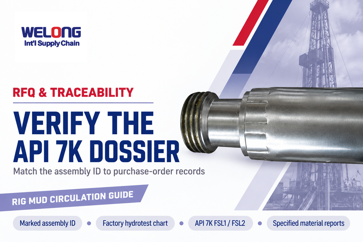
Before releasing any rotary or vibrator hose shipments for rig mobilization, use our interactive hose documentation and paper-trail builder to identify the records to request and verify the marked serial number, on the ferrule where the manufacturer uses that marking location, against the agreed assembly-specific 1.5x hydrostatic test chart, API Spec 7K FSL1/FSL2 records, manufacturer’s statement of compliance and specified material test reports (MTRs). To request a quote or a custom assembly drawing, visit our drilling hose assemblies and custom API 7K specifications page.
Engineering Takeaway & RFQ Review
Specify every rotary and vibrator drilling hose by its complete hydraulic and mechanical envelope: applicable API Spec 7K grade and working pressure, FSL1 or FSL2 design qualification, bore sized within the manufacturer’s mud flow limit, liner compatibility matched to mud chemistry, and qualified factory couplings, with a serialized 1.5x hydrostatic test chart specified in the purchase order.
Frequently Asked Questions
Are rotary drilling hoses and mud pump vibrator hoses interchangeable?
No; rotary hoses accommodate mast travel, whereas vibrator hoses connect the pump and standpipe manifolds.
No, rotary drilling hoses and mud pump vibrator hoses are not interchangeable even though both are built under API Spec 7K. Rotary hose length depends on full vertical top-drive or Kelly travel in the derrick, whereas vibrator hoses are shorter flexible connections between the mud pump discharge manifold and the standpipe manifold that accommodate alignment and isolate vibration.
What is the difference between a rotary drilling hose and a BOP hose?
API 7K rotary hoses circulate abrasive drilling mud at 4,000–7,500 psi for Grades C to E where listed, while API 16D BOP hoses carry hydraulic control fluid.
An API Spec 7K rotary drilling hose is a steel-cable-reinforced conduit with catalogue examples from 2-inch to 5-inch inner diameter that circulates abrasive drilling mud from the standpipe gooseneck to the rotary swivel, with 4,000 to 7,500 psi working pressure in Grades C to E where available for the specified bore. An API Spec 16D BOP hose is a smaller hydraulic control line that transmits accumulator fluid to close the blowout preventer stack, with specific models such as Gates Black Gold BOP assemblies fire-tested at 1,300°F (704°C) for 5 minutes.
Why is it risky to re-end or re-crimp a used drilling hose?
High-pressure API 7K couplings are attached at the factory; field re-ending risks compromising pressure integrity.
High-pressure API Spec 7K drilling hoses use factory-built couplings qualified with the hose design, with swaged and vulcanized designs as examples. Cutting back a service-aged hose and pressing on a replacement ferrule can compromise the complete hose assembly’s pressure integrity and original qualification, creating a severe coupling blow-off and fluid-injection hazard under mud pump pressure.
How is an API 7K drilling hose hydrostatic proof test performed?
New assemblies hold 1.5x rated working pressure with water for at least 15 minutes at the factory; required rotary field tests cap at 1.25x MWP or the lower applicable isolation valve limit, with a recommended hold of no more than 10 minutes.
Every new API Spec 7K rotary and vibrator hose undergoes a factory hydrostatic test with water at 1.5 times rated working pressure for at least 15 minutes (11,250 psi on Grade E), while API RP 7L caps required rotary hose field tests at 1.25x MWP or the lower applicable isolation valve limit and recommends holding no more than 10 minutes.
How do you choose the right oil drilling hose for a rig?
Match API 7K pressure grade, bore size to the manufacturer’s mud flow limit, liner compatibility, bend radius, and end connections.
Start by matching the API Spec 7K pressure grade, Grade C (4,000 psi), Grade D (5,000 psi), or Grade E (7,500 psi), to your maximum triplex mud pump discharge pressure including surges and select an inside diameter that keeps peak gallon-per-minute circulation within the manufacturer’s published flow limit. Next, verify the manufacturer’s inner liner chemical resistance for the operating fluid and temperature, including oil-based mud, and require a separately qualified assembly for sour gas exposure, confirm the catenary loop length respects minimum bend radius throughout top-drive travel, and specify matching pressure-rated rig connectors and request the applicable FSL1 or FSL2 design qualification records.
What is the purpose of safety clamps on a rotary drilling hose?
Safety clamps and rated chain or wire-rope snubbing restraints restrain the hose from whipping if a pressurized coupling fails.
Safety clamps mounted at the manufacturer’s marked locations and anchored with rated chain or wire-rope snubbing restraints secure both hose ends to limit whipping if a coupling parts.
What traceability documents should accompany an API 7K drilling hose shipment?
Verify the API 7K statement of compliance and request a tag-matched 1.5x hydrostatic test chart and any specified material test reports.
For each high-pressure drilling hose assembly, verify the API Spec 7K statement of compliance, specify in the purchase order an assembly-specific factory hydrostatic proof-test chart recorded at 1.5 times working pressure and any required material test reports, and match the marked serial number, pressure grade, temperature range and Flexible Specification Level (FSL1 or FSL2) against the records. Procurement engineers should audit these serialized assembly records rather than relying on general company ISO 9001 or API Spec 7-1 drill-stem certificates.
Do you need engineering support to match a replacement rotary or vibrator hose assembly to your rig’s standpipe manifold and mud pump package? Contact China Welong’s supply-chain engineering team for your bore size, pressure grade, end connection drawing and the required FSL design qualification records.
This engineering guide provides an understanding of public occupational safety regulations (US OSHA, WorkSafeBC, UK HSE), BSEE pressure-test research on blowout preventers, published patent filings, and named manufacturer product specifications (Continental, Gates, Copper State Rubber). Illustrative continuity velocity calculations demonstrate hydraulic sizing principles and don’t replace rig-specific rheological modeling. Company background is provided by China Welong.
References & Sources
- U.S. Occupational Safety and Health Administration (OSHA), Oil and Gas Well Drilling and Servicing eTool Glossary (Standpipe & Swivel)
- WorkSafeBC, Occupational Health and Safety Regulation Part 23: Oil and Gas (Rotary and Shock/Vibrator Hose Safety Restraints)
- UK Health and Safety Executive (HSE), Safety Bulletin FOD 4-2014: Hydraulic Injection Injury and Matched Hose Fittings
- U.S. Bureau of Safety and Environmental Enforcement (BSEE), Pressure Test Frequency Research Report (TCP 5010)
- Drilling Contractor (IADC), Continuous Circulation in MPD Applications up to 5,000-psi Standpipe Pressure
- Oilfield Technology, Choosing the Right Hose for Oil and Gas Operations (June 2025)
- U.S. Patent US7338090B2, High Pressure Reinforced Rubber Hose Swage or Crimped Coupling for Skived Rotary Drilling Hose
- U.S. Patent US9562822B2, Flexible Contact Arrangement for Hose Assembly with Conductive Reinforcement Monitoring