Get in touch with Welong Company
Cement Head: A Practical Guide to Functions, Types, and Selection

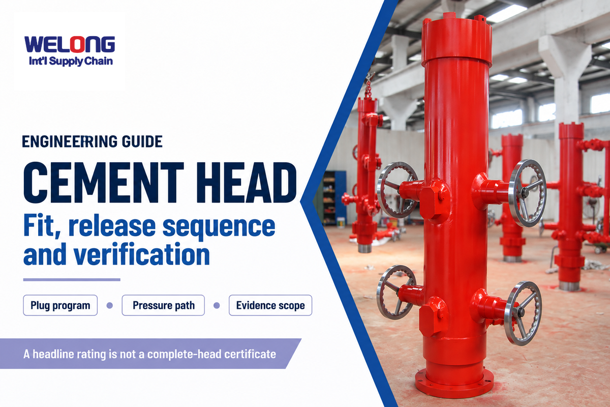
A cement head is a surface fitting at the top of a casing or running string to hold and release cementing plugs while connecting the pumping path to the string.
The more difficult element is evidence-based fit. An indicator doesn’t prove that a plug reached the float collar. An API thread name doesn’t certify the assembled head. These differences and others are the basis of the selection and verification steps in this manual.
Quick answer: Five elements determine the fit of a cement head. Select a cement head by five gates: the string interface, the plug program, the required pipe movement, the release/indication method, and the service envelope of the complete connected assembly. Then substantiate every critical claim with a drawing, procedure, test record, certificate, or current license of the named owner.
What this guide helps you decide
- Where the head sits in the cementing system and what it does not replace.
- How single plugs, double plugs, casing, drill-pipe, top-drive, rotating and remote features interconnect.
- Which observations require a stop, isolation, and escalation as called for in the approved program.
- What documentation provides system configuration, traceability, pressure evidence and scope of credentialing.
How a Cement Head Fits the Cementing System
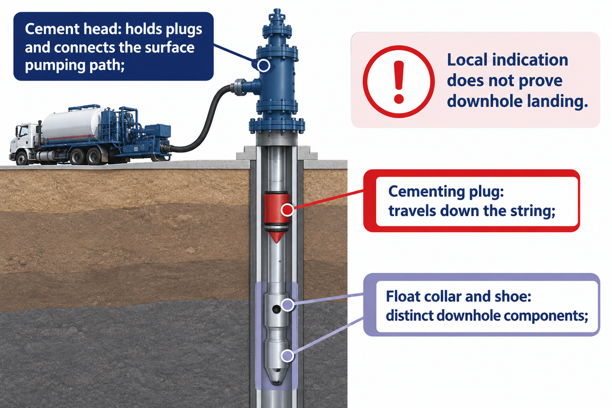
A cement head is the surface connection of the cementing lines and casing or drill-pipe string. The SLB Energy Glossary defines it as a device on the top casing joint that holds a cement plug before it’s pumped down the casing. Most heads intended for a conventional two-plug job can hold both the bottom and top plugs, while an incorporated manifold provides the circulation-line connection.
A casing cement head and a drill pipe cement head share this working principle, but they connect to different string arrangements. So, the head must be coordinated with well design and the exact casing or drill string interface it will be installed on.
With that position, the head has three functions that are interconnected. The first function is to hold a plug or plugs before release. The second function is to provide a flow path that contains pressure. The last function is to provide an interface for pumping. The exact device may add retainers, valves, a plug-passage indicator, a swivel, lifting features, remote release, or a top-drive connection. These changes don’t affect the basic system boundary.
The head is not the cementing plug. The plug travels down the string. The head is not the float collar or float shoe where the plug may land. The head is also not the pumping unit that mixes and delivers the slurry and is also not the complete cementing manifold or all high-pressure lines connected to the job. Considering all these as the “cementing head system” could conceal who owns the various interfaces and what document(s) establishes the ratings.
This limitation is critical to diagnosing an event. A pressure change at the surface may involve the head, a valve, a line, a connection, the string, or the downhole flow path. An indicator can record a local passage and not prove downhole landing. The safest first question to ask, therefore, shouldn’t be “Which part failed?” The right questions to ask should be: what was observed, where was it observed, and what record or approved check can confirm the next state?
Cement Head Components and the Plug-Release Sequence
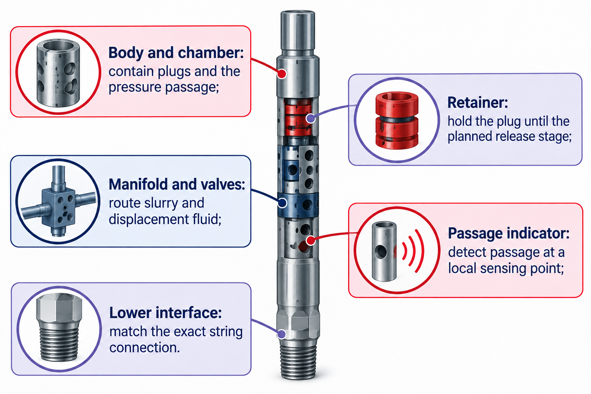
A typical casing head is made up of a body that has one or two plug chambers, retaining or release assemblies, manifold connections, valves, and sometimes a mechanical passage indicator. The bottom connection joins the head to the running string or casing. The top or side connections join the pumping path. The offered drawing should identify each pressure-containing boundary and the exact mating connection.
| Component | Primary function | Evidence to check |
|---|---|---|
| Body and chamber | Contains the plug and pressure passage | Drawing, chamber dimensions, material and design rating |
| Retainer/release assembly | Holds the plug until the planned release stage | Compatible plug dimensions and model procedure |
| Manifold and valves | Routes slurry and displacement fluid | Flow schematic, line interfaces and assembly rating |
| Passage indicator | Responds when a plug moves past a local sensing point | Indicator states, inspection record and approved confirmation method |
| Lower interface | Connects to the string | Thread/gauge record or approved connection drawing |
The top plug eventually lands on the bottom plug and is associated with the planned bump response. This is a functional explanation, not a valve-turning procedure. Loading positions, release mechanisms, valve alignment, pressure limits, confirmation methods, and contingency steps belong to the exact head manual and the approved job procedure. They cannot be transferred safely from a generic article or another manufacturer’s drawing.
In a traditional two-plug sequence, the bottom plug is released prior to cement slurry. Depending on the approved program, it can be released prior to, or after the spacer has been pumped. As it travels down the casing, the bottom plug separates the cement slurry from the fluid ahead of it. Under the approved program, its diaphragm ruptures after the bottom plug reaches the float collar, allowing the slurry to continue down the casing and into the annulus for cement placement. The top plug follows the cement slurry and separates it from displacement fluid.
Downhole, the float collar and shoe contribute different functions from the head at surface. Cement placement moves slurry through the casing and into the annular space between casing and the wellbore; a restriction or obstruction along that path must be interpreted within the approved program rather than from the surface device alone.
Indicator boundary
Passage indicators show that a plug passed the sensing point in the head. Record the local indication and use the approved confirmation chain for the next conclusion.
Types of Cement Heads and How to Select One
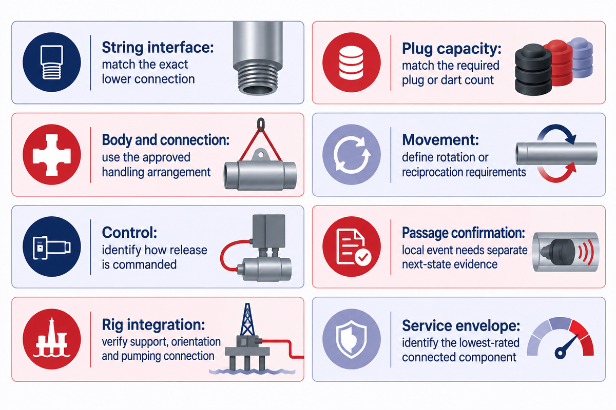
The so-called “types” of cement heads are more intuitive when described as overlapping selection axes. A cement head may be a double-plug casing head with a clamp connection. Another can be a single-plug drill-pipe head with a swivel. A top-drive head may be remotely operated and rotating. Describing all classes of equipment with a single flat list creates erroneous either/or situations.
| Selection axis / type | Common options | Decision question |
|---|---|---|
| String interface | Casing / tubing work string / drill pipe | What string and exact lower connection must the head fit? |
| Plug capacity | Single / double / multi-plug system | How many plugs or darts must be loaded and released? |
| Body/connection design | Integral / clamp / quick-change / liftable | Which approved interface and handling arrangement applies? |
| Movement | Stationary / rotating / reciprocating | Must the string rotate or reciprocate during conditioning or cementing? |
| Control | Manual / pneumatic / hydraulic / remote | How is release commanded and positively identified? |
| Passage confirmation | Local mechanical / electronic / remote indication | Which local event is indicated, and what separate evidence confirms the next state? |
| Rig integration | Conventional lift / top-drive / swivel arrangement | How will the head be handled, oriented, supported, and connected to the pumping path? |
| Service envelope | Configuration-specific | What is the lowest-rated connected component in the stated service? |
The strongest correction is simple: plug capacity and pressure rating are separate design decisions. A single-plug head isn’t necessarily low pressure. A double-plug head isn’t necessarily high-pressure. The working pressure belongs to the exact model, size, material, connection arrangement, and complete configured assembly.
Product examples illustrate the scope of design options. Argus lists casing heads in single- or double-plug arrangements, conventional or top-drive, and drill-pipe single-plug heads, with product-specific pressure ratings up to 10,000 psi.
Remote and rotating configurations are real, but this source establishes only a remote configuration. Drilling Contractor, Aug. 2025 stated a remote five-plug stage-cementing operation for a 9-5/8-inch casing run in Saudi Arabia. The case demonstrates a project-specific remote configuration.
A buyer should describe the operating requirement before requesting a type name. For example, if rotation isn’t required, a rotating head may complicate the design without addressing the governing requirement. If two plugs must be loaded in the head, a single-plug chamber can’t be made suitable by a higher pressure rating. If the lower connection doesn’t match the approved string interface, the rest of the specification can’t rescue the mismatch.
Treat “tubing cement head” as a work-string and interface requirement, not as a universal catalog class. Consider that configuration only when the approved cementing method uses a tubing work string and the offered head or adapter drawing matches the string connection, plug or dart program, service envelope, handling arrangement, and operating procedure. Nominal size match doesn’t make a casing or drill-pipe head interchangeable.
Some designs also include a control latch or interlock as part of their release arrangement. That feature has meaning only within the documented control logic; it can’t be assumed from the wording “remote” or “top drive.”
Cement Head vs Plug, Manifold and Adjacent Equipment
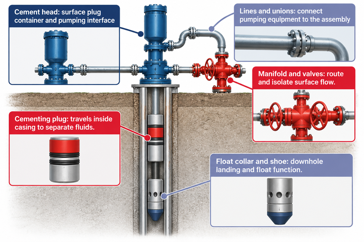
The head contains and releases the plug. The plug provides fluid separation while moving through the casing. The manifold routes flow between pumping lines and the head. Float equipment provides the landing and flow control function down hole. A top drive, swivel, handling assembly, lines, unions, pumps and valves can interact with the job without being the same component.
| Item | Location/role | Evidence owner |
|---|---|---|
| Cement head | Surface plug container and string/pumping interface | Head drawing, manual and test record |
| Cementing plug | Travels inside the casing to separate fluids | Plug specification and compatibility record |
| Manifold/valves | Routes and isolates the surface flow path | Flow schematic and component records |
| Float collar/shoe | Downhole landing and float function | Float-equipment specification |
| High-pressure lines/unions | Connect pumping equipment to the surface assembly | Line, union, inspection and pressure-test records |
The component documentation should identify its interface. FIG 1502 describes a union interface. Likewise, the presence of an API casing or drill-pipe designation on a lower connection doesn’t mean the entire assembly is certified to that specified product. The API Monogram program ties mark use to a licensed organization, facility, applicable specification, and conforming product.
This separation also supports incident review. If there’s a leak from a connection, the investigation would consider mating surfaces, seals, make-up condition, line support, valve alignment, pressure history, and identification of the components. If the plug is not indicated, the question set includes the indicator and release path, but it cannot skip directly to a downhole failure conclusion.
Cement Head Selection Checklist
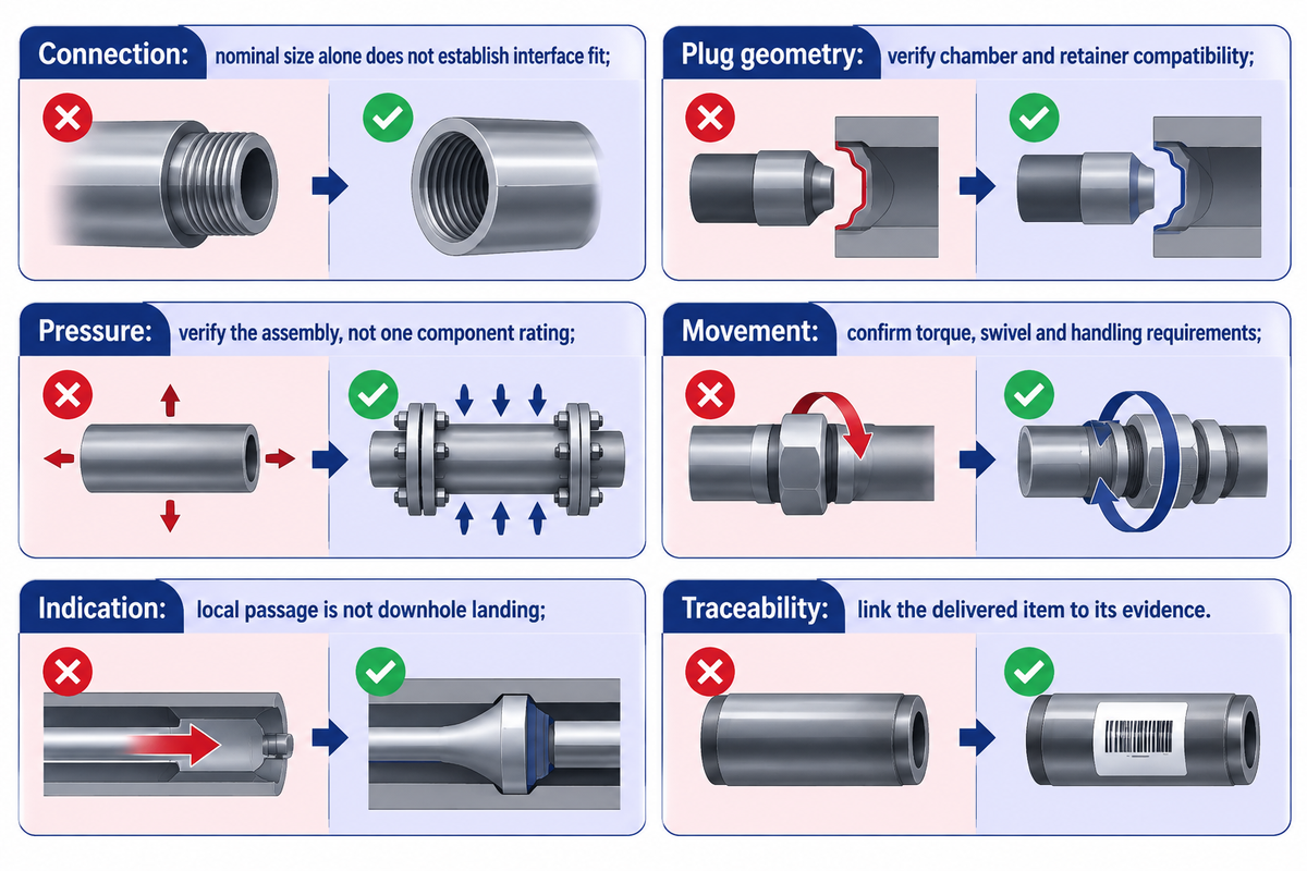
Begin with cementing program, not a product name. The following checklist turns the cementing program into a compatibility and engineering review.
- String interface State casing or drill-pipe size, grade where applicable to the connection, exact thread or approved coupling/clamp drawing, and handling or top-drive interface where applicable. Verify the drawing captures the offered configuration.
- Plug program. List the count and outside diameter and length of plug, chamber position, retainer arrangement, release order, and compatibility evidence. A description of a “double-plug head” without actual plug geometry is inadequate.
- Movement requirement. Is rotation, reciprocation, a full-bore path, or a stationary arrangement required? Link that requirement to the swivel, torque path, handling system, and approved operating plan.
- Control and confirmation. State release method (manual, remote), available energy source, visible indication, communications, and approved confirmation chain. Don’t consider a local indicator as proof of downhole landing.
- Service envelope. List the required working pressure, temperature and fluid/service conditions, and identify the lowest-rated item across the head, valves, lines, unions, adapters, and connected assembly.
For available models, size-specific data, and the information needed for a supplier review, use the cement head configurations and quotation inputs page. The well-program input packet builder can also help organize the inputs before a supplier review. Keep the request tied to the specific drawing and offered assembly, rather than copying a headline rating for another size.
| Input | Evidence requested | Mismatch to prevent |
|---|---|---|
| String and lower connection | Approved connection drawing/gauge record | Nominal size matches but interface does not |
| Plug dimensions and count | Chamber and retainer drawing | Plug is retained, obstructed, or cannot be loaded |
| Pressure/service case | Assembly rating and test record | One component rating is mistaken for the system rating |
| Movement | Torque/swivel/handling evidence | Rotation need is discovered after selection |
| Release and indication | Manual, control logic and indicator states | Local passage is mistaken for landing |
| Identity and traceability | Serial/lot linkage, inspection and certificate scope | A generic certificate is assigned to the delivered item |
Pre-Job Verification and Stop-Work Signals
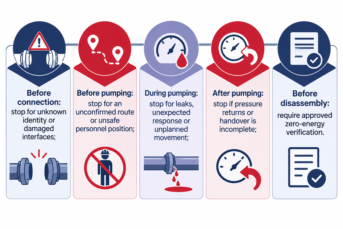
A useful verification plan covers five time windows: before connection, before pumping, during pumping and release, after pumping, and before disassembly. The last one is the easiest to overlook. Pressure can re-accumulate after flow stops, and the string can move while pumping or circulation starts. Neither hazard depends on a plug-release malfunction.
The OSHA oil and gas servicing guidance describes pressure testing of pumps and lines, proper valve alignment, inspection of hammer unions, controlling exposure of personnel, and operators staying at controls. These are safety principles, not alternatives to the well-specific program.
“During the time between the closure of the valve and the removal of the cement bonnet, pressure continued to build up in the system.”
In that case, the calculated buildup was greater than 140 psi, and personnel didn’t recognize that the system was pressurized before the bonnet was removed. The takeaway is regarding state verification and handoff: “pumping stopped” and “the return line was drained” don’t guarantee that all pressure is removed.
| Window | Evidence/observation | Stop-work signal |
|---|---|---|
| Before connection | Identity, condition, matching interfaces, complete retainers/seals | Unknown identity, damaged sealing face, mismatched thread/union, missing part |
| Before pumping | Approved flow path, valve alignment, line support, personnel positions, communications | Unconfirmed route, unsupported line, person in line of fire, unclear command authority |
| During pumping/release | Expected pressure/flow response, leak state, local indication, string movement | Unexpected pressure response, leak, failed indication, unplanned movement, loss of communication |
| After pumping | Pressure state over time, isolation/handover status, thermal effects | Pressure returns, status cannot be independently confirmed, handover is incomplete |
| Before disassembly | Approved zero-energy verification and release authority | Any uncertainty, tight connection suggesting pressure, or change from verified state |
This guide outlines verification and escalation logic; it doesn’t sanction a pressure test, valve sequence, bypass, repair, or disassembly. Those actions remain within the approved procedure, competent-person roles, site controls, and exact equipment manual.
Troubleshooting by Symptom, Without Bypassing Pressure Safety
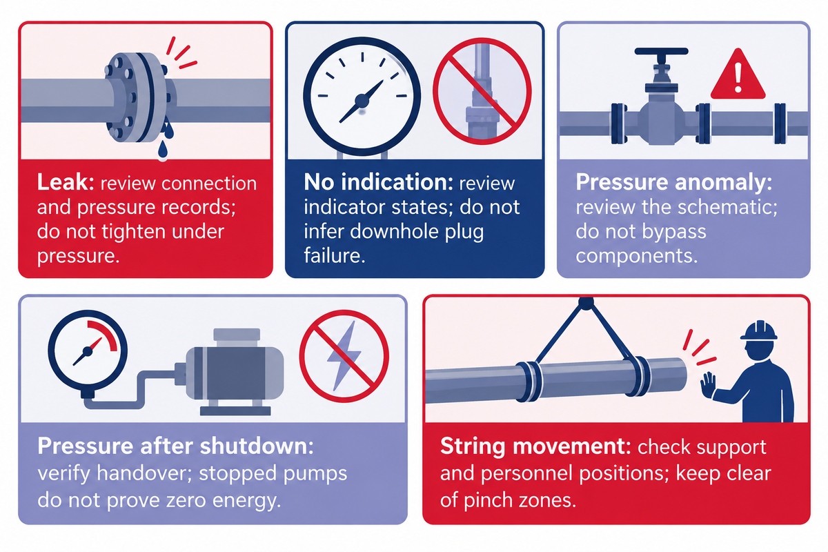
Troubleshooting should progress from observation to one of the cause classes, then to the record or approved check that can differentiate the possible causes. It shouldn’t progress from a symptom directly to the repair. A leak, a failed indicator, a pressure anomaly, and string movement have different evidence paths, but each can create a stop-work condition.
| Observation | Possible cause class | Evidence to check | Do not infer or do |
|---|---|---|---|
| Leak at head/connection | Seal, surface damage, make-up, mismatch, pressure path | Identity, inspection, connection and pressure records | Do not tighten or dismantle until the approved isolation and zero-energy verification are complete |
| Indicator does not change | Indicator condition, plug not passing local point, release-path issue | Indicator states, plug program, approved confirmation chain | Do not declare downhole plug failure from the indicator alone |
| Unexpected pressure response | Flow restriction, valve/path state, line or connection issue, plug event | Time-linked pressure/flow record and approved schematic | Do not bypass a component to “see if flow returns” |
| Pressure after shutdown | Trapped volume, thermal expansion, isolation state | Post-job monitoring and verified handover state | Do not treat stopped pumps as zero-energy proof |
| Casing/string movement | Pump/circulation force, support or handling state | Operating command, personnel positions, elevators/support state | Do not enter the pinch zone or assume movement is a head failure |
IADC Alert 99-24 documents a separate mechanical path: after about 1,600 ft of 8-5/8-inch casing had been run, pump start caused the casing to move upward through the elevators while a worker was positioned near the head, producing a pinch injury. This illustrates why personnel location and expected string movement belong in the verification plan.
When an observation is outside the expected program, the sensible response is to preserve the evidence, time, pressure and flow readings, status of commands and valves, local indications, condition of the equipment, and equipment identity. The responsible team can then evaluate the record versus the approved procedure instead of losing information due to an improvised intervention.
Time-linked pressure trends are especially useful when the question is whether pressure remained stable, returned after shutdown, or changed with an authorized command. They preserve the sequence without inviting personnel to disassemble equipment or attempt reverse flow outside the approved contingency plan.
Cement Head Maintenance, Storage, and Spares
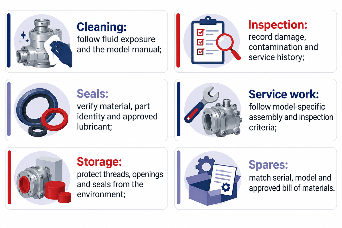
Maintenance should follow the exact design, observed condition, service history, fluid exposure, storage environment, and manufacturer criteria. Ignoring these in favor of a uniform, calendar-based program for all cement heads would mean treating similar items the same way, regardless of the differences in the retainer, indicators, seals, and access points, as well as the material from which they’re made and its duty.
| Lifecycle point | What the record should cover | Decision driver |
|---|---|---|
| Post-job cleaning | Cement residue, accessible passages and external condition | Fluid exposure and manual |
| Inspection | Sealing faces, threads/unions, body, retainers, indicator and valves | Observed damage, contamination and service history |
| Seal management | Correct material, part identity, condition and approved lubricant | Design, fluid and storage condition |
| Functional/service work | Retainer movement, indicator alignment and model-specific assembly | Manual criteria and inspection findings |
| Preservation/storage | Protected threads/openings, corrosion condition and seal storage | Environment and duration |
| Spares readiness | Exact O-rings, gaskets, indicator and retainer parts | Serial/model and approved bill of materials |
Complete spiral retaining-pin servicing follows the applicable model’s maintenance instructions. The condition of the head and its service history will be considered, in conjunction with the instructions for that model. Inspect sealing faces, gaskets, O-rings, retainers, and indicators against the correct drawing, then record replaced parts and the basis for return to service.
Storage is part of reliability. Protect external threads and openings from impact, moisture, and contamination. Seal materials should be stored in the conditions prescribed and traceability between the head, its components and maintenance record should be preserved. Visual inspection can identify damage or contamination, but it doesn’t by itself prove safe pressure service. OSHA’s special-services guidance treats pressure testing, valve alignment, hammer-union inspection, and personnel exposure as controlled safety matters rather than visual-only proof.
Documents, Traceability and Credential Scope
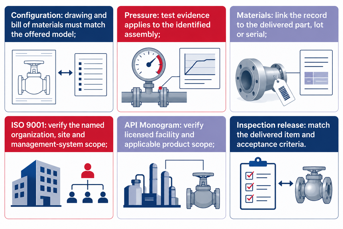
A technical claim is useful only when its evidence names the right owner and scope. The Credential Scope Boundary separates configuration-related evidence from company-related credentials. The associated supplier verification checklist can be used to perform the same ownership checks during an RFQ. This prevents a supplier’s management-system certificate, a thread designation, or a reference to an API specification from being presented as product certification for the delivered cement head.
Material records should identify the steel grade prescribed, and link that record to the pressure containing part. These records should also identify the party responsible for manufacture, as opposed to assuming the supply-chain coordinator did this for all the components.
| Claim | Evidence | Owner that must match | What it does not prove |
|---|---|---|---|
| Configuration and interfaces | Approved drawing and bill of materials | Responsible designer/manufacturer and offered model | Delivered serial identity without linkage |
| Working-pressure evidence | Design basis and test/inspection record | Exact assembly and named test issuer | Every attached line, union, adapter, or field assembly |
| Material/traceability | Material record linked to part/lot/serial | Delivered pressure-containing component | Another component made from the same nominal grade |
| ISO 9001 certification | Current certificate with holder, site and scope | Named organization/site | Automatic certification of each product |
| API Monogram | Current official license/scope plus marked conforming product | Licensed organization and facility | Unlisted products or another supplier’s item |
| Inspection release | Inspection report tied to item/lot and acceptance criteria | Named inspection party and delivered item | Product certification beyond the report’s item and acceptance scope |
API describes its Monogram Program as a voluntary licensing program for products that comply with relevant API specifications. API also states that the mark can be applied only to new conforming product made by the licensed organization at the licensed facility. A reference to API 7-1, which concerns rotary drill-stem elements, cannot be converted into a blanket Monogram claim for an entire cement-head assembly.
ISO explains ISO 9001 as a quality-management-system standard. If certification is claimed, check the actual certificate holder, location, scope, issuer, and validity. A management system audit is a different type of evidence from product drawing, pressure test, material record or current API Monogram scope.
A cement-head API Monogram claim for China Welong requires a current official record showing the licensed organization, facility, applicable product specification, and conforming product. The same ownership discipline applies to ISO 9001: name the certificate holder and management-system scope shown on the current certificate rather than transferring a group-level statement to a delivered item.
Frequently Asked Questions
How does a double-plug cement head work during cementing?
A double plug head holds bottom and top plugs in defined chamber positions. The bottom plug is released ahead of cement slurry and may be launched before or after spacer according to the approved program; the top plug follows the slurry before displacement. Retainers control release at the planned stages. Exact plug design, spacing, and the method of release, as well as downhole landing, diaphragm rupture, float-collar engagement and successful displacement are assessed using the approved job procedure and expected pressure, volume and flow; the exact loading, valve alignment, release method, and confirmation steps remain model- and procedure-specific.
Does a plug-passage indicator prove that the plug reached the float collar?
No. A passage indicator shows that a plug has moved beyond a defined sensing point in the head. It does not prove downhole landing, diaphragm rupture, float-collar engagement, or successful displacement. Treat the indication as one local data point. Confirm next state using the approved job procedure and expected evidence of pressure, volume and flow.
Why is the bottom plug released before the top plug?
The bottom plug separates cement slurry from the fluid ahead, which is usually a spacer, and is designed to open at its landing stage to allow slurry to enter the annulus. The top plug separates slurry from displacement fluid and remains a solid barrier for the final landing/bump event. Exact plug design and job procedure govern the bump job.
What releases a cementing plug from the head?
A retaining or releasing assembly holds the plug and clears its travel path at the planned release stage. There are various methods of actuation (i.e. manual, pneumatic, hydraulic or remote). The correct method, control state, and indication are defined by the exact head and approved procedure.
What does bumping the top plug mean?
The planned surface response is a pump-pressure increase when the top plug reaches its landing position on the lower plug or landing structure, and further displacement can’t continue in the same manner. The expected response and allowable limits belong to the well-specific program. A generic pressure increment shouldn’t be copied to another job and local indication alone doesn’t prove that the complete downhole event has occurred.
What information belongs on the commercial cement head quotation page?
Provide the ID of the document that links the supplied serial/lot to the approved design, plus the casing and plug program, operating boundaries, pressure and service conditions, and evidence requirements listed on the commercial cement head page.
Key takeaway
A cement head is not selected by one type label or headline rating. Integrate the string, plugs, movement, control method, the complete service condition, and evidence pack. Keep local indication separate from downhole proof, and keep company credentials separate from product-specific records.
About China Welong
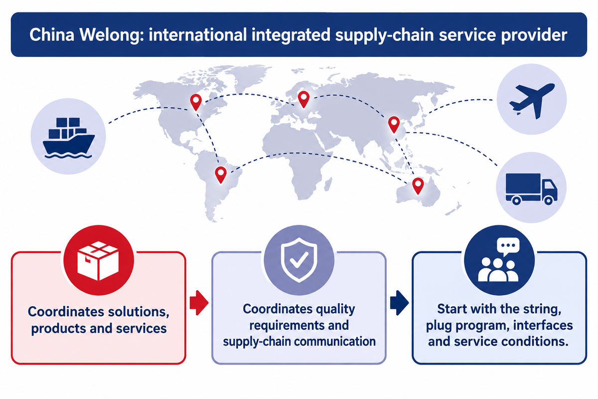
Founded in 2001, China Welong works as an international integrated supply-chain service provider for oilfield and customized products. Its role includes coordinating solutions, products, services, quality requirements, and supply-chain communication for customers across multiple markets. A well-prepared request package helps kick start coordination at the actual string, plug program, interfaces, service conditions and evidence.
Discuss a cement head requirement
Technical note: This article provides guidance for equipment-selection and equipment-verification. Field execution, pressure work, isolation, testing, repair, and disassembly remain subject to the governing requirements, approved well program, competent-person roles, site controls, and exact equipment instructions. OSHA’s special-services guidance likewise places pressure tests, valve alignment, line and union condition, and personnel exposure under controlled procedures.
Related Articles
- Cementing tools full-string guide
- Upstream wellhead and well-control stack guide
- Blowout preventer guide
- Casing, tubing, and drill-pipe handling-interface guide
References & Sources
- SLB Energy Glossary: Cement head definition.
- Occupational Safety and Health Administration: Oil and gas servicing – special services.
- International Association of Drilling Contractors: Alert 10-34 – offline cementing pressure incident.
- International Association of Drilling Contractors: Alert 99-24 – casing movement incident.
- American Petroleum Institute: API Monogram and APIQR program.
- International Organization for Standardization: ISO 9001 explained.
- Drilling Contractor: Remote five-plug cementing operation, August 2025.
Why Buyers Work With Welong
About Welong Engineering Support
China Welong supports oilfield buyers with engineered supply-chain service for drilling tools, well-control equipment, rig-floor tools, casting parts, and industrial forged components.
Project Review Before RFQ
We help buyers compare tool family, material route, API or ISO requirements, inspection records, supplier capability, delivery risk, and documentation needs before a purchase decision is finalized.
Request An Oilfield QuoteCompany Profile // Data Sheet
CompanyChina Welong International Supply Chain
BrandWelong
CountryChina
Business TypeOilfield tools and industrial supply-chain partner
Main ProductsDownhole drilling tools, fishing and milling tools, wellhead and well-control equipment, oilfield hoses, rig-floor handling tools, mill rolls, and forgings
Engineering CapabilityTool-family selection, specification envelope review, API / ISO reference support, material traceability, inspection coordination, and supplier-route comparison
RFQ Data NeededTool type, size, connection, rating, grade, standard, quantity, drawings, and delivery target
Websitewelongoiltools.com