Get in touch with Welong Company

Engineering guide · Informational support content
Downhole drilling tools are below-surface components that transmit load and fluid through the drill string, control trajectory, deliver hydraulic power, sense conditions, enlarge the bore, or recover the drilling system. A productive assembly selection process begins not with the product, but with the job and the complete assembly.
Bottom line: select a tool family only after five inputs are verified: objective, environment, load or energy path, assembly compatibility, and acceptance evidence. If one critical input is unknown, the defensible result is do not shortlist yet. A surface signal, catalog label, or previous run is not enough by itself.
Article boundaryDrilling string and BHA
Original atlas11 function groups
Selection method5 verified gates
Failure method4 signal groups
What Are Downhole Drilling Tools? Scope and System Boundaries
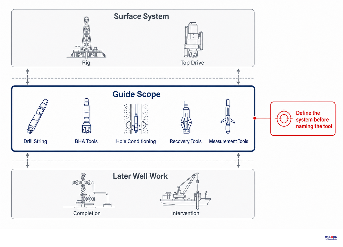
In this guide, a downhole drilling tool is any component deployed down-hole to be part of, or directly serve, the drilling string and BHA. This category includes tools that drill, transmit force and fluid, add weight, stabilize, steer, rotate, enlarge the bore, sense, disconnect, recover, or protect the active drilling string.
An OSHA-hosted Petex glossary describes a drill string as the drill-pipe column that transmits fluid and rotational power to the collars and bit. It places a downhole motor directly above the bit and distinguishes the broader drill stem, which can include collars, stabilizers, and specialty items. That vocabulary gives us a system boundary; it doesn’t create an exhaustive product taxonomy.
| Term | How it is conveyed | Job stage | Typical position | Main objective | In this guide? |
|---|---|---|---|---|---|
| Drill-string / BHA tool | Made up in the string | Drilling | Surface to bit, especially lower BHA | Transmit, steer, rotate, measure, or protect | Yes |
| Down-the-hole hammer | Drill string with pneumatic or fluid energy | Rock drilling / water well / mining contexts | Immediately above bit | Percussive rock breakage | Only to prevent term confusion |
| Wireline tool | Electric line or slickline | Logging or intervention | Deployed through the well | Measure, set, retrieve, or service | Boundary only |
| Completion tool | Tubing, work string, or intervention conveyance | Completion / production | Production interval or completion string | Control flow and production | Boundary only |
| Coiled-tubing tool | Continuous tubing | Intervention or drilling | End of coiled tubing | Cleanout, stimulation, milling, or drilling | Only when it acts in a drilling job |
| Surface drilling equipment | Rig-mounted | Drilling | Above wellhead | Rotate, hoist, pump, and control | No |
DTH is not a harmless abbreviation. Someone searching for a down-the-hole hammer may mean a percussive rock-drilling system, while a drilling engineer may mean the full set of downhole components. Confirm the drilling method and well context before comparing products.
The boundary also matters when comparing categories of downhole tools. Casing, packers, bridge plugs, and perforating guns are normally completion technologies. Logging tools may run on wireline, while coiled tubing and wireline support intervention or workover. Fishing tools and mills enter this guide only when their job is recovery or access during drilling operations. That distinction prevents a broad oil and gas industry equipment catalog from being treated as one interchangeable tool set.
Where Each Tool Sits in the Wellbore: Drill String and BHA Interaction Map
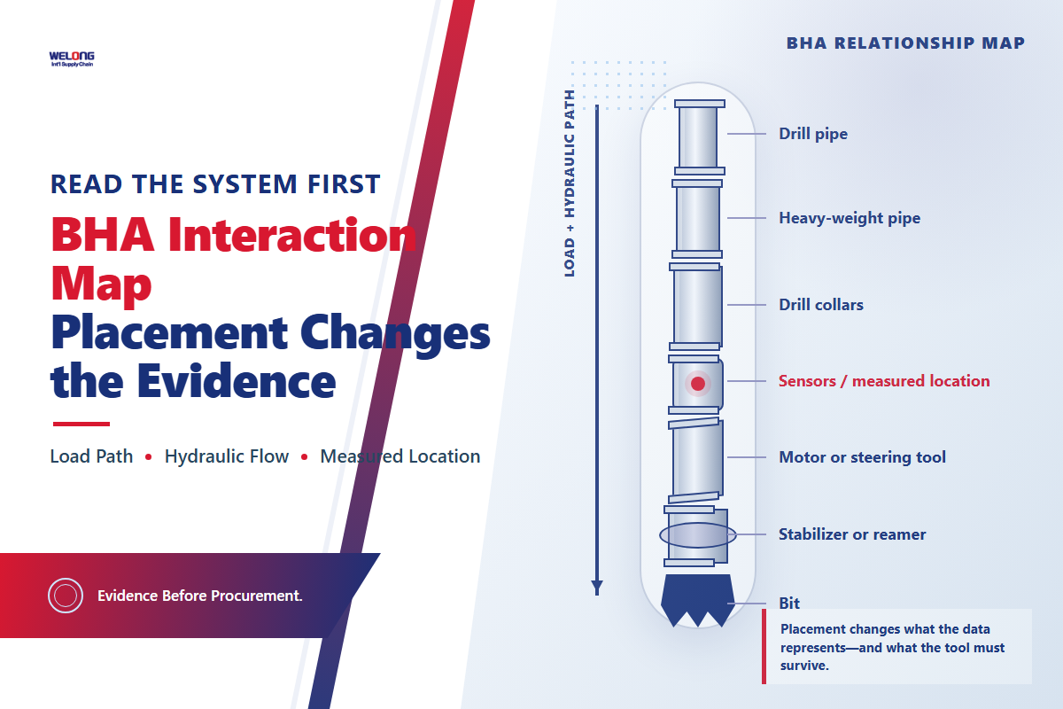
Even the best individual tool can’t compensate for a poorly selected assembly. Its location determines which axial loads, torque, rotation, fluid flow, and data paths pass through or depend on it. Selection therefore begins with the drill string and BHA position where the required function must act.
Placement effects are measurable. One 2025 Scientific Reports reamer study modeled the complete string from top drive to bit and examined coupled axial, torsional, and lateral vibration. Its case BHA placed a reamer 6.9 m from the bit at roughly 3,993 m depth. Changing WOB, RPM, stabilizer OD, and stiffness changed the response. Those values describe one modeled and field-checked system; they’re evidence that the interactions matter, not a reusable operating recipe.
Measured location matters too. One 2024 World Oil technical article explains that surface WOB can poorly represent downhole WOB in long extended-reach wells. It also warns that shock-and-vibration channels differ with sensor specification, mounting, and processing. “The reading changed” is incomplete unless the channel, sensor, location, and operating state are known.
| Path | Primary inputs | Components that strongly influence it | Evidence to request | Unsafe shortcut |
|---|---|---|---|---|
| Axial load | Hookload, WOB, buoyancy, contact | Pipe, HWDP, collars, bit, jars | Placement, dimensions, WOB source, load history | Surface WOB equals bit WOB |
| Torsion | Surface RPM, torque, bit-rock interaction | Connections, string, motor, bit, reamer | Torque limits, make-up records, downhole RPM where available | Constant surface speed means constant downhole speed |
| Bending / trajectory | Inclination, dogleg, side force, stiffness | Collars, stabilizers, bent housing, RSS, reamer | Trajectory, spacing, OD, stiffness transition | Directional optimum is also vibration optimum |
| Hydraulic | Flow, density, rheology, pressure | Motor, bit nozzles, MWD, restriction, reamer | Flow window, pressure-drop model, fluid limits | Rated flow proves assembly compatibility |
| Magnetic | Sensor spacing and magnetic interference | Nonmagnetic collars, MWD, nearby steel | Spacing drawing, material certificate, OEM rule | “Nonmag” label proves the full layout |
| Telemetry / data | Sensor, sampling, power, transmission | MWD/LWD, wired pipe, surface acquisition | Channel definition, units, time sync, dropout behavior | More channels automatically improve diagnosis |
After the string and BHA have been defined by function, use the drill pipe guide for more detail on that component family.
11 Categories of Downhole Tools: Drill Bit, BHA, Casing, Completion, and Intervention Roles
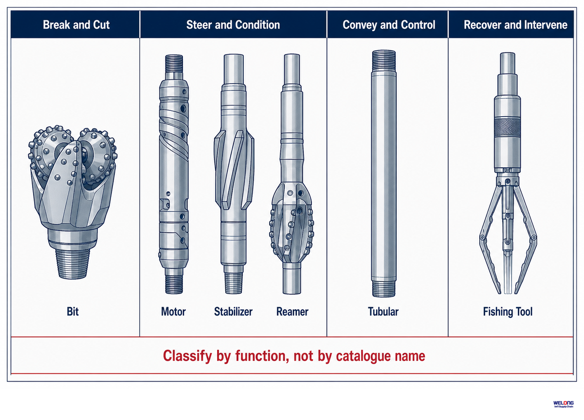
The 11-Function Downhole Tool Atlas is organized by the function each family provides within the drilling string. It is a China Welong editorial synthesis based on public technical descriptions and system-level evidence. The directory isn’t a formal API classification, nor does it imply that any given family is appropriate for any given BHA.
That distinction matters. API’s official Spec 7-1 webstore page says the standard covers defined rotary drill-stem elements, including kelly valves, kellys, subs, steel and nonmagnetic drill collars, HWDP, bit connections, and stabilizers. It excludes drill pipe, tool joints, connection design, gauging practice, and performance properties. Motors, jars, measurement tools, and the rest of this atlas must not be pulled under that title by assumption.
| No. / function | Common families | Typical system position | Input → output | Key limit to verify | Failure or mismatch clue |
|---|---|---|---|---|---|
| 1. Cut | Roller-cone, PDC, coring bit | Bottom of BHA | WOB + rotation + fluid → rock removal | Formation, hydraulics, connection, operating window | Cutter damage, dull pattern, unstable torque |
| 2. Transmit | Drill pipe, subs, connections | String length | Surface rotation, load, fluid → BHA | Connection, OD/ID, torque, fatigue exposure | Washout, connection damage, twistoff indication |
| 3. Weight / stiffen | Drill collars, HWDP | Lower string / BHA transition | Mass and stiffness → WOB and stability | Bending, neutral point, magnetic requirement | Fatigue, contact wear, unstable load transfer |
| 4. Stabilize | String and near-bit stabilizers | Selected BHA stations | Wall contact → radial support and tendency | OD, gauge, spacing, trajectory objective | Gauge loss, wear, unexpected directional tendency |
| 5. Steer | Bent motor housing, RSS, deflection tools | Near bit | Command / bend / pads → trajectory change | Dogleg target, BHA tendency, telemetry | Toolface control or trajectory response differs from plan |
| 6. Convert energy | Positive-displacement motor, turbine | Above bit or steering section | Hydraulic energy → downhole rotation | Flow, pressure drop, temperature, elastomer or bearing limits | Differential pressure, speed, or output changes |
| 7. Measure / communicate | MWD, LWD, shock/vibration sensors | Instrumented collars | Downhole state → telemetry and recorded data | Sensor range, sampling, power, bandwidth, magnetic spacing | Dropout, drift, saturation, inconsistent channels |
| 8. Enlarge / condition hole | Reamer, underreamer, hole opener | Near bit or selected BHA position | Rotation + load → larger or conditioned bore | Activation, gauge, cutting load, BHA dynamics | Vibration rise, gauge loss, activation uncertainty |
| 9. Release / impact | Drilling jar, accelerator | Placed for free-point and load path | Stored energy → axial impact | Jar direction, load, delay, placement, temperature | Unexpected firing, no release, damaged connection |
| 10. Recover | Overshot, spear, magnet, mill | Bottom of recovery assembly | Engagement or cutting → retrieval / access | Fish geometry, access, circulation, tensile path | Cannot engage, reduced circulation, additional debris |
| 11. Protect / isolate | Shock sub, filter, float, crossover, protector | Where the hazard or interface occurs | Shock, debris, backflow, interface → controlled condition | Pressure, flow, connection, service procedure | Restriction, leakage, excessive shock transmission |
Within this guide, a drill bit and the bottom hole assembly (BHA) belong to the drilling system; completion tools prepare or control later well functions; intervention tools change or recover an existing condition. A mill can appear in more than one lifecycle, so its placement follows the job objective rather than the product label alone.
Refer to the drill collar function and selection guide and drilling mud motor guide for family level questions and avoid applying model numbers directly from this atlas.
5-Gate Downhole Tool Selector for Oil and Gas Industry Operational Optimization
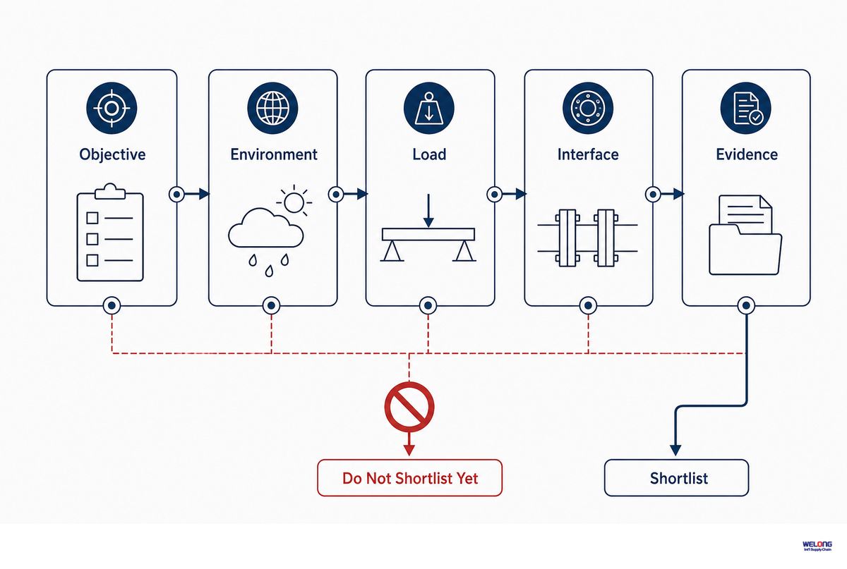
The 5-Gate Condition-to-Tool Selector tests each candidate against five sets of criteria in sequence. If a tool fails any gate, it leaves the shortlist. An unidentified key metric should put the decision on hold. This rule is stricter than “used before” for a reason: the same tool may encounter different formation, temperature, flow, trajectory, connection, or evidence requirements on another project.
The aim is not to improve one component in isolation. System-level drilling improvement must cover the bit, BHA, drill string, hydraulics, target zone, rig interfaces, and acceptance evidence without moving risk into another part of the system.
Selection rule: if the objective, operating envelope, interface, or acceptance evidence is unknown, the tool family may be plausible, but model selection is premature.
1 · ObjectiveWhat must change downhole?
2 · EnvironmentWhat will the tool be exposed to?
3 · Load / energyHow is work delivered and reacted?
4 · CompatibilityDoes it fit the whole assembly?
5 · EvidenceWhat proves identity and acceptance?
| Input to verify | Question | What it can change | Evidence | Stop outcome |
|---|---|---|---|---|
| Job objective | Cut, steer, rotate, enlarge, measure, release, or recover? | Entire function family | Drilling program and failure/recovery objective | No objective → no shortlist |
| Formation / hazard | Strength, abrasiveness, interbedding, loss, instability? | Cutting structure, aggressiveness, control method | Offset data and current geological basis | Unknown hazard → qualify assumptions |
| Hole geometry | Hole size, inclination, dogleg, underreaming requirement? | OD, placement, stiffness, trajectory capability | Well plan and dimensional drawing | Interference risk → reject |
| Temperature | Expected, transient, and contingency temperature? | Elastomer, electronics, seals, lubricant, metallurgy | Rated envelope and well basis | No margin check → pause |
| Pressure | Hydrostatic, differential, internal, external, test? | Housing, seal, motor, valve, activation | Pressure model and tool rating | Rating not comparable → reject |
| Fluid / flow | Rate, density, solids, rheology, chemistry? | Motor speed, pressure loss, cooling, erosion, telemetry | Hydraulics model and OEM fluid limits | No common window → reject |
| WOB / torque / RPM | Surface or downhole? Steady or transient? | Cutting, fatigue, connection, vibration, motor output | Channel definition, operating plan, connection limit | Location unknown → no threshold |
| Vibration / shock | Axial, lateral, torsional, HFTO; which sensor? | Electronics, seals, fatigue, bit and BHA design | Sensor range, sampling and position | Inference from surface data only → escalate |
| Mechanical interface | Connection, OD, ID, length, fishneck, make-up? | Fit, pressure loss, load path, serviceability | Controlled drawing and connection procedure | Mismatch → reject |
| Directional / magnetic interface | Stabilizer tendency, bend, sensor spacing, interference? | Trajectory response and measurement quality | BHA model, spacing rule, material certificate | Conflicting requirements → redesign |
| Data / service interface | Protocol, ownership, time sync, dropout, downlink? | Automation, diagnosis, remote support | Interface control document and failure response | No fallback → do not automate |
| Acceptance evidence | Which records prove identity, condition, test, and release? | Run / reuse / repair / reject decision | Traceability, inspection, repair, test, concession record | Evidence gap → quote condition |
One 2025 deep-well field study illustrates why the envelope check is separate from the tool name. Its specific system was laboratory-tested at 61.4 MPa and 120.8°C, then operated around 59.2 MPa and 115°C in the reported field trial. The reusable lesson is rating-versus-actual comparison across multiple parameters. Copying those values to another design would be a category error.
Worked example, not a recommendation: suppose a deviated interval needs hydraulic bit rotation and real-time trajectory data. “Mud motor” passes the objective gate. It still cannot enter a model shortlist until formation, temperature, pressure, flow, expected differential pressure, connection, OD, bend/trajectory demand, magnetic spacing, MWD interface, and evidence package are verified. If the flow windows of the motor and MWD do not intersect, both products can be individually valid and collectively wrong.
The fictional input card below shows the level of detail a selector needs. It’s a data-structure example, not a design basis, operating window, or acceptance criterion. Replace every value with controlled well, BHA, fluid, and supplier data before comparing models.
| Input field | Illustrative value | Selection question it opens | Evidence owner |
|---|---|---|---|
| Planned measured depth | 4,600 m | What run exposure and retrieval plan apply? | Well program |
| True vertical depth | 3,850 m | Which pressure and temperature model is controlled? | Drilling engineering |
| Maximum inclination | 92° | How do gravity, contact, and cuttings transport change? | Directional plan |
| Planned dogleg | 3° per 30 m | Can the assembly meet trajectory and bending limits together? | Directional engineering |
| Open-hole diameter | 216 mm | What gauge, clearance, and flow-area checks are required? | Hole-section program |
| Minimum drift diameter | 178 mm | Can every component pass the verified restriction? | Well construction record |
| Candidate maximum OD | 171 mm | Is the clearance acceptable under expected wellbore conditions? | Supplier drawing |
| Static temperature | 155°C | Which electronics, seals, lubricant, and elastomer ratings govern? | Temperature model |
| Circulating temperature | 132°C | Which state controls each component rating? | Hydraulics model |
| Hydrostatic pressure | 82 MPa | Does the complete pressure envelope remain within rating? | Well and fluid model |
| Available tool differential | 6.5 MPa | Do motor, MWD, bit, and surface constraints intersect? | Hydraulics model |
| Planned circulation | 2,100 L/min | Are tool, telemetry, cleaning, and erosion windows compatible? | Drilling program |
| Illustrative motor differential | 4.2 MPa | Does the candidate remain inside its verified operating map? | Supplier performance data |
| Fluid density | 1,350 kg/m³ | Which pressure loss and buoyancy assumptions change? | Fluids program |
| Solids concentration | Approximate example: 3% | What wear, plugging, and inspection risks need review? | Fluids report |
| Illustrative surface rotation | 60 rpm | What combined bit speed and torsional response should be checked? | Operating roadmap |
| Planned bit speed | 180 rpm | How do motor output, surface rotation, bit, and vibration limits interact? | Operating roadmap |
| Required sensor bandwidth | 100 Hz | Can the channel detect the dysfunction being monitored? | Measurement specification |
| Telemetry response allowance | 8 s | Is the delay safe for advisory or active control? | Interface control document |
| Planned run exposure | 120 hours | What maintenance, inspection, and tool-life evidence is required? | Run plan and service history |
| Illustrative pressure hold | 95 MPa for 15 min | Which approved test procedure actually governs release? | OEM or authorized test procedure |
| Dimensional review trigger | 0.25 mm | Is this value permitted by the applicable drawing and procedure? | Controlled acceptance document |
Use the site’s tool-family selector only after the five gates have a recorded answer.
A horizontal well, offshore section, corrosive fluid, or unconventional formation can change the governing wellbore conditions. Selection inputs should therefore include formation properties, expected tool life, durability evidence, whether the assembly must be retrievable, and the operational consequence of downtime. Those fields protect well performance and productivity without turning a catalog claim into a guaranteed outcome.
4-Signal Failure Triage Loop for Directional Drilling Tools
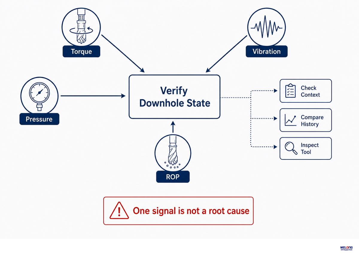
Failure triage starts with four signal groups: torque/vibration, pressure/flow, ROP/trajectory response, and physical or recovered-tool condition. One group can narrow the next check; it seldom identifies a single failed component.
One 2023 HFTO review places high-frequency torsional oscillation mainly in the lower BHA and lower drill string and explains why it can be attenuated before reaching surface. Its 2024 SPE counterpart reports HFTO around 20–200 Hz in an overview and notes that off-axis acceleration or torque sensing may be needed. Quiet surface channels don’t prove a quiet BHA.
That same SPE article describes a real design tradeoff: stabilizer locations needed for directional tendency aren’t always optimal for shock and vibration. That’s why triage must test system interaction before blaming the nearest tool.
| Observed change | Plausible mechanisms | Next evidence check | Do not infer | Escalation boundary |
|---|---|---|---|---|
| Surface torque oscillation | Stick/slip, bit-rock interaction, contact, connection issue | Downhole RPM, WOB, trajectory, bit/BHA state | “The motor failed” | Connection or fatigue limit approached |
| Downhole high-frequency torsion | Bit/BHA/formation interaction | Sensor bandwidth, location, bit and lower-BHA data | Surface trace must show it | Electronics or structural exposure exceeds procedure |
| Lateral shock rises | Whirl, wall contact, stiffness/spacing, hole condition | Downhole accelerometer, trajectory, stabilizer/reamer condition | One universal g-limit applies | Tool-specific rating or safe practice exceeded |
| Standpipe pressure rises | Restriction, plugging, nozzle change, motor loading, fluid change | Flow, fluid properties, circulation response, differential pressure | Pressure rise names the failed part | Pressure envelope or well-control concern |
| Pressure falls | Washout, leak, loss, pump or sensor issue | Independent pressure checks and flow balance | Downhole washout is proven | Loss of barrier or circulation integrity |
| ROP falls | Formation, bit condition, cleaning, WOB transfer, vibration | Lithology, downhole WOB, torque, cuttings, dull evidence | Bit wear is the only cause | Operating change fails or dysfunction rises |
| Trajectory response changes | BHA tendency, stabilizer wear, toolface, formation, sensor quality | Survey quality, toolface, spacing and physical condition | Steering actuator alone is at fault | Survey confidence or dogleg control lost |
| Telemetry drops out | Power, pulser/downlink, shock damage, flow state, data interface | Rig state, power, pressure signature, recorded memory, protocol log | All other downhole tools stopped | No safe operating fallback |
| Recovered wear or crack indication | Contact, fatigue, overload, corrosion, handling | Location, dimensions, NDT method, history, fracture review | Visual severity equals remaining life | Acceptance criterion not met |
| Signals disagree | Different locations, time bases, sensor drift, saturation, real dynamics | Units, calibration, time sync, independent channel | The preferred channel is automatically right | Critical decision lacks corroboration |
Use this loop: record the operating state, compare all four groups, check the most discriminating evidence, then decide whether to continue, adjust, inspect, pull, or escalate. For jar-specific context, see the drilling jar operating guide.
Manufacture or Rental? Inspection Evidence for Stabilizer, Reamer, and Tubular Tools
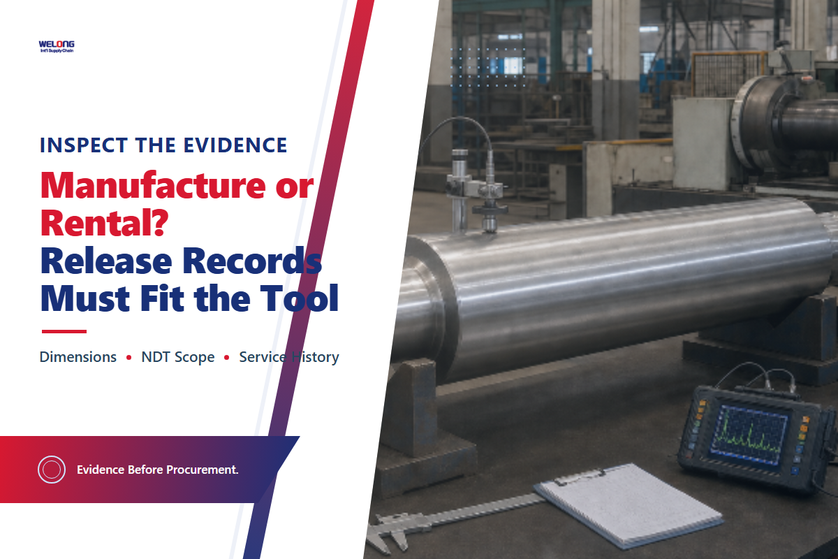
There’s no universal lifespan for a downhole drilling tool. Motors with elastomer and bearing limits, steel drill collars, electronic MWD collars, jars, and cutting structures don’t age through the same mechanism or carry the same acceptance evidence.
Bureau Veritas’ DS-1 overview makes this visible by separating used tubular inspection, specialty-tool maintenance and qualification, and bit/reamer cutting-structure inspection into different volumes. Its page identifies the fifth edition as August 2020. Treat that date as source context, then verify the edition and acceptance basis written into the actual contract.
The official ISO drilling-equipment catalog groups ISO 10424-1 for rotary drill-stem elements, ISO 10424-2 for threading and gauging rotary-shouldered connections, and ISO 10407-2 for inspection and classification of used drill-stem elements. The catalog also marks the cited editions as withdrawn. Edition control therefore belongs in the evidence package: record the contract’s adopted API or ISO document, revision, connection-owner requirements, and any OEM supplement instead of writing “meets ISO” as an undated blanket claim. ISO scope does not replace the drawing, service history, inspection procedure, or authorized disposition.
IADC’s 2026 Bit and BHA Dull Grading Manual announcement calls the resource a recommended-practice framework for drilling forensics, bit and BHA dull grading, failure reporting, and data management. Condition grading helps describe what came out of the hole. It isn’t, by itself, a universal retirement criterion.
| Evidence | Decision it can support | What it cannot prove alone | Owner / source | Currency check |
|---|---|---|---|---|
| Identity and traceability | Correct item, material, serial, revision | Current condition or fitness | Manufacturer / supplier / controlled record | Match physical markings and documents |
| Dimensional inspection | Wear, gauge, wall, interface condition | Absence of hidden cracking | Qualified inspection process | Applicable limits and calibrated equipment |
| Thread and connection inspection | Make-up interface condition | Whole-tool remaining life | Applicable procedure / connection owner | Edition, gauge, calibration, acceptance class |
| Visual / NDT result | Indications detectable by the selected method | Defects outside method sensitivity or coverage | Qualified personnel and procedure | Method, coverage, sensitivity, disposition |
| Pressure or function test | Performance under stated test conditions | Every downhole load combination | OEM or approved test procedure | Medium, pressure, temperature, duration, result |
| Service and run history | Exposure and maintenance context | Condition when records are incomplete | Operator / service provider | Runs, hours, environment, abnormal events |
| Repair / remanufacture record | Work scope, parts, concessions, retest | Unrecorded damage or future performance | Approved repair source | Procedure revision and release authority |
| Dull / damage grading | Consistent condition description and learning | Universal reuse or retirement approval | IADC/operator/OEM framework | Manual version and operator criterion |
| Engineering disposition | Run, reuse, repair, downgrade, or retire | Decision beyond its stated scope | Authorized technical owner | Inputs, assumptions, limits, signature |
Specialty-tool gap: public, tool-specific retirement criteria are less complete for motors, jars, and some reamers than for common drill-stem elements and bit grading. When a public rule is not verified, request the applicable OEM manual, operator procedure, inspection scope, repair history, test result, and authorized disposition. Do not stretch API Spec 7-1 beyond its stated scope.
A rental label, “field-proven” claim, or specialized equipment category doesn’t establish present condition. The evidence package still needs to show what the item was built to withstand, what service it has seen, which inspection method was applied, and who has authority to release it.
Use the site’s evidence package builder to organize those records without pretending that one document proves everything.
Downhole Technologies: Reliability Evidence Before Automation Claims
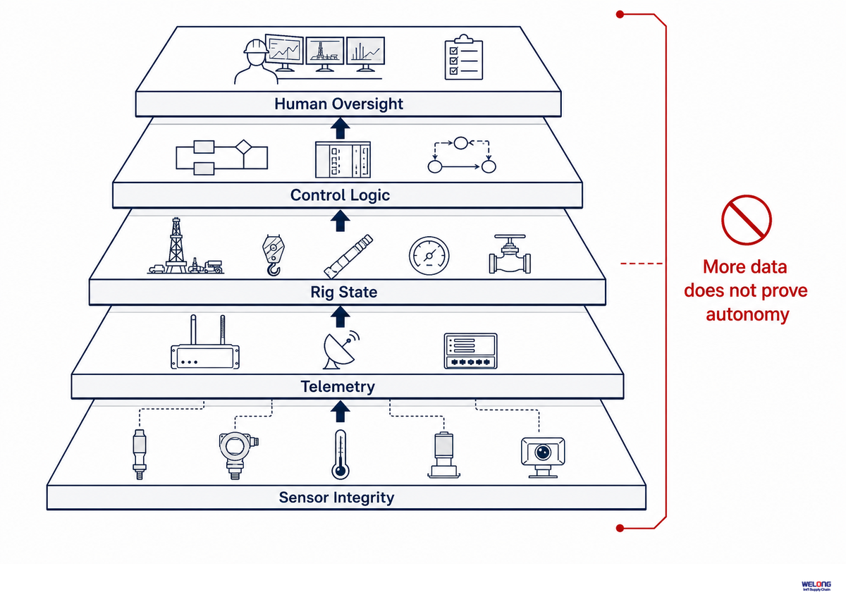
As downhole sensing and automation move from advisory input toward active control, the buyer’s work does not disappear. It shifts to sensor selection, rig-state identification, telemetry error handling, system integration, validation, and clearly defined human override paths.
A 2025 JPT review of automation papers describes a two-well case that reported 85% autonomy and case-specific ROP gains of 25% against an advisory mode and 48% against an average manual baseline. That article says the system needed accurate rig-state awareness through sensor fusion and stronger resilience to unexpected MWD telemetry or downlink disruption. Those percentages belong to that reported comparison; they aren’t a purchasing guarantee.
A second 2025 JPT Fénix case study describes a staged move from advisory to active automation, backed by real-time anomaly detection, digital-twin inputs, dashboards, and communication among the teams. Its operating lesson is staged verification with visibility, not “remove the driller.”
The same 2025 field study cited in the environment gate reported laboratory qualification at 61.4 MPa and 120.8 °C, followed by field operation around 59.2 MPa and 115 °C. Repeating the figures here serves a different check: a quote should separate the rated limit, laboratory verification, actual exposure, and safety margin. They remain boundary conditions from one reported system, not transferable ratings.
Automation may accelerate a response only when the system can identify state changes, preserve context in real time, and fall back safely. A sustainable performance claim also needs a declared boundary, baseline, and measurement period; the presence of downhole sensors is not enough.
| Technology driver | Buyer implication | Evidence requirement | Failure question |
|---|---|---|---|
| More downhole sensors | More channel definitions and compatibility checks | Range, sampling, location, calibration, units | What happens on drift or saturation? |
| Sensor fusion | Rig-state model becomes load-bearing | Input list, validation cases, confidence logic | Can one bad channel dominate the result? |
| Automated parameter changes | Limits and competing objectives need governance | Boundaries, vetoes, audit trail, manual control | How does the system avoid overreaction? |
| Remote operations | Human visibility and responsibility must be explicit | Dashboard, alarm routing, authority matrix | Who decides when communications fail? |
| Multi-vendor services | Interoperability becomes a selection input | Protocol, time sync, ownership, version control | Is the interface tested or merely claimed? |
A defensible outlook is that narrowly scoped automation is progressing, while public case evidence remains specific to the rig, well, tools, data, service interfaces, and operating model. Reliability evidence remains the first priority.
Advanced drilling controls can pursue precision, faster response, or increased safety, but each claim needs a defined baseline and a safe fallback. The objective is to minimize avoidable uncertainty, not to imply that more automation automatically improves every well.
Build the Downhole Solutions Evidence Handoff Before the RFQ
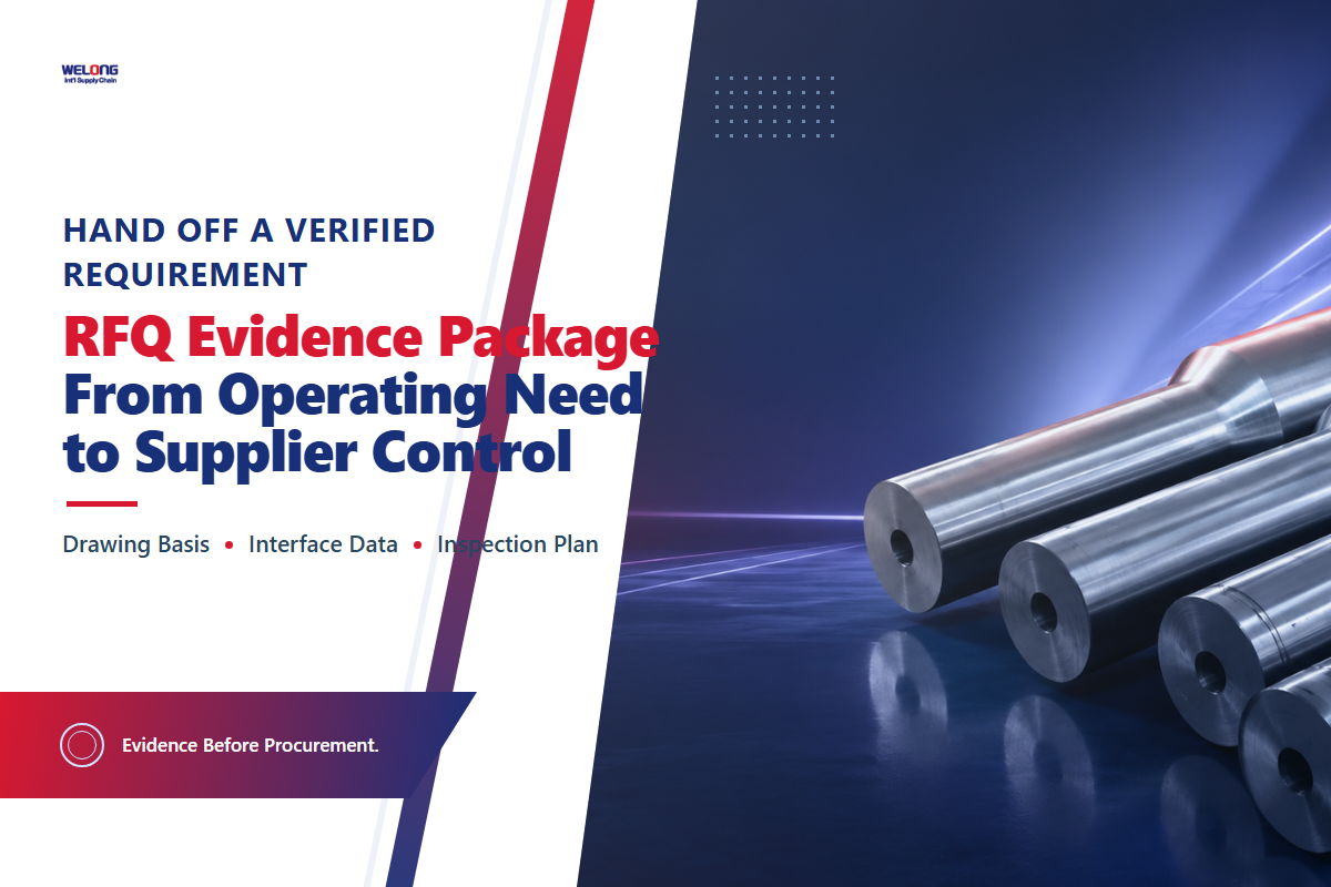
A quote has meaning only when engineering, procurement, QA, and the supplier are pricing the same defined requirement. The handoff should contain independently checked facts, controlled assumptions, visible ambiguities, and acceptance evidence rather than only a product name and delivery date.
- Job objective and success boundary
- Hole section, size, trajectory, and planned BHA
- Formation and known dysfunction risks
- Temperature and pressure basis, including contingencies
- Fluid, flow, solids, and hydraulic window
- WOB, torque, RPM, shock, and measurement location
- Connections, OD/ID, length, and placement constraints
- Directional, magnetic, telemetry, and data interfaces
- Required traceability, inspection, tests, and standards
- Repair history and allowed concessions for used equipment
- Unresolved inputs listed as quote conditions
- Technical approval and change-control owner
China Welong was founded in 2001 and works as an international integrated supply-chain service provider for customized industrial metal products. Its stated service scope includes supplier development and management, purchasing supervision, and quality control, including work connected with oil drilling. That commercial role begins after the technical requirement is defined; it doesn’t replace the five engineering gates.
When the handoff is complete, move to the existing downhole drilling tools sourcing and quality-control solution. That Page owns supplier capability, service scope, and quotation intent. This guide owns the engineering questions that should be answered first.
Turn Open Evidence Gaps Into a Verifiable RFQ
Bring the well conditions, assembly interfaces, and available acceptance records, not only a product name.
Frequently Asked Questions
Q: What do downhole tools mean for a well?
Downhole tools are below-surface components used to drill, measure, steer, enlarge, protect, release, recover, complete, or intervene in a well. They operate where surface access is unavailable, and each unit must fit the planned BHA, well objective, and operating window.
Downhole tools are below-surface components used to drill, measure, steer, enlarge, protect, release, recover, complete, or intervene in a well. This article uses a narrower drilling-system definition: components in or directly supporting the drill string and BHA. Completion, wireline, and coiled-tubing tools are adjacent categories unless they perform the drilling job being discussed.
Q: Why is so much effort put into designing, deploying, and maintaining downhole solutions?
Downhole solutions work where inspection and intervention are difficult, under combined mechanical, hydraulic, thermal, and data constraints, so one mismatch can interrupt drilling, damage adjacent components, or force an unplanned trip.
Downhole solutions work where inspection and intervention are difficult. They can see combined pressure, temperature, fluid, load, shock, vibration, contact, and data constraints. A 2025 field study of multi-parameter downhole risk evaluation illustrates why those conditions must be checked together. One failure may force a trip, interrupt telemetry, damage other BHA components, or change the well plan. Design, deployment, monitoring, inspection, and maintenance address different parts of that risk.
Q: What are the main drilling stabilizer types?
Stabilizer families commonly include near-bit and string positions, with integral- or replaceable-blade constructions. The correct choice depends on BHA position, gauge, blade geometry, directional tendency, formation contact, and repair limits.
Common groupings include near-bit and string stabilizers, plus integral- and replaceable-blade constructions. Selection depends on more than the label. Check gauge or undergauge OD, blade geometry, placement, formation contact, BHA directional tendency, vibration response, repair limits, and the applicable manufacturing and inspection evidence. Then verify how each choice changes build, service, and replacement limits.
Q: How are drill collars and drill pipe different?
Drill pipe transmits rotation and fluid; drill collars add concentrated weight and stiffness near the bit, so they occupy different load-carrying roles and require different dimensional, connection, fatigue, and inspection evidence.
Drill pipe primarily transmits rotation and drilling fluid along the string. Drill collars are thicker-walled, heavier BHA members used to add weight and stiffness near the bit. Material, dimensions, connections, magnetic requirements, fatigue exposure, and inspection class still have to be verified.
Q: What is the future of downhole tools?
Downhole-tool development is moving toward more sensing, integrated models, remote oversight, and staged automation, but adoption still depends on telemetry resilience, interface control, validation, cybersecurity, safe fallback, and human decision authority.
Current direction favors more downhole sensing, anomaly detection, integrated models, remote oversight, and staged automation. Less visible work is equally important: sensor compatibility, time synchronization, telemetry resilience, multi-vendor interfaces, validation, cybersecurity, safe fallback, and human authority. Case studies can show what worked in one deployment; they don’t erase those conditions or prove a universal performance gain. Treat automation as an operating system with defined data quality, decision rights, failure modes, and fallback procedures, not as a feature that becomes dependable simply because more sensors or algorithms were added.
Q: Are wireline, completion, and drilling-string tools interchangeable?
Wireline, completion, and drilling-string tools are not interchangeable because their conveyance, load paths, interfaces, and operating stages differ, so selection must start with the operation, deployment method, load case, and acceptance evidence.
They may share materials or sensors, but their conveyance, load path, interfaces, operating stage, and acceptance evidence differ. Confirm the operation and deployment method before comparing them.
References & Sources
- American Petroleum Institute, API Spec 7-1: Rotary Drill Stem Elements (current webstore scope page accessed July 2026).
- OSHA Oil and Gas Well Drilling and Servicing eTool, Glossary of Terms, D.
- Zhang et al. — Review of high-frequency torsional oscillations while drilling, Journal of Petroleum Science and Engineering, 2023.
- Yu et al. — Vibration behavior analysis of reamers based on drill string dynamics, Scientific Reports, 2025.
- Chen and Nguyen, Improving drilling performance through intelligent and automated operating-parameter planning, World Oil, 2024.
- Rykov, Drilling and Logging Equipment Reliability in a Downhole Vibration Environment, SPE The Way Ahead, 2024.
- Yi et al. — Intelligent Real-Time Risk Evaluation and Drilling Parameter Optimization, Processes, 2025.
- Jacobs, New Papers Show Automated, Autonomous Drilling Systems Headed in Right Direction, JPT, 2025.
- Pozo and Forshaw, Fénix drilling-automation case study, JPT, 2025.
- Bureau Veritas, DS-1 Standards overview.
- International Organization for Standardization, drilling and extraction equipment catalog (ICS 75.180.10); the catalog status must be checked before specifying an edition.
- IADC, Bit and BHA Dull Grading Manual announcement and scope, 2026.
Source policy: numeric examples in this article remain tied to the cited case or source. Competitor pages, forum snippets, market forecasts, and unreviewed Agent recommendations weren’t used as factual authorities. Final tool selection, inspection, and disposition require the applicable well program, OEM documentation, contract standard, and authorized engineering review.
![Choke & Kill Hose: [Field Guide]](https://welongoiltools.com/wp-content/uploads/2026/07/choke-kill-hose-guide-featured-1-150x150.png)