Get in touch with Welong Company


(Updated July 2026)
Quick Specs
| Contact setups | 3-point and 6-point roller cutter arrangements |
| Standards boundary | API Spec 7-1 covers listed rotary drill-stem elements, including stabilizers, but not roller reamers as a finished-product category |
| Quality-system questions | Ask the supplier which components receive inspection and what records accompany the tool |
| Material evidence | Manufacturer-specific; request the material certificate and heat-treatment record for the proposed tool |
| Gauge control designs | Fixed-gauge and expandable mechanisms |
| Inspection planning | Set by the tool instructions, observed wear, and the well conditions |
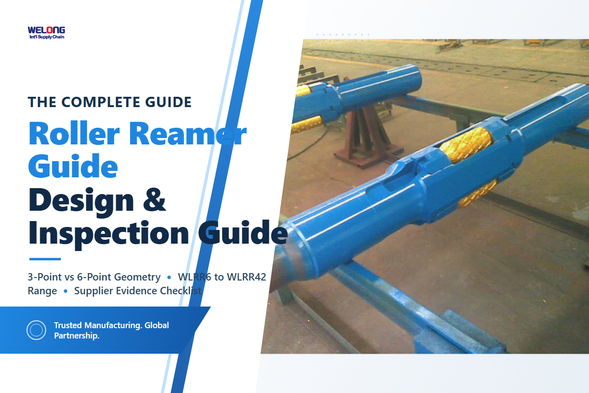
A roller reamer is a drilling reamer used in the oil and gas industry to condition an existing wellbore while drilling oil and gas wells. It uses rotating cutters, so rolling contact distinguishes it from fixed-contact hole-conditioning tools. This guide explains the main operating principles, design families, document checks, and wear signs that should be reviewed with the tool supplier and drilling team.
Roller reamers use rolling cutters to condition a borehole. Contact-point count and gauge-control method create different engineering trade-offs; neither is a universal upgrade. Select the configuration against the BHA, formation, required hole condition, and the supplier’s documented operating limits.
Key Takeaways
- Rolling cutters can reduce sliding contact compared with fixed-contact designs, but actual performance depends on the tool and operating conditions.
- Three-point and six-point layouts create different load-sharing and packaging trade-offs; neither is universally better.
- Bearing and seal problems can develop progressively, so inspection criteria should be agreed before the run.
- API Spec 7-1 and ISO 9001 address different subjects. Verify the exact product documents rather than relying on a broad marketing label.
- Although a roller reamer can help condition a localized restriction, it cannot replace trajectory management for a dogleg.
What Is a Roller Reamer? Precise Terminology vs Hole Opener, Stabilizer, and Underreamer
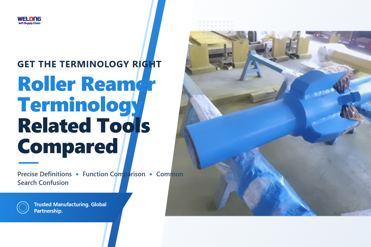
In operation, a roller reamer uses rotating cutters to condition the wellbore and maintain gauge around the selected BHA position. By contrast, a drilling stabilizer uses fixed blades primarily to centralize the assembly. Meanwhile, a hole opener enlarges a pilot hole, while an underreamer expands after passing through a restriction. Those mechanisms overlap within the wider downhole drilling tools category but are not interchangeable.
API Spec 7-1 is relevant to listed rotary drill-stem elements and stabilizers; its published scope does not make a roller reamer an API 7-1 product. If a supplier cites the standard, ask whether the claim applies to a covered connection or component, and request the exact conformity record.
Start the requisition with the required hole condition, BHA position, formation, connection, and service limits. Then match those requirements to the supplier’s drawing and operating instructions instead of selecting a tool from a shared product name.
Mechanism: How Roller Reamer Bearings Influence Torque and Downhole Vibration
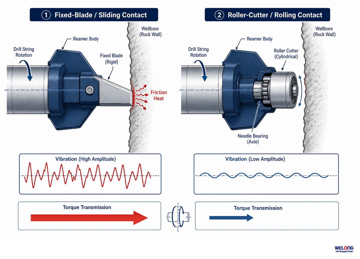
Rolling contact versus continuous sliding contact is the relevant physical distinction. Compared with a comparable fixed-contact design, a rolling cutter may reduce resistance transmitted to the drill string; torque, vibration, and heat still depend on the tool, formation, drilling fluid, and operating program. Any torque reduction or smoother drilling result must therefore be treated as application-specific rather than guaranteed.
Reaming action and cutting action occur at the rolling interface. On the reamer body, a reamer pin and reamer cutter are secured by a manufacturer-specific cutter retention system so the cutter can rotate under load as part of the bottom hole assembly. Drawings may label the hardware as a locking device for the reamer, a device for the reamer pins, or reamer pins on each body; some designs may also show socket head cap screws or a large diameter pin. If a drawing uses the term cross pin, verify its exact retention function rather than assuming the label is interchangeable. These labels are not universal specifications. Verify the drawing, function, material, and inspection criteria for the proposed tool. U.S. roller-reamer bearing patent literature also describes the general rolling-contact concept.
Plan inspection criteria before the run; a progressive wear mechanism is easier to manage than an unexpected failure.
Operational reminder
Research on rolling-contact drilling systems discusses torsional oscillation and whirl as design considerations. Those findings cannot be converted into a universal result for a particular roller reamer. Placement in a BHA and any expected benefit should therefore be confirmed against the planned drilling program and the supplier’s guidance.
Welong Roller Reamer Type Spectrum: 3-Point vs 6-Point Contact Geometry
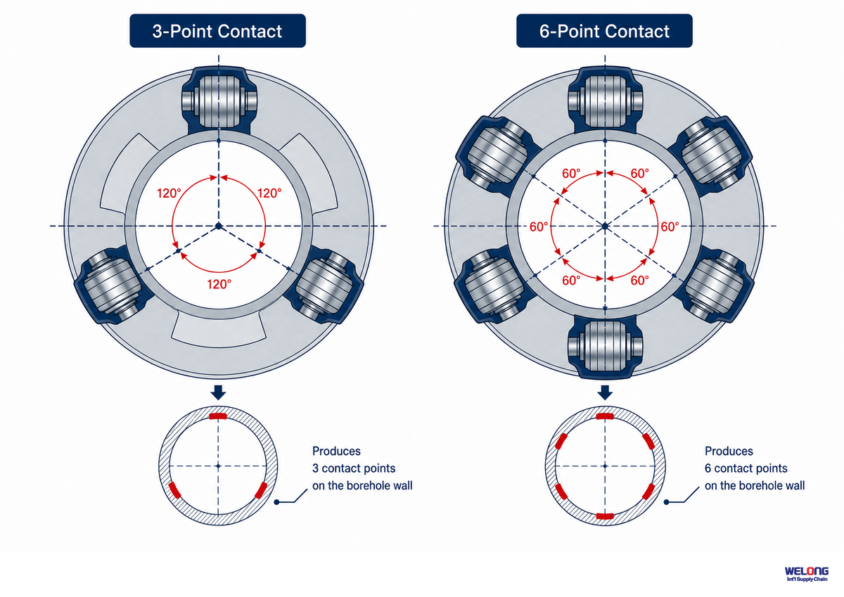
Three-point and six-point roller reamers distribute the total enlargement load over different contact areas. Here, three points versus six describes the interplay of per-cutter contact pressure, the penalty for losing a single cutter to wear, suitable formations, and available diameters—not a different operating principle. Soft formation alone does not make a three-point layout correct, just as hard formation alone does not make six points correct. These are engineering choices, not quality tiers.
Contact geometryCompare cutter count and layout
Gauge controlFixed or expandable, by design
Material documentsVerify against the proposed tool
With fewer contact points, each cutter can represent a larger share of the contact layout; with more points, the layout and service scope become more complex. Load distribution in a real well is not perfectly even, so cutter count alone does not establish suitability. Selection should follow the tool specification and BHA design, consistent with the contact-geometry variations described in reamer design patent filings.
| Comparison Category | 3-Point Configuration | 6-Point Configuration | Limitations / Not suitable for |
|---|---|---|---|
| Contact points per revolution | 3 roller cutters | 6 roller cutters | Neither replaces a stabilizer’s centering function |
| Nominal per-cutter load share | Higher, if load is evenly distributed | Lower, if load is evenly distributed | Actual field load is rarely perfectly even on either config |
| Effect of single-cutter wear | Single-cutter wear may affect a larger share of the contact layout | The effect depends on the actual layout and remaining cutters | Not a substitute for a documented inspection plan |
| Typical diameter range fit | Smaller to mid-range hole sizes | Larger-diameter reamers | Diameter fit is manufacturer-specific — confirm on the spec sheet |
| Reaming/stabilizing behavior | Simpler load path | More contact points available for load sharing on larger-diameter layouts | Not validated as universally superior across all diameters |
| Body/pin/locking-device scope | Fewer cutter assemblies | More cutter assemblies | Confirm the supplier’s inspection scope for the actual tool |
| Mud flow / cleaning path around body | Wider flow channels between points | Narrower flow channels between points | Not suitable where hole-cleaning margin is already tight |
| Rebuild/spare-parts scope | Fewer cutter/pin/locking-device sets to rebuild | More sets, more rebuild line items | Not suitable for operators wanting minimal spare-parts SKUs |
| Best-fit application | Standard-diameter directional intervals | Large-diameter, abrasive-formation intervals | Confirm against actual formation and BHA design, not this table alone |
Selection should not follow which contact count sounds better; it should follow the documented design that fits the required hole condition, BHA, formation, and service plan. Review the proposed tool’s dimensional drawing, material records, cutter layout, and operating limits with the supplier before making a selection.
Welong Public Catalog Snapshot: 12 Three-Cutter Models
Welong’s current public catalog lists 12 three-cutter models from 6 in to 42 in, with AISI 4145H, AISI 4145H MOD, and AISI 4330V shown as body-material options. This table is a first-party catalog snapshot, not a field-performance comparison. Confirm the selected row, material grade, and connection on the quotation and controlled drawing. Use the roller reamer model and connection selector to organize the first pass, while the formation-matched cutter advisor frames the formation questions that still require engineering confirmation. Metric equivalents below are calculated at 25.4 mm per inch and rounded to the nearest 0.1 mm; the published inch values remain controlling.
| Model | Hole size | Connection | Fishing neck | ID | Overall length | Blade length |
|---|---|---|---|---|---|---|
| WLRR42 | 42 in (1066.8 mm) | 8-5/8 REG Box × Pin | 11 in (279.4 mm) | 3 in | 118 in to 130 in | 24 in (609.6 mm) |
| WLRR36 | 36 in (914.4 mm) | 7-5/8 REG Box × Pin | 9.5 in (241.3 mm) | 3 in | 110 in to 120 in | 22 in (558.8 mm) |
| WLRR28 | 28 in (711.2 mm) | 7-5/8 REG Box × Pin | 9.5 in (241.3 mm) | 3 in | 100 in to 110 in | 20 in (508.0 mm) |
| WLRR26 | 26 in (660.4 mm) | 7-5/8 REG Box × Pin | 9.5 in (241.3 mm) | 3 in | 100 in to 110 in | 20 in (508.0 mm) |
| WLRR24 | 24 in (609.6 mm) | 7-5/8 REG Box × Pin | 9.5 in (241.3 mm) | 3 in | 100 in to 110 in | 20 in (508.0 mm) |
| WLRR22 | 22 in (558.8 mm) | 7-5/8 REG Box × Pin | 9.5 in (241.3 mm) | 3 in | 100 in to 110 in | 20 in (508.0 mm) |
| WLRR17 1/2 | 17.5 in (444.5 mm) | 7-5/8 REG Box × Pin | 9.5 in (241.3 mm) | 3 in | 90 in to 100 in | 18 in (457.2 mm) |
| WLRR16 | 16 in (406.4 mm) | 7-5/8 REG Box × Pin | 9.5 in (241.3 mm) | 3 in | 90 in to 100 in | 18 in (457.2 mm) |
| WLRR12 1/2 | 12.5 in (317.5 mm) | 6-5/8 REG Box × Pin | 8 in (203.2 mm) | 2.8125 in | 79 in to 90 in | 18 in (457.2 mm) |
| WLRR12 1/4 | 12.25 in (311.2 mm) | 7-5/8 REG Box × Pin | 8 in (203.2 mm) | 2.8125 in | 79 in to 90 in | 18 in (457.2 mm) |
| WLRR8 1/2 | 8.5 in (215.9 mm) | 4-1/2 IF Box × Pin | 6.75 in (171.5 mm) | 2.8125 in | 65 in to 72 in | 16 in (406.4 mm) |
| WLRR6 | 6 in (152.4 mm) | 3-1/2 IF Box × Pin | 4.75 in (120.7 mm) | 2.25 in | 60 in to 66 in | 16 in (406.4 mm) |
Illustrative scenario: a procurement team comparing WLRR6 with WLRR42 is not comparing a small and large version of an otherwise identical assembly. Public rows change from a 6 in hole size and 3-1/2 IF connection to a 42 in hole size and 8-5/8 REG connection. That difference changes the connection, envelope, handling, and document package that must be checked; it does not prove a field-performance advantage.
Fixed-Gauge vs Expandable Design: The Actuation Principle Behind Adjustable Gauge
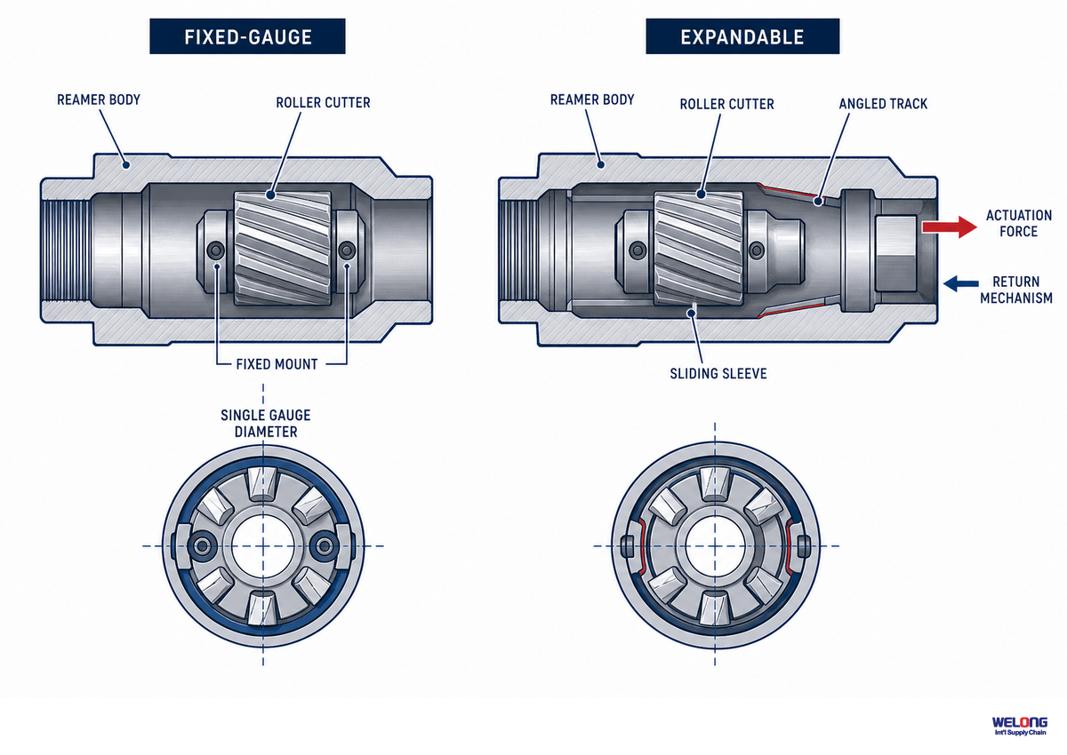
Fixed-gauge and expandable reamers use different mechanical approaches. Fixed-gauge tools are manufactured to a stated diameter. Expandable designs can use drilling-fluid pressure and a mechanical actuator to move their cutting structure after the tool has passed a restriction.
Patented expandable designs describe approaches such as a pressure-driven sleeve or piston-like cutter arms. Pressure, travel, locking method, and default position vary by tool design; obtain those values from the supplier’s current specification instead of applying a generic operating range.
Fixed-Gauge Design
- Gauge is set by the manufactured tool geometry
- Does not rely on a downhole actuation sequence
- Requires a different tool when the required gauge changes
Expandable Design
- Gauge change is produced by the tool’s documented actuation mechanism
- May pass a restriction in a retracted position, depending on the design
- Requires review of the actuator, retention method, and service instructions
For expandable designs, the retention method matters alongside the actuator. An engineer should ask for the maximum reaming diameter, the secondary locking device, how the cutting structure is retained under documented operating conditions, and what happens if the actuation sequence is interrupted. Related mechanisms are covered in gauge-actuation patent filings.
API Spec 7-1 Scope Boundary: What Buyers Should Verify
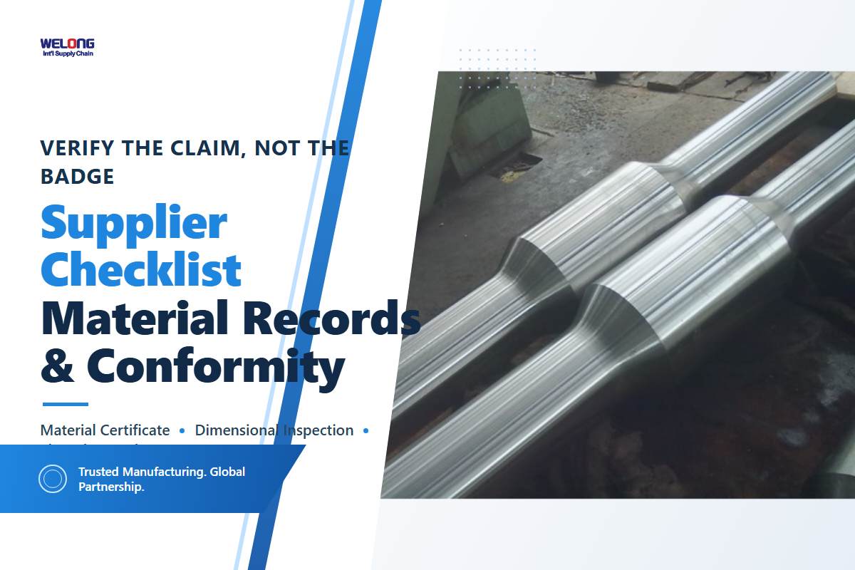
API Spec 7-1’s published scope lists rotary drill-stem elements such as drill collars, heavy-weight drill pipe, subs, connections, and stabilizers. It does not list roller reamers as a finished-product category. Suppliers therefore should not use the standard’s existence alone as proof that a roller reamer is an API 7-1 certified product.
When API 7-1 appears in a quotation, ask which covered element the claim applies to. Useful evidence may include the connection specification, dimensional drawing, material record, inspection report, and a statement that identifies the exact scope of conformity. Acceptance criteria and tolerances must come from that controlled documentation, not from a generic article.
📐 Engineering Note
Government and technical references can provide context for drilling operations and tool reliability, but they do not replace the product-specific requirements in the applicable standard, drilling program, or supplier records.
For any standards claim, verify the cited edition against the API standards addenda and errata, the covered component, and the records supplied for the actual tool. Labels alone are not enough for a purchasing or engineering decision.
Quality Systems: ISO 9001 Inspection and Traceability in Reamer Production
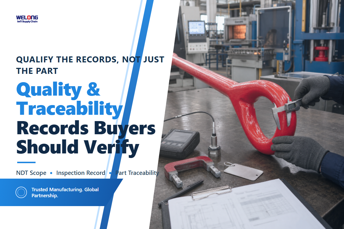
ISO 9001 is a quality-management-system standard. It can support documented processes and traceability, while non-destructive testing (NDT) may be used in a supplier’s inspection plan. Neither statement proves that every component of every reamer received a particular inspection; the purchaser should request the applicable records for the proposed tool.
Marketing shorthand such as “parts are inspected” is not enough. Useful supplier review asks which components are inspected, whether the device for the reamer pins is included, which methods are used, what acceptance criteria apply, and which material or service records accompany the tool. Use the roller reamer RFQ builder to capture those questions. Public sources available for this guide do not establish a universal inspection sequence, retention period, or re-inspection interval for roller reamers.
💡 Pro Tip
When a supplier cites ISO 9001, ask which components receive NDT inspection, at which stage, and which records will be delivered with the tool. Set any service interval from the supplier’s instructions and the well conditions, not from a generic interval.
An ISO 9001 claim concerns a quality-management system, not a stand-alone product specification. It should be considered alongside applicable drawings, inspection records, connection requirements, and the supplier’s stated product scope.
Application Context: Gauge Maintenance and Casing Clearance in Directional Drilling
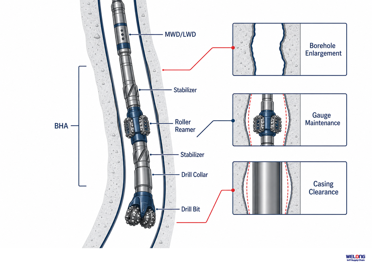
In directional drilling applications, hole condition created during drilling affects the operations that follow. Ledges, key seats, and under-gauge sections can increase the risk of drag or restriction when the assembly or casing passes through the same interval.
In a directional drilling BHA, a roller reamer may be positioned near the bit or near LWD tools to condition the hole while drilling and maintain the planned hole gauge. Its placement and expected effect depend on the BHA, trajectory, formation, drilling fluid, and operating program. Use the near-bit or string placement quick check to organize the questions, then have the drilling team confirm the answer. Government drill-stem testing requirements likewise show why operational procedures are well-specific rather than universal roller-reamer settings. Gauge irregularities can complicate later operations, including casing running, so the tool selection and acceptance criteria should be established for the specific well rather than by using a generic inclination, speed, or pressure threshold.
The practical value is therefore downstream as well as immediate: the drilling team is trying to leave a borehole condition that supports the planned casing and completion program. Local conditioning with a roller reamer can assist, but it cannot correct a poor trajectory plan.
Bearing-Seal Wear-to-Failure Anatomy
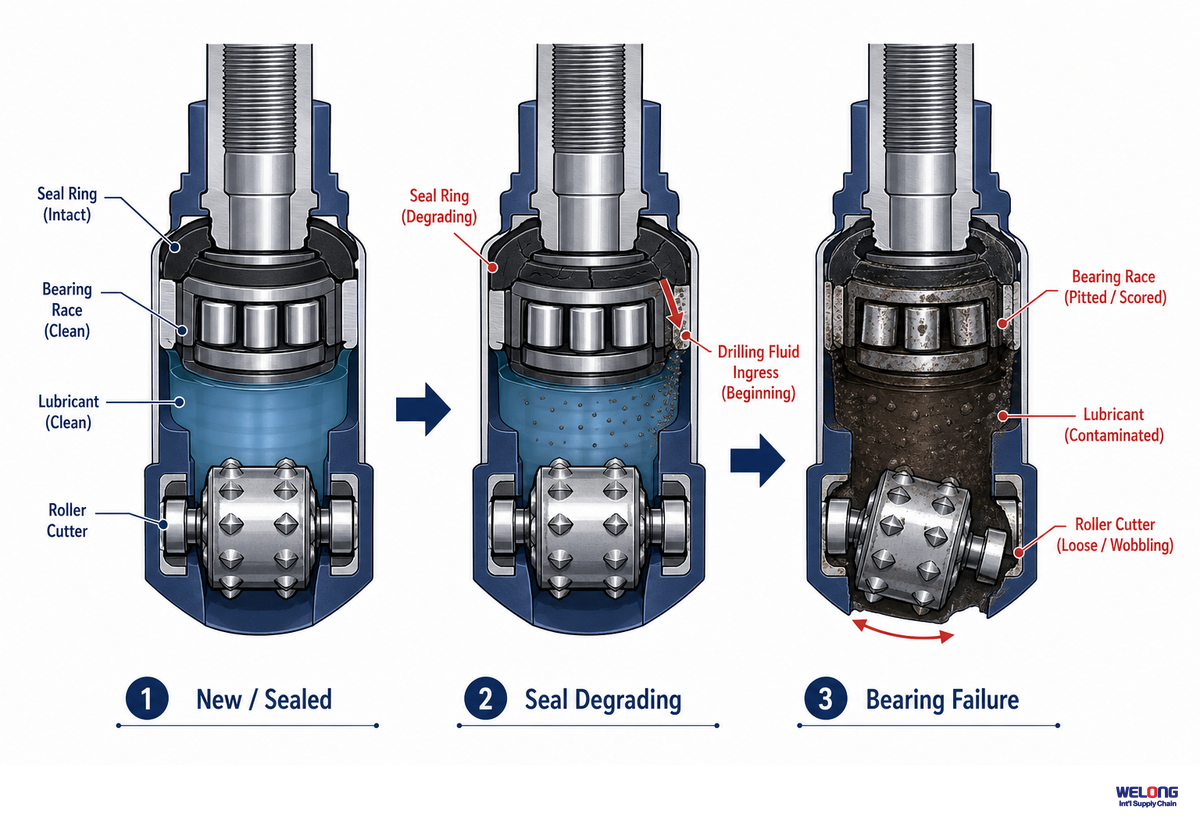
Bearing and seal damage can progress from early seal wear to fluid or solids ingress, lubricant contamination, raceway damage, cutter looseness, and eventual seizure. Its sequence and inspection criteria depend on the actual bearing design, mud system, loading, and supplier instructions.
Knowing this progression is often what separates a planned repair from an unscheduled trip for cause. Each state below builds on the previous one, and the sooner a condition is spotted, the less expensive—and usually more routine—it is to address.
| Stage | Visible / Detectable Sign | Underlying Mechanism | Limitations / Not suitable for |
|---|---|---|---|
| 1. Seal micro-wear | Not visible without close inspection | Normal abrasive contact begins thinning the seal lip | Not detectable from surface drilling parameters alone |
| 2. Seal breach / mud ingress | Slight discoloration at seal boundary on inspection | Seal lip no longer excludes drilling fluid solids | Requires physical inspection to catch — no downhole sensor on most tools |
| 3. Lubricant contamination | Grease sample shows abrasive solids on teardown | Ingressed solids mix into the bearing lubricant | Only confirmable at teardown, not mid-run |
| 4. Lubricant washout | Reduced grease volume/consistency at teardown | Contaminated lubricant loses film strength and washes out | Progression rate varies by mud system — not a fixed timeline |
| 5. Raceway surface wear (spalling onset) | Surface pitting visible on bearing raceway | Metal-to-metal contact begins without lubricant film | Not reliably detectable without pulling the tool |
| 6. Bearing play increase | Measurable radial play on inspection | Worn raceway surfaces increase clearance | Not measurable while the tool is downhole |
| 7. Cutter wobble / off-axis loading | Uneven wear pattern on cutter face | Excess bearing play lets the cutter load off-axis | Accelerates remaining stages once it begins |
| 8. Accelerated raceway wear | Rapidly worsening play between inspections | Off-axis loading compounds wear rate | Narrow window remains before Stage 9 |
| 9. Bearing seizure / cutter lock-up | Cutter stops rotating; torque spike at surface | Raceway wear progresses to full mechanical binding | Usually requires an unplanned trip to address |
This table is not a fixed replacement schedule. Wear rate and acceptable service condition depend on the mud system, formation, operating program, tool design, and supplier criteria. Use physical inspection findings and the documented service limits for the actual tool to decide whether it can remain in service. General drilling-tool reliability research, including this Department of Energy technical report, supports the need to manage progressive wear, but does not establish a universal roller-reamer pull limit.
Field Failure Mechanisms: Root Causes of Dogleg Severity and Key-Seat Wear
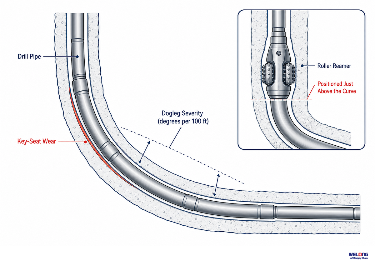
Dogleg severity and key-seat wear arise from different aspects of borehole geometry and string contact. Repeated contact can wear the wellbore wall and form a key seat. Local conditioning with a roller reamer may help at a restriction, but it does not replace trajectory management or resolve the root cause of a directional problem.
Intervals through a hard formation, abrasive interval, or side-loaded section can increase tool wear. If the well path begins to deviate from the planned trajectory, treat that as a directional-drilling issue rather than proof that the reamer has failed. Drilling-fluid properties, alignment, rotational program, and the actual BHA are relevant considerations, with drilling-fluid fundamentals documented in this Ocean Drilling Program technical note. Establish torque, trajectory, and pull criteria in the drilling program and follow the supplier’s response guidance; this article does not set universal thresholds.
Do
- Match reamer size and configuration to the well design before running it
- Track rotational speed against the formation’s actual hardness profile
- Confirm mud lubrication properties before a dogleg-heavy interval
- Pull and inspect on a schedule tied to formation abrasiveness, not a fixed calendar
Don’t
- Run a reamer type mismatched to the formation to save a trip
- Ignore a rising torque trend through a known dogleg interval
- Assume lubrication is adequate without checking mud properties
- Treat key-seat wear as solved without addressing the trajectory that caused it
Roller reamers can be part of the response to a localized hole-condition problem, but a persistent trajectory issue requires a directional-drilling decision. Treat the reamer as one element of the BHA and operating plan, not as a stand-alone cure.
Roller Reamer vs Automotive Ridge Reamer: Clearing Up a Common Search Confusion
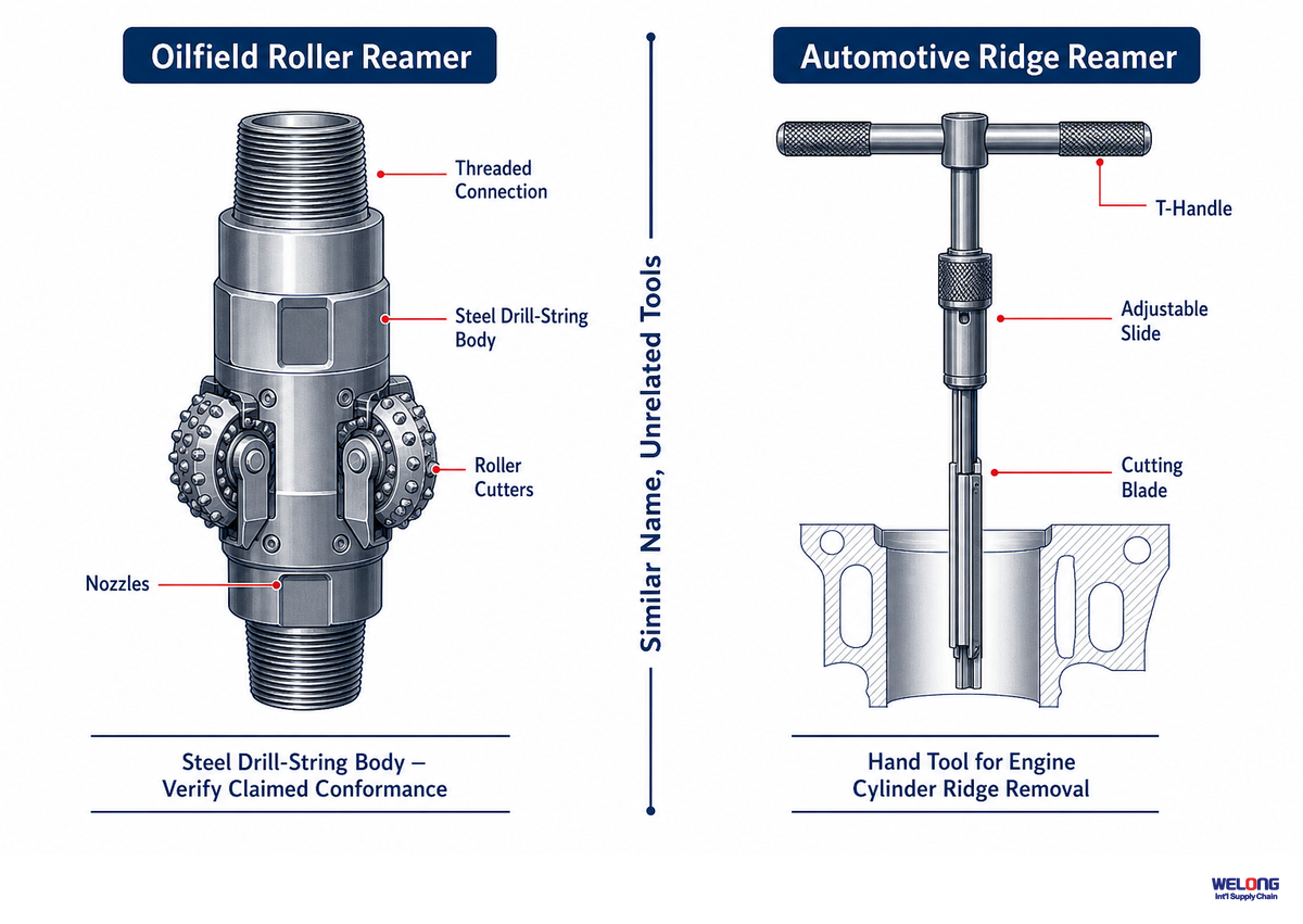
Search results sometimes mix oilfield roller reamers with automotive ridge reamers used to remove cylinder ridges. They share the word “reamer,” but their designs, applications, and markets are different.
An automotive ridge reamer is a separate workshop tool used during engine service. It shares the word “reamer” with an oilfield roller reamer, but the operating environment, construction, and selection criteria are different.
For a drilling-tools search, use BHA, wellbore, and roller cutter terminology to distinguish the oilfield tool from automotive products.
Evidence Boundary: Hybrid Bits and Smart BHA Tools Are Not Roller Reamers
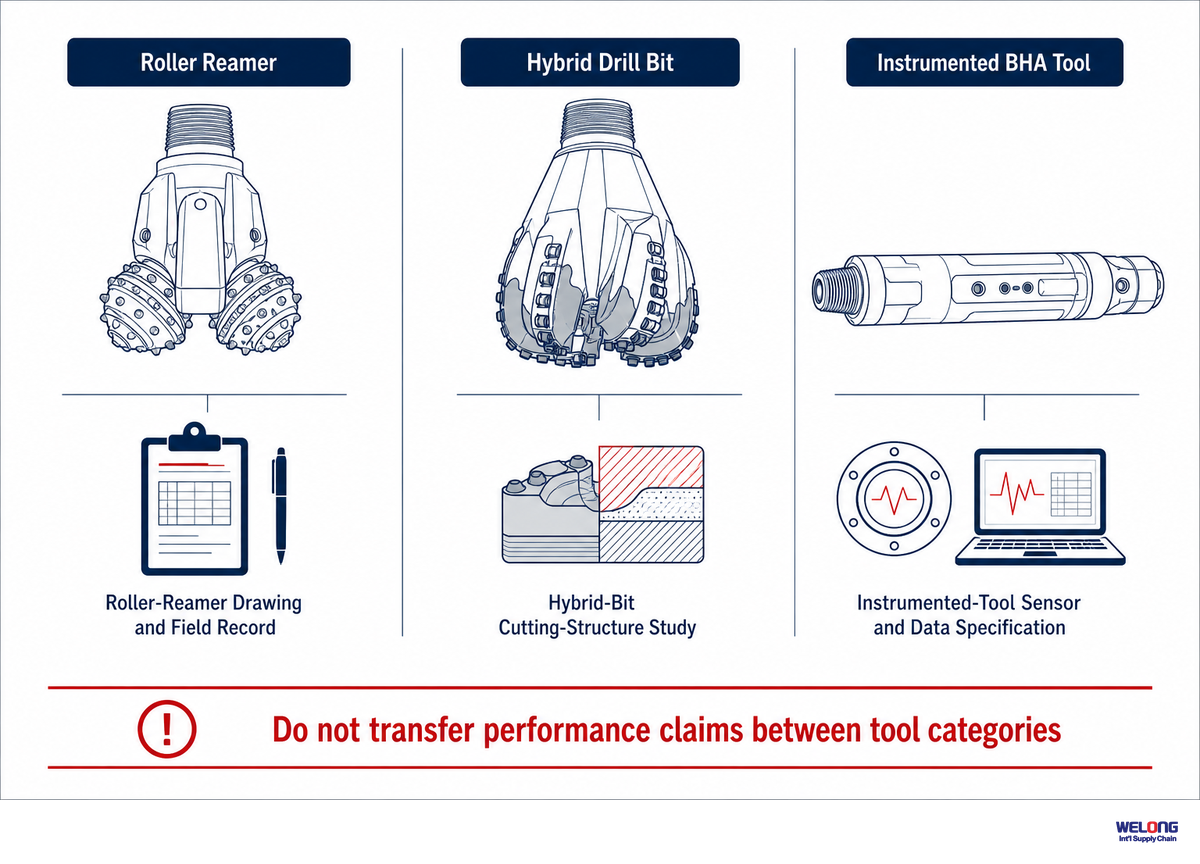
Roller-cone/PDC hybrid research concerns drill bits that combine different cutting structures at the bit face. Instrumented BHA tools concern measurement and control. Neither category is evidence that a roller reamer delivers the same vibration result, telemetry capability, or market trend.
Published hybrid-bit vibration research can help an engineer frame questions about torsional behavior, but its results should not be transferred to a roller reamer without product-specific test or field data.
Key takeaway
Separate technology scouting from product evidence. Ask the roller-reamer supplier for data generated on the proposed tool and application.
Frequently Asked Questions
Q: What is the function of a reamer?
A reamer conditions an existing wellbore; the exact function may be gauge maintenance, local enlargement, or removal of ledges and key seats for the planned operation.
Here, a roller reamer uses rotating cutters to work against the borehole wall at its BHA position. Expected results depend on the tool geometry and drilling program, so the requisition should state the required hole condition rather than assume every reamer enlarges the hole beyond bit size. Supplier drawings and operating instructions define the usable gauge and service limits. Confirm whether the goal is gauge maintenance or planned enlargement.
Q: What are the different types of reamers?
Reamers are commonly grouped by their contact geometry and gauge-control mechanism: fixed-gauge roller designs, expandable reamers, and other hole-opening or conditioning tools with different cutting structures.
Product terminology varies by manufacturer. Use the drawing and operating description to distinguish a fixed-gauge roller reamer from an expandable reamer, underreamer, stabilizer, or hole opener. Within roller reamers, suppliers may also describe three-point and six-point contact layouts. Required hole condition and specific BHA design should control the choice. Confirm the intended function before comparing supplier terminology.
Q: What is the structure and principle of a roller reamer?
A roller reamer carries rotating cutters on a drill-string body so the contact at the borehole wall is rolling rather than continuously sliding during the run.
Each cutter uses a bearing, axle or pin, retention method, and seal arrangement defined by the manufacturer. Rotation allows the cutters to condition the wall while the body remains part of the BHA. Buyers should review the cutter layout, retention drawing, bearing service instructions, and inspection limits because those details are not universal for service planning.
Q: Why use a reamer instead of a drill bit?
A drill bit cuts new hole through formation, while a reamer is selected to condition or enlarge an existing borehole section where the tool design and drilling program call for it.
Drill bits are the primary formation-cutting tools. Reamers are added when the drilling program needs gauge maintenance, local hole conditioning, or another defined function above the bit. They do not replace correct bit selection or trajectory control.
Q: Can I run a roller reamer in the same drilling assembly as a stabilizer?
Roller reamers and stabilizers can be used in the same BHA when the design, tool spacing, and drilling program require both hole conditioning and stabilization functions.
A roller reamer and a stabilizer have different intended functions, but their compatibility is BHA-specific. Confirm spacing, gauge, operating limits, and the supplier’s recommendations before running them together.
Decision Framework & Related Reading
This guide explains general engineering concepts and is not an RFQ or selection document. For product-specific information, consult the roller reamer selection guide and the formation-matched design article listed below.
Editorial Scope
This guide addresses recurring mechanism-level questions about rolling contact, gauge control, document review, and wear planning. It does not state a manufacturer-specific inspection schedule or replace the records supplied for a particular tool.
References & Sources
- 43 CFR § 3172.9, Drill-Stem Testing Requirements U.S. Department of the Interior, Bureau of Land Management (eCFR)
- API Spec 7-1, Rotary Drill Stem Elements — official scope page American Petroleum Institute
- API Standards Addenda and Errata American Petroleum Institute
- Drill-Stem Element Technical Report U.S. Department of Energy, Office of Scientific and Technical Information
- Ocean Drilling Program Technical Note 31: Drilling Fluids Texas A&M University
- Applications, Results, and Lessons Learned From Using Roller Reamers in Hard, Abrasive Formations, The FORGE Project OnePetro / Society of Petroleum Engineers
- Stabil Drills’ Ghost Reamer Tool for Shale Drilling Eliminates Wiper Trips Drilling Contractor, International Association of Drilling Contractors (IADC)
- US Patent 7,900,717 B2, Expandable Reamer Apparatus United States Patent and Trademark Office
- US Patent 6,991,046 B2, Expandable Reamer Apparatus United States Patent and Trademark Office
- Hybrid Roller-Cone/PDC Bit Vibration Performance (peer-reviewed) ScienceDirect / Elsevier
Related Articles
- Roller Reamer Selection Guide full buyer-facing specification and RFQ guide
- Roller Reamer vs Hole Opener vs Fixed-Blade Stabilizer function-first tool comparison
- Top 5 Roller Reamer Designs and Their Applications formation-matched design recommendations
- About Welong manufacturing background and quality-system overview
![Choke & Kill Hose: [Field Guide]](https://welongoiltools.com/wp-content/uploads/2026/07/choke-kill-hose-guide-featured-1-150x150.png)