Get in touch with Welong Company

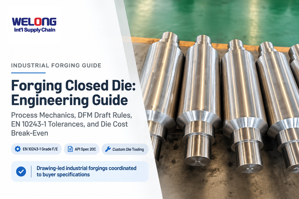
When forging closed die parts, shops press a heated metal billet inside matched custom die cavities. That confined pressure drives directional grain flow along the part contour. Engineers compare upfront tooling cost against tighter as-forged tolerances and lower CNC machining time. Independent vendor benchmarks place custom steel dies at $5,000–$50,000+ (WALKSON) and $5,000–$80,000 (MFG SOLUTION), while wider industrial sets span $3,000–$500,000+ (China Metal Supply). Recurring production volume amortizes the die investment and lowers total cost per part.
Back pressure at the flash land restricts outward metal flow and drives metal into deep die cavities. There is a comparison of closed-die forging advantages to open-die forging, casting and bar machining. You will also find DFM draft rules, alloy steel versus aluminum temperature bands, EN 10243-1 steel-forging tolerances, and ASTM B247 requirements for aluminum-alloy forgings. The guide covers press selection, defect-to-NDT matching, and an oilfield RFQ specification package. Engineers sourcing custom industrial forgings coordinated to buyer drawings can lock manufacturing route and inspection terms before releasing tooling.
What Is Closed-Die Forging and How Does the Impression Process Work?
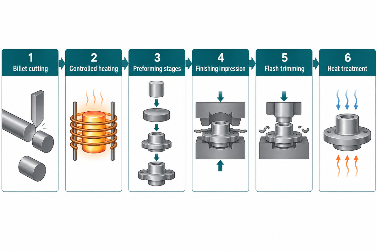
Closed-die forging is a form of solid-state metal forming process. In hot closed-die forging, operators heat the metal workpiece above 0.6 times its absolute melting temperature (0.6 Tm in Kelvin) before pressing it in matched dies. Grain flow is formed during closed-die forging. Fine-grained recrystallized structure is formed in the forged part as a result of the high compressive force during the closing of the dies (The Open University Manupedia).
The upper die closes against the bottom die to squeeze the metal in the mold. Excess material then enters a thin perimeter gap called the flash land. A thin metal strip is in the gap and cools quickly. It restricts outward metal flow and creates back-pressure. Back-pressure forces hot metal to fill the die across deep ribs, corners, and thin webs. Remaining extra metal flows into the flash gutter.
Six Stages of the Closed-Die Forging Process
- Billet cutting starts the cycle: bar stock is sheared or sawed to a controlled gross weight. The gross weight accounts for finished part volume, allowance for flash, and scale lost from heating.
- Controlled heating brings the raw material to its forging temperature in induction coils or gas furnaces, with fast induction cycles helping limit surface scale.
- Preforming stages (fullering, edging, bending, and blocking) redistribute mass along the billet axis so metal fills the finishing cavity without folding.
- The piece of metal is pre-formed to fit the desired shape and excess metal is pushed out to the periphery.
- Flash trimming shears excess material along the parting plane in a trimming die, while a piercing punch removes internal webs either hot or cold.
- Heat treatment and/or cleaning finishes the forging through normalizing, quenching and/or tempering and solution annealing.
Grain Flow Mechanics and Flash vs. Flashless Terminology
Solid metal deforms plastically instead of melting into a mold. With sufficient compressive stress and deformation ratio, hot forging breaks down cast ingot structure and helps close internal voids. It also aligns elongated grain structure along the direction of metal flow. In aluminum comparisons, Extra Forge reports 20–30% higher mechanical strength than cast or extruded parts. Tensile strength advantages reach up to 80 MPa over cast aluminum.
In the market, “closed-die forging” and “impression-die forging” are often recognized as synonyms. From a metallurgical perspective, the difference is clear. In impression-die forging, some flash is unavoidable around the parting plane. True closed-die (flashless) forging encloses the billet inside a sealed cavity permitting virtually no excess metal to flow out (CarboForge Glossary). Flashless tooling requires higher press loads and exact control over billet volume. On the other hand, some flexibility in the weight of billet is allowed in Flash impression dies forging, and this typically results in a filled cavity.
“Forged alloys have better strength, ductility and structural integrity than their cast counterparts because of the fine-grained recrystallized structure obtained by high percentage deformation at temperatures >0.6 Tm and grain flow achieved in the component.”
Buyers are frequently concerned about heating excess flash to then remove it. In traditional impression dies, removing the flash land eliminates the hydrostatic back pressure required to fill thin ribs.
Open-Die vs. Closed-Die Forging, Casting, and CNC Machining
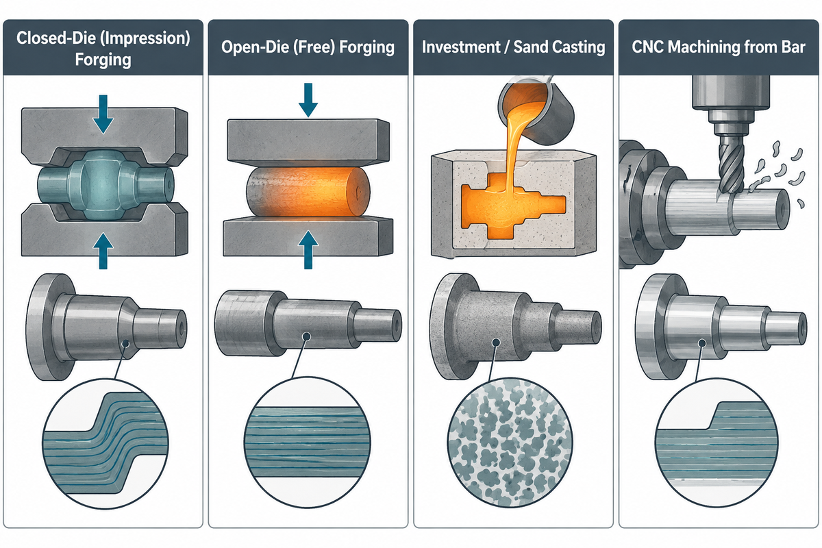
Open-die forging (also known as free forging) compresses heated stock between flat or simple V-shaped dies without enclosing sideways metal flow. It fits large, heavy, low-volume shafts and blocks. Closed-die forging is the forging method that confines metal in custom cavities, forming complex shapes with better repeatability and less precision machining at medium-to-high production volume (Canton Drop Forge).
In deciding between open and closed die processes, casting, or bar machining, four factors influence the decision. These factors are tooling amortization, cyclic fatigue loads, part weight, and the volume of chips removed. Closed-die forging also differs from die casting. With die casting, a nonferrous metal is cast in a steel die with the risk of gas or shrinkage porosity. Closed-die forging compresses hot solid metal and achieves superior mechanical properties with shock loads.
| Decision Criterion | Closed-Die (Impression) Forging | Open-Die (Free) Forging | Investment / Sand Casting | CNC Machining from Bar |
|---|---|---|---|---|
| Die / Tooling Investment | High ($5,000–$50,000+ WALKSON; $5,000–$80,000 MFG SOLUTION) | Minimal (standard flat, round, or V-shaped dies) | Low-to-moderate (wax injection die or sand pattern) | Zero custom forging tooling (fixtures only) |
| Geometric Complexity | Complex 3D ribs, bosses, flanges, non-axisymmetric shapes | Simple shapes: shafts, bars, discs, rings, blocks | Highest complexity including hollow internal passages | High precision, limited by tool reach and chip removal cost |
| As-Formed Tolerance | Depends on measured dimension, mass, shape complexity, alloy, and tolerance class; EN 10243-1 Grade F/E governs applicable steel forgings (Open University cites +1.5/−0.5 mm on 0.5–1 kg flash steel and +0.3–0.4 mm on Hatebur-type flashless hot formers as process benchmarks, not whole-part limits) | Coarse (requires full-surface finish machining stock) | Moderate-to-tight (investment) / coarse (sand) | Tightest finished accuracy (depends on part size, tooling, and ISO 286-1 IT specification) |
| Grain Flow & Strength | Continuous contour grain flow; forged aluminum reaches 20–30% higher mechanical strength vs. cast/extruded (Extra Forge) | Directional axial/radial grain; refined by high reduction | Isotropic dendritic structure; shrinkage/gas porosity risk | Straight rolled grain cut across fillets and shoulders |
| Typical Part Weight Scope | Grams to 250 kg under EN 10243-1 (5–520 kg at dedicated shops like Longrui; up to 1,500 lb at MTS Forge) | Tens of kilograms up to multi-ton heavy forgings | Grams to multi-ton housings | Grams to medium parts where stock removal stays low |
| Material Waste Form | Trimmed flash and scale (minimal CNC chips) | Heavy machining stock turned into swarf | Sprues, risers, and gates (remeltable) | High chip loss on contoured geometries |
| Secondary Machining | Selective (mating bores, threads, sealing faces only) | Extensive full-profile turning and milling | Light-to-moderate on critical datums | Full-profile machining from solid bar or plate |
| Design Change Agility | Low (geometry freeze required before die sinking) | High (dimensions adjusted on press/CNC) | Moderate (pattern modification needed) | High (program-only updates work when existing stock, cutters, fixtures, and machine access fit the revised geometry) |
| Typical Economic Volume | Recurring medium-to-high runs (100–500 pcs/yr per China Metal Supply; 500–1,000 pcs/run rule per MFG SOLUTION) | Single piece to low-volume heavy runs | Low-to-high where hollow geometry rules out forging | Prototypes, low lots, or simple cylindrical profiles |
Part geometry can override simple batch size rules. In an Eng-Tips discussion on forging a low-carbon steel hub, an open-die well head forge declined the drawing and steered the engineer to a closed-die shop. Machining contoured pockets from an oversized open-die blank costs more than amortizing a dedicated die. For low-volume blocks review open-die forging tolerances and custom forged shafts. When evaluating mixed part families before quoting, use forging route selection criteria for custom drawings.
Flashless forging removes flash waste only when billet volume and die alignment are tightly controlled. Trenton Forging notes that the complexity of tooling pattern or shape controls most commercial flashless forging to symmetrical gears and rounds. Other specialized lines are also capable of producing complex flashless forging. FIA Case Study No. 10 describes hot closed-die flashless forging of connecting rods, which eliminates trimming.
Types of Forging Dies and Closed-Die Design Guidelines (DFM)
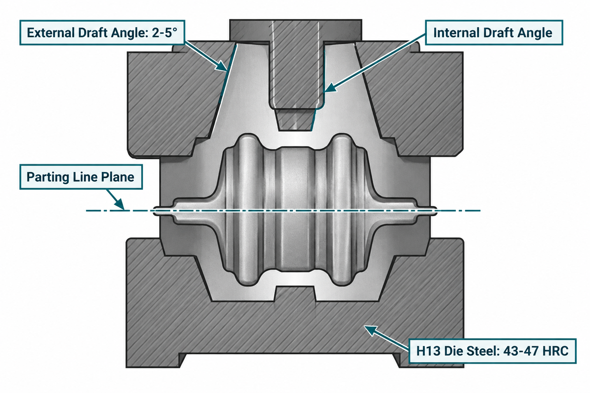
Closed-die forging and tooling rarely use one block with a single pocket. As defined in the CarboForge Glossary, forging operations combine preforming cavities (fullering, edging, bending and blocking impressions), a finishing impression, and separate trimming, piercing or coining dies. Toolmakers machine hot-forging dies from hardened hot-work tool steels such as AISI H13, which is commonly treated as equivalent to DIN 1.2344 and JIS SKD61 ( Haoyuan Special Steel).
Primary Forging Die Types in Multi-Stage Tooling
- Single-impression dies suit symmetrical parts finished in one cavity. Asymmetrical parts often undergo preforming stages such as fullering, edging, bending, and blocking before finishing. Preforming stages are either combined in one bolster or split across a number of presses.
- Flash impression dies machine a calibrated flash land and relief gutter along the parting line to drive cavity fill. Flashless precision dies enclose the workpiece in a sealed die and punch chamber.
- When standard accuracy of a forming or forging doesn’t meet the required flatness or thickness, it’s trimmed or coined to the final desired dimensions. This is achieved by piercing or coining punches that trim or remove excess metal or webs within the forging.
- Specialty tooling includes upset forging and roll forging dies. The former is used to gather bar-end stock for flanged shafts, and the latter is used to elongate tapered preforms.
The Closed-Die DFM Geometry Gate
Sending a CNC-machined drawing directly to a forge shop stalls most quotes. Sharp, 90-degree corners disrupt metal flow and crack die blocks. Vertical zero-draft walls result in shrink-fit lock of the forging to the inner plug. Engineering teams should clear all nine checks in the Closed-Die DFM Geometry Gate before approving die sinking.
| DFM Feature | Design Target / Verified Benchmark | Engineering Consequence if Violated |
|---|---|---|
| External Draft Angle | 2–5° on crank presses with ejectors (flash steel); 0.5–2° on flashless hot formers (Open University); larger draft on drop hammers without ejectors | Part sticks in upper or lower cavity, causing ejection distortion and rapid wall scoring |
| Internal Draft Angle | Larger than external draft on deep internal pockets to compensate for inward thermal shrinkage | Cooling metal shrinks inward onto die plugs, seizing the forging and fracturing ejectors |
| Parting Line Plane | Single flat plane across the largest cross-section whenever geometry permits | Stepped parting lines generate lateral thrust, increasing die shift and requiring counterlocks |
| Fillet & Corner Radii | Generous, uniform radii matching cavity depth (avoid sharp internal roots) | Tight fillets restrict metal flow into ribs, cause forging laps, and accelerate die-corner washing |
| Webs & Ribs | Avoid overly thin webs paired with tall, narrow ribs; keep transitions gradual | Thin webs chill quickly, spike press tonnage, and cause underfill at rib tips |
| Undercuts & Cross-Holes | Eliminate side undercuts in standard two-piece dies; machine cross-holes post-forge | Prevents vertical die opening unless costly split-die tooling is specified |
| H13 Die Steel Hardness | Pre-hardened H13 at 43–47 HRC (Gear Solutions) | Improper tempering at 450–500 °C lowers impact strength and triggers gross die cracking (peer-reviewed Materials review) |
| Expected Die Life | Typically 10,000–15,000 parts for hot steel at 1,000–1,150 °C (Open University) | Reduced die life can increase total production costs by up to 40% (peer-reviewed Materials review) |
| Flash Witness Allowance | Locate parting line away from dynamic sealing faces; specify trim-line grind if required | Trim witness line interferes with O-ring grooves or assembly mating surfaces |
Consider an offset forged yoke bracket. A machined-part print often forces a deep stepped parting line across the center boss. That revision cuts die-sinking hours and helps hold mismatch inside EN 10243-1 Grade F.
“It was revealed that during the hot forming process for nitrided, cooled, and lubricated tools, the dominant failure mechanism was thermomechanical fatigue and not abrasive wear.”
This changes our thinking on how we interpret die maintenance clauses. Most numerical wear models are based on the Archard abrasive wear equation. Nitrided and lubricated hot-forging dies, however, often fail from thermal fatigue cracking (heat checking) before abrasive die wear breaches tolerances. Verify H13 steel cleanliness (43–47 HRC pre-hardened stock per Gear Solutions) and confirm die preheating discipline.
Forgeable Alloys and Materials for Closed-Die Forging
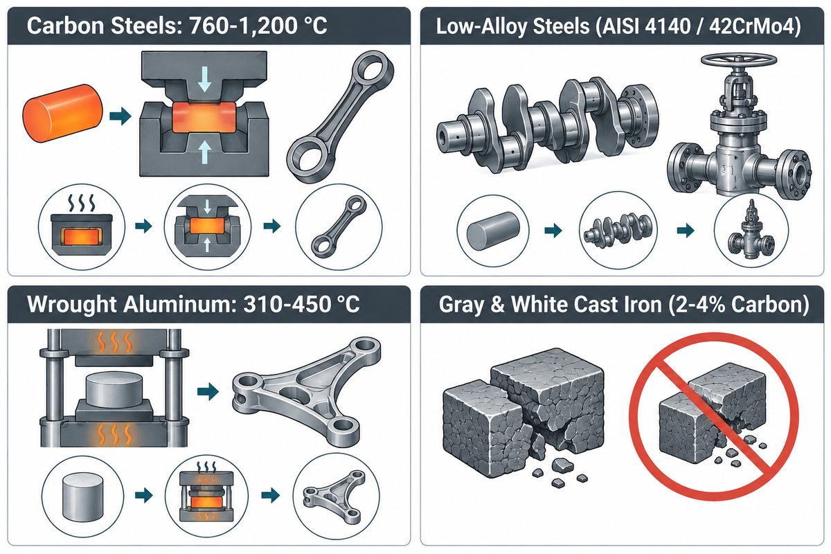
Wrought carbon steels, stainless steels, nickel and other superalloys, titanium, aluminum and copper/brass, and low-alloy steels, all forge reliably in closed dies. Success is determined by the balance of press tonnage and die preheat and alloy hot flow stress. Forging difficulty increases as the flow stress increases and the workable temperature band decreases. For more information, please see The Open University Manupedia.
| Alloy Family & Typical Grades | Closed-Die Suitability | Reference Hot Forging Band | Key Process & Procurement Note |
|---|---|---|---|
| Carbon Steels (AISI 1018–1045, ASTM A105) | Recommended (Easy) | 760–1,200 °C (Open University) | Broad thermal window; lowest die wear; ASTM A105 capped at 10,000 lb (4,540 kg) per piece |
| Low-Alloy Steels (AISI 4140 / 42CrMo4, 4340, 8620) | Recommended (Moderate) | 760–1,200 °C reference band (Open University; heating and finish limits vary by grade) | 42CrMo4 (EN 10083 / DIN 1.7225) functionally matches AISI 4140; confirm exact certification standard |
| Austenitic & PH Stainless (304, 316, 17-4PH) | Suitable (Moderate-High Load) | 930–1,180 °C (Open University) | Higher forging loads and slower thermal conductivity than carbon steel; avoid carbide sensitization |
| Duplex Stainless (F51 / UNS S31803) | Suitable (Strict Control) | Narrow hot window within stainless band | Requires solution annealing and rapid quench to maintain ferrite-austenite phase balance |
| Wrought Aluminum (6061, 7075, 2014) | Recommended (Preheated Dies) | 310–450 °C (Open University) | High thermal conductivity chills billets rapidly; hydraulic presses with preheated dies preferred |
| Copper & Forging Brass (C37700, C11000) | Recommended (Easy) | 460–1,000 °C (Open University) | High ductility and clean cavity fill for valves, fittings, and electrical connectors |
| Titanium Alloys (Ti-6Al-4V) | Suitable (Specialist) | 825–900 °C (Open University; below beta-transus) | High flow stress; strain-rate sensitive; aerospace structural hardware |
| Nickel Superalloys (Inconel 718, 625) | Suitable (High Wear) | 750–1,125 °C (Open University) | High die stress and accelerated cavity wear; oilfield sour-service and turbine hardware |
| Gray & White Cast Iron (2–4% Carbon) | Not Recommended (Fails) | Not applicable | Excess carbon above ~2.1% forms brittle graphite or carbide that cracks under impact (ManufacturingBase); use forged 1045/4140 steel or cast iron casting |
| Free-Machining Steels & Cast Al (12L14, A356, A380) | Poor Conventional Fit | Avoid standard hot impression dies | Sulfide inclusions or lead promote hot splitting/shortness; high-Si cast Al has low solid-state forgeability; substitute 1018/4140 or wrought 6061/7075 |
Which Metals Are Not Ideal for Closed-Die Forging?
Gray and white cast iron are the primary metals not suitable for closed-die forging. Per ManufacturingBase, cast iron contains 2-4% carbon, well above the roughly 2.1% solubility limit. Excess carbon forms free graphite flakes or hard iron carbide, which crack and crumble instead of flowing plastically. Three other industrial material groups are poor fits for conventional impression dies:
- Free-machining resulfurized and leaded steels (e.g. 12L14 or resulfurized grades) are poor primary candidates for structural closed-die forging. Manganese-sulfide stringers decrease transverse ductility and promote splits during severe deformation; added lead, melting at forging temperature, causes hot shortness. Use standard 1018, 1045, or 4140 steel as a substitute unless a grade is specifically qualified.
- High-silicon cast aluminum alloys (e.g. A356 and A380) depend on eutectic silicon networks for molten mold fill and exhibit lower solid-state forgeability than wrought aluminum. While specialized cast-forging hybrid processes exist for A356, buyers seeking conventional closed-die aluminum forgings should specify wrought 6061 or 7075 stock.
- Refractory and specialty metals (e.g. tungsten and beryllium) and non-metallic cemented carbides are outside the scope of routine commercial steel and aluminum forge processes. Plastic forming of tungsten and beryllium is possible under controlled conditions with additional exposure controls for beryllium; powder processing and sintering are common ways to shape carbide materials.
Cross-border buyers should name both the alloy grade and its governing standard. As Augmino explains, European 42CrMo4 (EN 10083 / DIN 1.7225) matches AISI/SAE 4140 and JIS SCM440 for most applications. Buyers must still confirm which exact standard appears on the supplier’s mill test certificate.
Alloy Steel vs. Aluminum Closed-Die Forging: Temperatures and EN 10243-1 / ASTM Tolerances
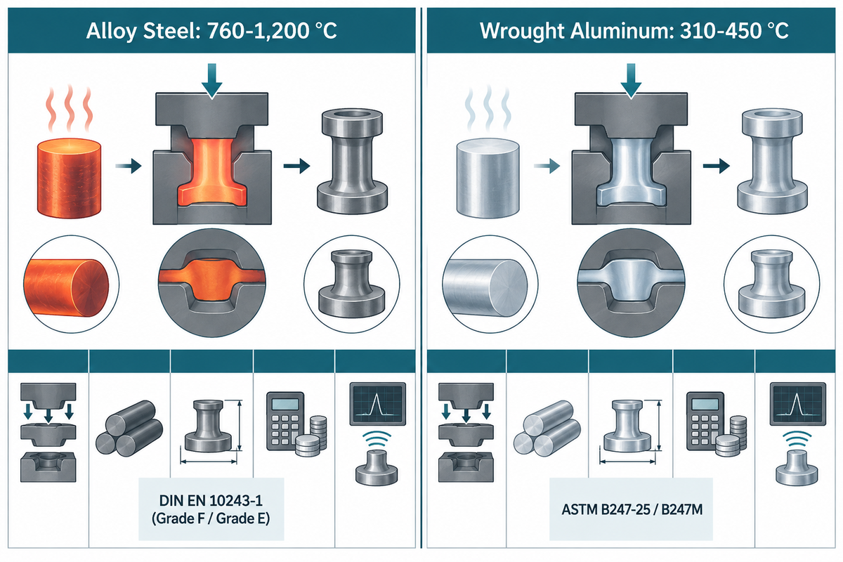
The Open University Manupedia lists a broad hot-forging band of 760–1,200 °C for carbon and alloy steels, with billet-heating and finish-forging limits set by alloy grade. Wrought aluminum alloys forge cooler at 310–450 °C (Open University). EN 10243-1 sets dimensional tolerances for applicable steel forgings, whereas ASTM B247-25 / B247M governs aluminum mechanical acceptance by listed alloy, temper, and maximum section thickness.
Placing a generic “±0.5 mm all over” block on a forging print creates quote conflict. Forged tolerances vary by direction. Length and width vary with wear and thermal contraction of the billet. Thickness varies with the closure of the forge dies and misalignment. Calling out the exact standard prevents surprise CNC fixture rework.
| Parameter | Alloy Steel (e.g., 4140 / 42CrMo4, 4340) | Wrought Aluminum (e.g., 6061, 7075) |
|---|---|---|
| Hot Forging Temperature Band | 760–1,200 °C reference band (Open University; exact billet-heating and finish-forging limits set by grade) | 310–450 °C (Open University; exact ceiling depends on alloy grade) |
| Thermal Window Sensitivity | Broader workable thermal band before reheating is required | Narrow; overheating risks incipient melting, underheating causes cracking |
| Die Preheating Strategy | Moderate preheat to prevent thermal shock while limiting die softening | Preheated dies to reduce rapid heat extraction and surface chilling (near-billet die heating belongs to specialized isothermal/hot-die forging) |
| Dimensional & Product Standards | DIN EN 10243-1 (Grade F normal / Grade E close dimensional tolerances); ASTM A521 (closed-die steel product requirements) | ASTM B247-25 (inch-pound) / B247M (metric) aluminum forging product requirements; FIA aluminum tolerance guidelines |
| Published Scope Limits | EN 10243-1 covers hot drop and vertical-press forgings ≤250 kg mass and ≤2,500 mm max dimension (excludes horizontal upset) | ASTM B247-25 defines mechanical acceptance by listed alloy, temper, and max section thickness |
| Typical As-Forged Accuracy | +1.5/−0.5 mm (0.5–1 kg hot steel flash); +0.3–0.4 mm (Hatebur-type flashless hot former) (Open University) | Often tighter near-net profiles when run on preheated-die hydraulic precision presses (confirm dimensional table per buyer drawing) |
| Oxidation & Surface Scale | Heavy iron-oxide scale at high forging heat; heated by induction or furnace and cleaned via shot blasting, hydraulic descaling, or pickling | No heavy iron scale; graphite lubrication residue cleaned chemically or mechanically |
| Machined Finish Tolerance | Post-forge CNC machining to ISO 286-1 IT grades (IT01–IT18 scale per UTEC Industrial) on mating bores and shafts | Light CNC finishing to ISO 286-1 IT grades on mating faces and precision bores |
| Preferred Press Type | Crank mechanical press, screw press, or drop hammer | Hydraulic press (750–65,000 tons per Open University) or precision screw press |
Under EN 10243-1, Forging Grade F covers normal dimensional accuracy on standard production equipment, while Forging Grade E provides closer limits. Closer dimensions than Grade E require buyer-supplier agreement, verified precision-forging or coining capability, or finish CNC machining to ISO 286-1 International Tolerance (IT) grades (IT01, IT18 scale) where specified. EN 10243-1 applies strictly to hot drop and vertical press carbon or alloy steel forgings up to 250 kg and 2,500 mm maximum dimension, excluding horizontal upset forgings.
Temperature alone does not guarantee mechanical properties for aluminum forgings. ASTM B247-25 (and metric B247M) defines mechanical acceptance by listed alloy, temper (such as T6 or T73), and maximum section thickness. It does not serve as a universal dimensional tolerance table. On thin-ribbed 6061 aerospace brackets, cold dies chill outer ribs rapidly against steel tooling and cause tearing or underfill. Switching to continuously preheated dies on a hydraulic press stabilizes metal flow. Lock alloy grade, tolerance class, and section thickness through a material grade and standard review prior to tooling release.
Closed-Die Forging Equipment: Mechanical, Hydraulic, and Screw Presses vs. Drop Hammers
Forging equipment adjusts strain rate, fill, repeatability, and cycle time. Mechanical crank and friction screw presses cover 500-14,000 tons (The Open University Manupedia). Hydraulic presses designed for aluminum alloy forgings cover 750-65,000 tons, while drop forging hammers are used for deep cavity steel parts.
| Equipment Class | Force & Energy Delivery | Typical Load / Output | Best-Fit Alloys & Parts |
|---|---|---|---|
| Drop Hammer (Gravity / Power) | Energy-limited; repeated high-velocity impact blows | Flexible batch rates; lower capital cost per blow energy | Deep-cavity carbon and alloy steel forgings; lower-to-medium runs |
| Mechanical Crank Press | Stroke-limited; single fixed-stroke squeeze per impression | 500–14,000 tons; automated lines 300–600 parts/h (Open University) | High-volume steel gears, hubs, connecting rods with tight thickness repeatability |
| Hydraulic Forging Press | Load-limited; slow, constant-speed controlled squeeze | 750–65,000 tons for aluminum (Open University); ultra-heavy 60,000-ton aerospace units (Forging Magazine) | Strain-rate-sensitive aluminum, titanium, magnesium, and large structural forgings |
| Friction / Electric Screw Press | Energy-limited with precision ram guides; programmable blow energy | 500–14,000 tons (Open University); high vertical accuracy | Precision forging of turbine blades, brass/steel valves, and thin-wall parts |
| Automatic Multi-Station Hot Former | Horizontal high-speed progressive enclosed-die stations (e.g., Hatebur) | 4,000–10,000 parts/h flashless (Open University) | High-volume axisymmetric rings, bearing races, nuts, and gear blanks |
Forging requires matching press tonnage to projected plan area (including flash land), alloy flow stress, and cavity depth. Sending strain-rate-sensitive 7075 aluminum or Ti-6Al-4V to a fast impact hammer risks shear cracking. Conversely, running a high-volume 4140 union nut on a slow hydraulic press cuts output speed and increases die contact wear. Verify each supplier’s press tonnage, ejector set up, and in-house forging capabilities before awarding dies.
Closed-Die Forging Die Costs, Break-Even Volume, and Unit Economics
Vendor benchmarks place custom closed-die steel tooling at $5,000–$50,000+ (WALKSON). MFG SOLUTION lists $5,000–$15,000 for simple single-cavity dies and $50,000–$80,000 for complex multi-cavity dies, while China Metal Supply notes $3,000–$500,000+ across industrial sizes. Reference 2026 forging prices run $1.5–$5/kg for carbon steel and $5–$15/kg for alloy steel (Weforging), with finishing adding $0.50–$5 per part (WALKSON).
Public vendor tables rarely clarify whether the denominator is gross weight (including flash and trim), or finished weight. They also differ in how they treat heat treatment, NDT and die amortization.
The 4-Factor Closed-Die Break-Even Formula (Worked Example)
Published break-even volumes vary with part complexity and machining savings. China Metal Supply notes the closed-die process pays off from roughly 100–500 pieces per year. MFG SOLUTION cites 500–1,000 pieces per production run, and MTS Forge cites NIST data showing aluminum alloy break-even near 50 pieces. As Longrui Forging explains, exact break-even equals die cost divided by per-piece savings. Account for four drivers: complete tooling NRE, gross billet weight with flash loss, forging plus heat treatment and finish CNC, and cavity re-sinking over long runs. A 2024 peer-reviewed Materials review notes that reduced die life can raise total production costs by up to 40%.
Use the 4-Factor Closed-Die Break-Even Formula on matched quotes on the same drawing:
Break-Even Quantity (parts) = Complete Tooling NRE ÷ (Alternative Finished Unit Cost − Closed-Die Finished Unit Cost)
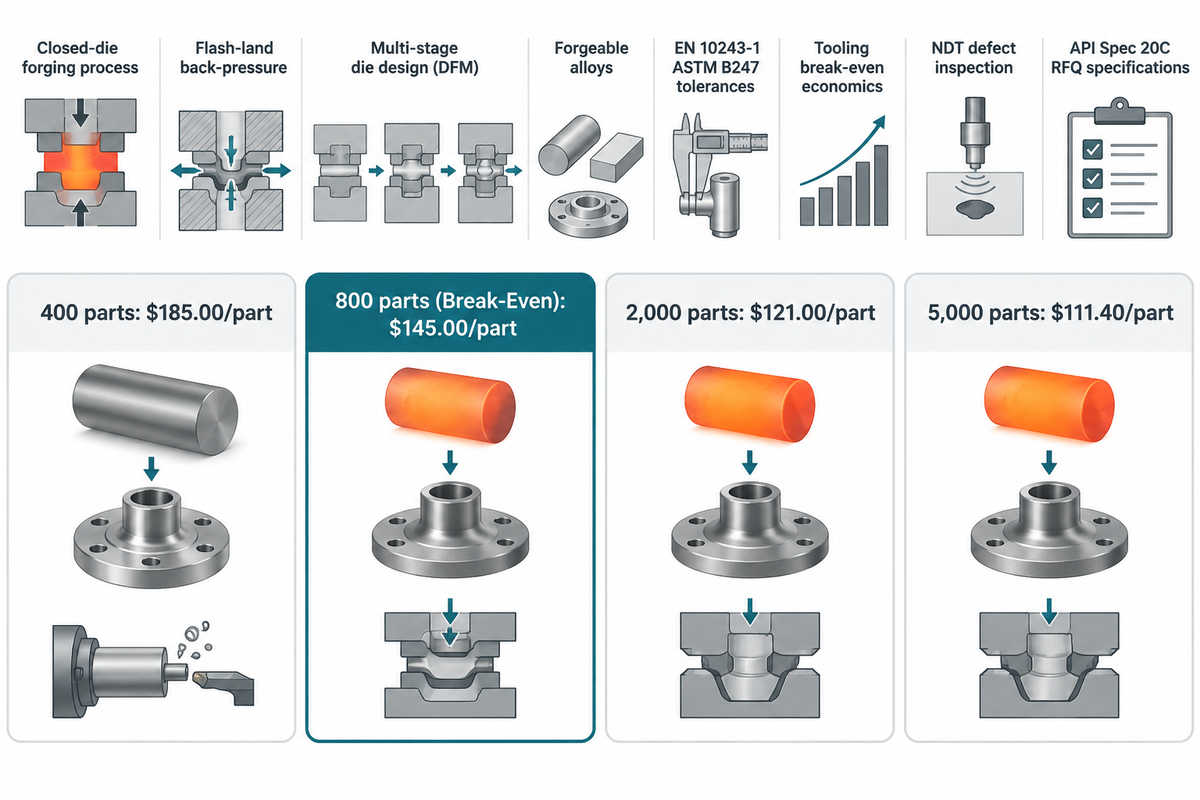
Illustrative Engineering Scenario (formula demonstration only, not a live quote): Consider a 12 kg finished AISI 4140 contoured flange hub. Assume CNC machining from a 26 kg rolled bar quotes at $145 per finished part. Assume a closed-die shop quotes $32,000 for complete blocker, finisher, and trim dies within published $5,000–$80,000 benchmarks. Typical tooling lead times run 4–8+ weeks (China Metal Supply) or 8–14 weeks including the first production run (MFG SOLUTION). The same quote prices each finished closed-die part at $105, covering 15 kg gross billet weight, forging, quench-and-temper heat treatment, and finish CNC on mating bores. Net unit savings equal $145 − $105 = $40 per part.
| Cumulative Program Volume | Amortized Die Cost / Part | Closed-Die Total Cost / Part | Bar-Machined Cost / Part | Economic Verdict |
|---|---|---|---|---|
| 400 parts | $80.00 | $185.00 | $145.00 | Bar machining wins by $40/part |
| 800 parts (Break-Even) | $40.00 | $145.00 | $145.00 | Cost parity ($32,000 ÷ $40 = 800 parts) |
| 2,000 parts | $16.00 | $121.00 | $145.00 | Closed-die saves $24/part ($48,000 net) |
| 5,000 parts | $6.40 | $111.40 | $145.00 | Closed-die saves $33.60/part ($168,000 net) |
Confirm three tooling terms in writing before releasing a purchase order. First, verify that the NRE covers blocker, finisher and trim dies as well as first article samples. Second, define buyer die ownership and dimensional triggers for cavity re-sinking. While The Open University Manupedia states that typical hot steel die life is 10,000–15,000 parts at 1,000–1,150 °C, actual re-sinking depends on alloy, wear rate, and dimensional inspections rather than a universal shot count. Third, define terms for storage of inactive dies.
Common Closed-Die Forging Defects, Heat Treatment, and NDT Inspection
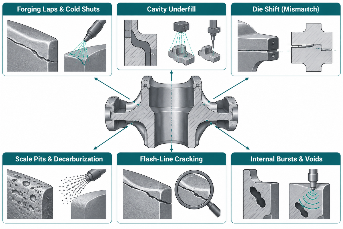
Defects in closed die forging include laps (folds), cold shuts, die shift (mismatch), cavity underfills, scale pits, flash-line cracks, and internal bursts. Welding overlay can’t remedy defects such as unbonded folds and laps. Whether a given defect can be excavated and a qualified weld made in its place depends on the requirements in the relevant product specification, as well as customer approval. Purchase orders should therefore pair each defect class with an appropriate inspection method.
A forging lap occurs when two hot metal surfaces fold against each other without fusing (Transvalor). Oxidation can make laps visible. Nondestructive evaluation methods that use magnetism may be coupled with target flaw depth to detect laps. Defining an acceptance limit can assist the determination of a good part.
| Defect Mode | Primary Root Cause | Process Prevention Control | Required Inspection / NDT Method |
|---|---|---|---|
| Forging Laps & Cold Shuts | Improper preform mass distribution, sharp die radii, or metal folding back onto itself | FEM point-tracking simulation before die sinking; generous blocker radii | Magnetic Particle Testing (MT, ASTM E709 test practice) on ferromagnetic alloys (including magnetic stainless); Liquid Penetrant (PT) for surface-breaking flaws on non-magnetic alloys (Al, Ti, austenitic stainless); apply specification acceptance and weld-repair rules |
| Cavity Underfill | Undersized billet, low billet/die temperature, insufficient flash back-pressure | Verify billet weight control, flash-land geometry, and induction pyrometry | 3D laser scan / CMM first-article inspection and go/no-go profile gauges |
| Die Shift (Mismatch) | Lateral thrust on stepped parting line or worn press ram gibs | Use flat parting plane, mechanical die counterlocks, and guide-pin checks | CMM parting-line offset check against EN 10243-1 Grade F/E mismatch limits |
| Scale Pits & Decarburization | Excessive furnace soak time or unremoved oxide scale pressed into surface | Fast induction heating, pressurized water/mechanical descaling before first blow | Surface visual check after shot blasting; metallographic decarb depth test |
| Flash-Line Cracking | Excessively thin flash land cooling too fast or dull trimming dies tearing parting edge | Tune flash thickness ratio; trim hot before alloy cools into brittle zone | MT or PT focused specifically along trimmed parting line |
| Internal Bursts & Voids | Secondary tensile stresses at centerline from improper reduction or overheating | Control billet soaking uniformity and press strain rate | Ultrasonic testing of steel forgings under ASTM A388 (applicable UT standards for Al/Ti); coverage of critical sections limited by geometry and probe access |
Heat Treatment, EN 10204 3.1 Traceability, and the ASTM E8 vs. ISO 6892-1 MTC Trap
Forging refines grain flow, while heat treatment establishes final strength, toughness, and hardness through normalizing, quenching and tempering (Q&T), or solution annealing. Buyers verify those properties with heat-traceable EN 10204 Type 3.1 (or EN 10204-3.1B on Welong shipments) mill test certificates. Crucially, ASTM E8 uses a 4D tensile gauge length whereas ISO 6892-1 uses 5.65√S0 (roughly 5D), creating an MTC elongation mismatch trap when certificates cross standards.
That cross-border tensile mismatch catches many quality teams. ISO 6892-1:2019 runs at 10–35 °C (or 23 ± 5 °C controlled) and covers both proportional and non-proportional specimens. For round proportional specimens, gauge length is L0 = 5.65√S0 (approximately 5D, minimum 15 mm). By contrast, ASTM E8/E8M-24 uses a 4D gauge length for inch-pound E8 round specimens and 5D for metric E8M specimens. As Biopdi explains, elongation values from ASTM E8 (4D) and ISO 6892-1 (5.65√S0) cannot be compared numerically without matching the governing standard. ASTM E8/E8M-24 also warns that local test coupons may not represent whole-part service behavior, so define prolongation or sacrificial coupon locations on the print.
Oilfield and Heavy Industrial Applications, Certifications, and Supplier Selection
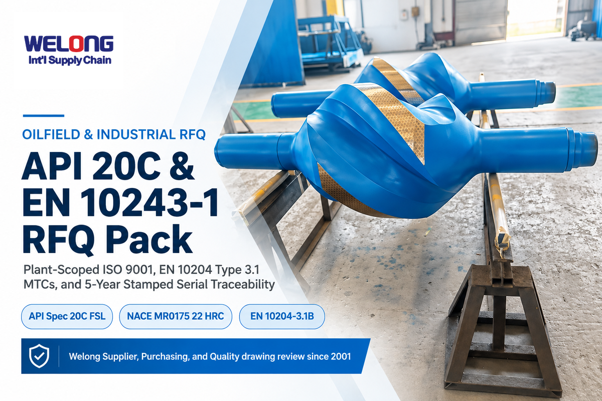
Heavy industrial and oilfield buyers acquire closed-die steel forgings for various applications, such as valve bodies, bonnets, hammer unions, wing nuts, swivel joints, tees, lifting hooks, and gears. Petroleum and natural gas pressure suppliers should hold plant-scoped ISO 9001:2015 certification. They must also meet API Spec 20C at the Forging Specification Level designated for the purchased product (chosen from four FSLs).
“This specification establishes requirements for four different FSLs. These FSL designations define different levels of forged product technical, quality, and qualification requirements.”
For sour-service oilfield parts, general Part 2 provisions of NACE MR0175 / ISO 15156 cap carbon and low-alloy steel hardness at 22 HRC (250 HV10) across parent metal, weld metal, and heat-affected zones (Kasko Makine). Compliance also requires qualified heat treatment and material condition, subject to standard-specific exceptions, with actual hardness values reported on EN 10204 Type 3.1 or 3.2 MTCs. Buyers source custom closed-die steel forgings through drawing-led supply-chain partners such as Welong, whose shipments include EN 10204-3.1B certificates, UT/MT reports, and five-year stamped serial traceability. Direct forge plants include Canton Drop Forge (hammers up to 50,000 lb) and Cromdane Steel (ISO 9001:2015 QMS with API 6A 21st Edition validation). Other specialized plants include Longrui Forging (5–520 kg parts on 2,000–6,000 T presses) and MTS Forge (up to 1,500 lb for aerospace, defense, power generation, and nuclear service). Always audit active plant-level certificates against your specific drawing.
When cyclic torque or shock pressure is a concern, closed-die forgings outperform sand castings.
- Oil and gas wellhead hardware like hammer unions (Fig. 602, 1002, 1502), compact valve bodies, swivel elbows, BOP parts, and downhole connectors uses AISI 4140, 4130, and ASTM A105. ASTM A105 limits individual forgings to 10,000 lb (4,540 kg), while ASTM A266/A266M covers carbon-steel pressure vessel forgings, including heavier pieces within that scope (Aienginear).
- Hot formers and crank presses are used in the automotive and rail industries to produce connecting rods, steering knuckles, and axle spindles.
- Aerospace and defense structures form wrought aluminum (7075, 2014) and titanium (Ti-6Al-4V) landing-gear fittings and wing ribs on preheated-die hydraulic presses.
The API 20C / EN 10243-1 RFQ Specification Pack (8-Point Buyer Checklist)
A corporate ISO 9001 certificate does not prove plant-level API Spec 20C or API 6A capability. Lock these eight items in your API 20C / EN 10243-1 RFQ Specification Pack before soliciting quotes:
- Provide dual drawings (3D STEP plus 2D forging and finished prints) separating the as-forged draft and parting-line envelope from final CNC datums and surface-finish requirements.
- Name the exact alloy grade and governing standard (such as AISI 4140 per ASTM A521 or 42CrMo4 per EN 10083) and any approved equivalents (Liju Engineering).
- Name the EN 10243-1 Grade F or Grade E dimensional tolerances for applicable steel forgings, or ASTM B247-25 alloy, temper and thickness requirements for aluminum forgings. Provide mismatch and die-closure limits.
- Define the heat-treatment cycle, tensile test standard (ASTM E8, E8M, or ISO 6892-1), and coupon location. For sour service, specify applicable NACE MR0175 / ISO 15156 Part 2 requirements covering environment, material condition, heat treatment, standard exceptions, and the general 22 HRC (250 HV10) limit.
- Pair surface NDT (ferromagnetic MT under ASTM E709 or surface-breaking PT) with steel UT (ASTM A388) and governing acceptance and weld-repair criteria.
- Verify active plant-scoped ISO 9001:2015 certification, the designated API Spec 20C FSL tier for applicable oilfield pressure parts, and API 6A validation where wellhead service requires it.
- Require a First-Article Inspection (FAI) gate combining a CMM dimensional report, macro-etch grain-flow check on critical parts, and EN 10204 Type 3.1 MTC review prior to batch release.
- Document Commercial tooling terms including die ownership, dimensional cavity re-sinking triggers, and an annual forecast band. Include five-year stamped serial and heat-number traceability consistent with Welong’s industrial forging shipments.
Shaanxi Welong Int’l Supply Chain Mgt Co., Ltd (Welong) has been coordinating drawing-led industrial forgings since 2001. Instead of forcing every drawing onto one press, Welong’s Supplier, Purchasing, and Quality roles review each part prior to PO release. Depending on the drawing, selected production could be closed-die or open-die forging, rolled rings, or forged bars. Welong then coordinates pre-vetted forge shops with documented heat treatment, UT/MT inspection, EN 10204-3.1B documentation, and five-year piece-level traceability. Study Welong’s drawing-led industrial forgings case study, or prepare your case file using the drawing-led forging RFQ case study guide.
Closed-Die Forging Automation, FEM Die Simulation, and Near-Net Energy Drivers
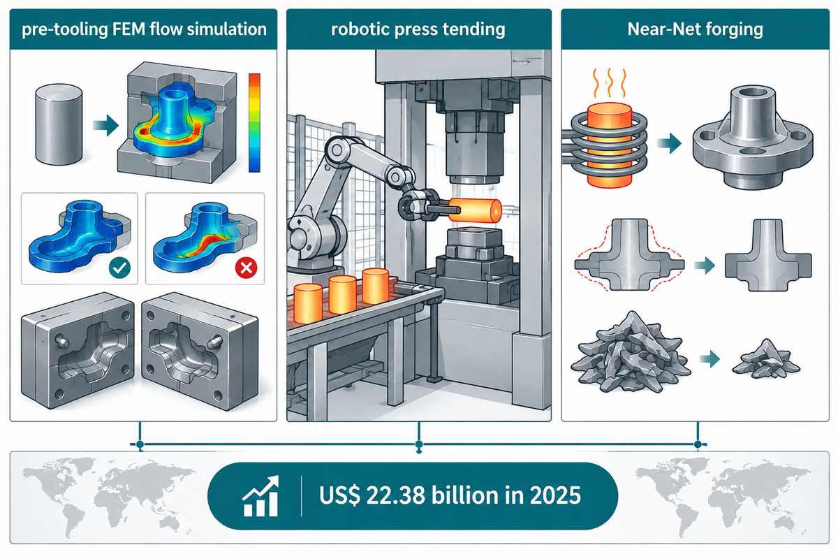
Skilled operator shortages, carbon border adjustment, and tighter launch windows are prompting three upgrades in closed-die forging shops. Newer shop facilities use pre-tooling FEM flow simulation, robotic press tending and Near-Net forging, reducing energy consumption and raw material loss.
Leading shops no longer wait for physical die trials to discover folds or underfill. Engineers simulate billet heating, cavity fill, contact pressure, and thermal fatigue before machining H13 blocks. Numerical simulation reviews (MDPI Applied Sciences, 2026) and defect workflows (Transvalor) show how automated point-tracking and contact-scalar checks detect laps digitally. Catching defects in software avoids weeks of physical die rework.
Peer-reviewed studies comparing manual and robotic hot die forging (Springer, 2026; ScienceDirect, 2025/2026) show how robotic transfer stabilizes cycle timing and die contact. This enhances consistency in forging process and narrows billet temperature scatter, thus slowing thermal fatigue cracking. Market growth reinforces these upgrades. According to GlobeNewswire / Research and Markets (Oct 6, 2026) and The Insight Partners, the global closed-die forging market reached US$ 22.38 billion in 2025. Forecasts project US$ 42.94 billion by 2040 (4.44% CAGR, 2026–2040) on EV, aerospace, and automated demand. For EU imports, mandatory Carbon Border Adjustment Mechanism (CBAM) obligations took effect January 1, 2026 for importers exceeding 50 metric tons/year (ULMA Forge). Induction heating efficiency and lower material waste now affect landed cost directly.
Frequently Asked Questions About Closed-Die Forging
What is the main difference between open-die and closed-die forging?
Open-die forging compresses heated metal between flat or simple dies without enclosing the workpiece, while closed-die forging forces the billet into custom shaped cavities.
That type of setup works well for large parts such as shafts, rings, and low-quantity blocks. Closed-die tooling reproduces complex geometry with tighter dimensional accuracy, lower finish machining stock, and higher upfront die tooling cost suited to recurring batches.
Is it possible to use closed-die forging for aluminum alloys?
Wrought aluminum alloys such as 6061, 7075 and 2014 are widely closed-die forged at 310–450 °C for aerospace and structural hardware.
Because aluminum loses heat rapidly against steel tooling, shops typically use preheated dies on controlled equipment—such as hydraulic or screw presses—suited to its narrow temperature window. High-silicon casting grades like A356 and A380 have low solid-state forgeability in standard impression dies.
What forging temperatures are used for steel versus aluminum in closed dies?
As per The Open University Manupedia, carbon and alloy steels forge between 760 and 1,200 °C, while wrought aluminum runs between 310 and 450 °C.
Steel offers a wider range of workable temperatures with grade-specific heats, but builds heavy iron scale. Aluminum requires preheated dies to limit surface chilling and strict upper temperature control to prevent incipient melting.
Is closed-die forging the same as impression-die forging?
In commercial purchasing, both terms commonly refer to forging in two-part cavity dies, with peripheral flash in conventional impression-die forging and no flash in flashless closed-die forging.
Technical handbooks distinguish true closed-die forging (flashless) from impression-die forging (with flash) using fully enclosed volume-controlled cavities.
How much do closed-die forging dies cost and what annual quantity breaks even?
Custom steel dies run $5,000–$50,000+ (WALKSON) and $5,000–$80,000 (MFG SOLUTION), with break-even near 100–500 pieces/year (China Metal Supply) or 500–1,000 pieces/run (MFG SOLUTION).
Exact payback is the total tooling NRE divided by the net savings per part compared to open-die or CNC bar-machining after accounting for flash scrap and finish machining. Aluminum alloy runs can break even at around 50 pieces (MTS Forge), while simpler low-machining parts need larger volumes. Break-even volumes for simpler, lower-machining parts, are higher.
Which metals cannot be forged in closed dies?
Gray and white cast iron cannot be forged because 2–4% carbon creates brittle graphite flakes or iron carbide (ManufacturingBase).
Free-machining steels, casting aluminum (A356, A380), and tungsten or beryllium do have specialized hot-working routes, but buyers avoid them for standard commercial impression-die runs.
What inspection tests and certifications should buyers require on closed-die steel forgings?
Specify plant-scoped ISO 9001:2015 and EN 10204 Type 3.1 heat-traceable mill test certificates. Pair Magnetic Particle Testing (ASTM E709) on ferromagnetic surfaces with Ultrasonic Testing (ASTM A388) on steel forgings.
For petroleum and natural gas pressure components, specify the applicable API Spec 20C Forging Specification Level (chosen from four FSLs) and API 6A validation where required. For sour-service environments, verify full NACE MR0175 / ISO 15156 Part 2 compliance covering service environment, material condition, heat treatment, standard exceptions, and the general 22 HRC maximum hardness.
Next Step: Validate Your Drawing Before Releasing Die Tooling
Reliable closed-die sourcing begins before cutting tool steel. Verify closed-die forging economics against open-die forging or CNC machining first. Clear your print through the Closed-Die DFM Geometry Gate referencing EN 10243-1 for steel or ASTM B247 for aluminum where applicable. Lock plant-level ISO 9001, NDT acceptance criteria, and applicable API Spec 20C tiers for oilfield pressure parts. Share your CAD model, alloy grade, and annual volume forecast through Welong’s custom industrial forgings portal for a pre-PO route and specification review.
Reviewed by the Shaanxi Welong Int’l Supply Chain Mgt Co., Ltd technical team.
References & Sources
- The Open University, OpenLearn Manupedia Hot Forging (Closed Die): Manufacture, Materials, and Design
- NIH PubMed Central (Materials, 2024) Durability of Forging Tools Used in the Hot Closed Die Forging Process
- American Petroleum Institute (via GlobalSpec) API Spec 20C: Closed Die Forgings for Use in the Petroleum and Natural Gas Industry
- European Committee for Standardization (via GlobalSpec) EN 10243-1: Steel Die Forgings, Tolerances on Dimensions
- ASTM International – ASTM B247-25: Standard Specification for Aluminum and Aluminum-Alloy Die Forgings
- ASTM International – ASTM E8/E8M-24: Standard Test Methods for Tension Testing of Metallic Materials
- The Forging Industry Association (FIA) – Case Study No. 10: Flashless Forged Connecting Rod
- CarboForge Glossary of Forging Terms (Die Impressions & Trimming Tooling)
- ManufacturingBase Can Cast Iron Be Forged? Gray, Ductile and A48 Reality
- Haoyuan Special Steel – H13 vs. DIN 1.2344 vs. JIS SKD61 Hot-Work Tool Steel Equivalence
- Kasko Makine NACE MR0175 / ISO 15156: Sour Service Materials Explained
- China Metal Supply – Open-Die vs. Closed-Die Forging: Tooling Cost, Lead Time, and Volume Calculation
- Longrui Forging Closed Die or Open Die Forging: Tooling Economics & Selection Guide
- MTS Forge Closed-Die Forging vs. Open-Die Forging: Complete Guide
- Applied Sciences (MDPI, 2026) Numerical Simulation of Die Forging Processes: A Review of Finite Element Methods
- Performance Evaluation of Manual and Robotised Hot Die Forging (Springer, 2026)
- Gear Solutions Magazine Failure Analysis of H13 Gear Blank Forging Dies
- How to Avoid Closed Die Forging Defects Using Numerical Simulation (Transvalor, 2026)
- Trenton Forging Impression Die Versus Flashless Forging
- Biopdi ASTM E8 vs. ISO 6892-1 Tensile Testing of Metals
- GlobeNewswire / Research and Markets (Oct 6, 2026) Closed Die Forging Market Size, Share, Trends, and Forecast 2026–2040
- ULMA Forge EU CBAM Mandatory Requirements for Imported Iron and Steel Forgings (2026)