Get in touch with Welong Company

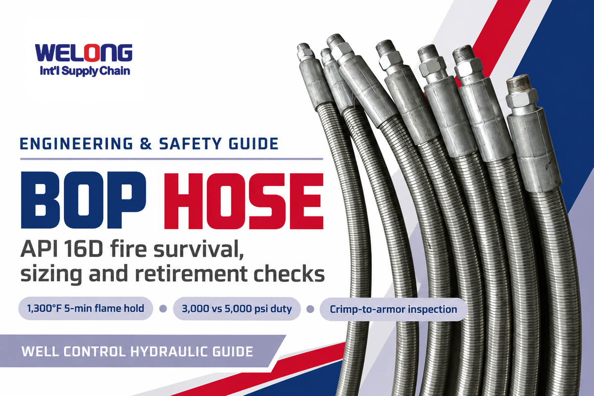
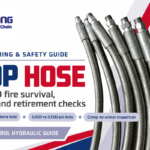
A BOP Hose carries high-pressure hydraulic fluid from the rig’s accumulator control unit to the blowout preventer stack during drilling and well-servicing operations. Unlike circulation lines that pump mud downhole, these flexible control lines transmit the hydraulic energy needed to close annular and ram preventers within seconds when a kick threatens the wellbore.
This engineering guide covers API Spec 16D fire-qualification testing, multi-layer thermal barriers, 3,000 psi versus 5,000 psi working pressure selection, bore-flow sizing, and field retirement checks across the oil and gas industry. For assembly orders, catalog tables, and quotations, go to the BOP control hose solution page.
Updated November 2026 · By Karry
Quick Engineering Summary
An oilfield BOP hose is a fire-resistant hydraulic control assembly linking the accumulator manifold to the blowout preventer stack. Under API Spec 16D Section 10.1.2.1, Division 1 surface control lines must contain rated working pressure in a 1,300°F (700°C) flame for 5 minutes. Sizing requires matching the circuit’s 3,000 psi or 5,000 psi maximum pressure and choosing a bore that meets API Standard 53 closing-time limits.
Key Engineering Takeaways
- API Spec 16D governs hydraulic control lines to the stack, whereas API Spec 16C governs wellbore choke and kill lines and rigid steel piping covers fixed manifold runs.
- A laboratory 1,300°F (700°C) 5-minute flame test evaluates pressurized control fluid; extended hydrocarbon fires require dedicated thermal barriers and shielded routing.
- Doubling hose inside diameter from 0.5 inch to 1.0 inch increases cross-sectional flow area fourfold and cuts fluid velocity to one-quarter at equal gallon-per-minute demand.
- BOP stack pressure tests verify test-day containment under 30 CFR 250.737 or API Standard 53, so visual depressurized inspection remains necessary to catch cover or ferrule damage.
What a BOP Hose Does in Well Control Hydraulic Systems
On a land or offshore drilling rig, the hydraulic control manifold (usually referred to as the Koomey or accumulator unit) stores pressurized hydraulic fluid in nitrogen-precharged bottles. When a control valve is actuated by a driller or toolpusher, the fluid travels through a rigid steel manifold and flexible control lines to the wellhead stack to open or close ram and annular preventers.
What is a BOP hose used for on a drilling rig?
During drilling operations, the BOP hose transports pressurized hydraulic control fluid, such as 3,000 psi or 5,000 psi water-glycol or mineral hydraulic oil, from the remote accumulator unit to the blowout preventer stack. Because the flexible line bridges a stationary manifold and a vibrating wellhead stack or walking-rig substructure, it allows for relative movement where rigid steel piping cannot flex while helping protect the control circuit against rig-floor abrasion, crush loads, and flash fires when built as a fire-qualified assembly.
As clarified by the Railroad Commission of Texas Rule 13 well-control review, API Standard 53 Section 6.3.11.2.5 states that all rigid or flexible lines between the control system and the BOP stack must meet the fire-test requirements of API Spec 16D, including end connections, and carry a rated working pressure equal to the rated working pressure of the BOP control system. Rigid steel piping is used in the fixed substructure runs, and in areas where fire testing isn’t performed on the rigid pipe. While many rigs use rigid steel piping along fixed substructure runs where fire testing is not generally performed on the rigid pipe itself, flexible control hoses form the final articulated connection to the surface-mounted stack in Division 1 hazardous areas and must be fire-tested to contain rated working pressure at 1,300°F (700°C) for 5 minutes.
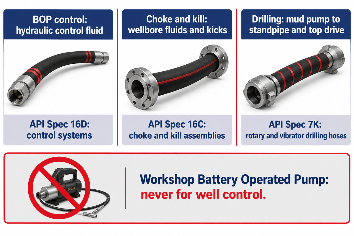
When evaluating oilfield hose families, there are typically three distinct products associated with rig equipment. First, API Spec 16D, in the scope of the API Subcommittee 16 series of standards, covers control systems and diverter systems. Second, choke and kill hose assemblies fall under API Spec 16C and carry high-pressure wellbore fluids, gas kicks, and kill mud during well-control circulation rather than hydraulic actuator oil. Third, rotary and vibrator drilling hoses fall under API Spec 7K to pump drilling mud between the mud pump, standpipe, and top drive.
Outside the petroleum sector, industrial lubrication catalogs also use the acronym “BOP” for workshop Battery Operated Pump grease and oil dispenser hoses. Those low-pressure workshop transfer lines have zero connection to oilfield well control and must never appear on a rig bill of materials.
API Spec 16D and Lloyd’s Register Fire-Test Verification
During a well-control emergency, a gas kick or surface release can ignite before every ram on the stack has cycled closed. If an unqualified hydraulic hose burns through during a rig-floor fire, the open line vents accumulator pressure to the atmosphere, and can interrupt or prevent blowout preventer actuation.
What fire test must an API 16D BOP hose pass?
As summarized in US Patent Application US20120186684A1 and the Railroad Commission of Texas Rule 13 well-control review, according to API Spec 16D Section 10.1.2.1, flexible control lines serving a surface-mounted blowout preventer stack or diverter in a Division 1 area (as defined by API RP 500 area classification) should withstand a flame temperature of 1,300°F (700°C) for 5 minutes while containing the hose rated working pressure.
Use the exact edition and certifying body listed on the assembly’s type-approval certificate to determine if the qualification applies. Texas Rule 13 defines state well-control requirements and states that Section 10.1.2.1 of API Spec 16D is satisfied when Division 1 surface flexible control lines hold rated working pressure at 1,300°F (700°C) for 5 minutes, while the hose’s specific fire-test basis and Lloyd’s Register OD/1000/499 approval are stated on the manufacturer’s type-approval certificate.
API 16D Flame-Hold Boundary
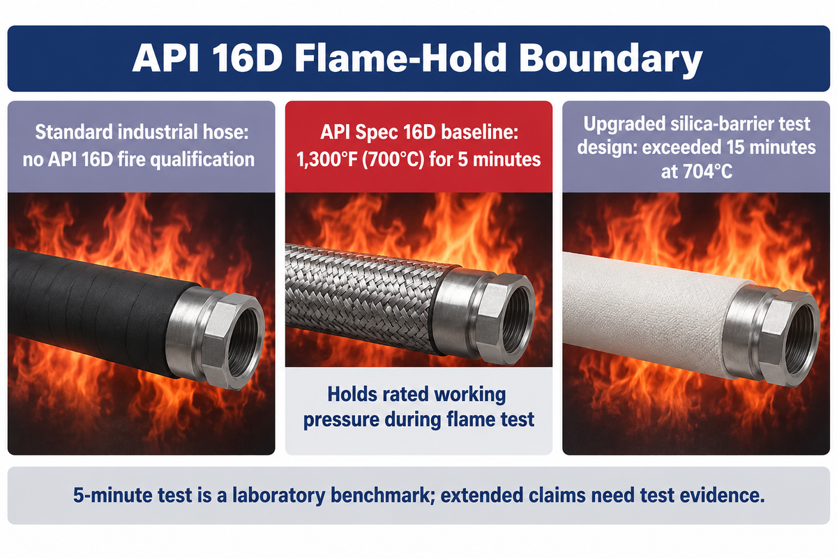
The API 16D Flame-Hold Boundary is a pressurized well-control fire test at 1,300°F (700°C) for 5 minutes under rated working pressure, which is different from an ordinary flame-retardant hydraulic cover that only resists unpressurized surface flame spread.
In circulating heat-exchanger tubing, liquid flows past the wall to carry heat away. In a BOP control line, on the other hand, hydraulic fluid is held under static or post-stroke pressure, after the preventer piston closes. Heat can soak through the outer jacket and degrade the inner tube inside the ferrule zone unless dedicated thermal insulation blocks radial heat flux. Thermal insulation is needed to block radial heat flow. US Patent Application US20120186684A1 and other patent literature describe hose designs that incorporate thermal barriers and intumescent outer elastomers to pass a 5-minute fire test at temperatures between 700°C to 750°C under the maximum working pressure of the design according to Lloyd’s Fire Test OD/1000/499 and API Spec 16D.
| Verification Parameter | Standard Industrial Hydraulic Hose | API Spec 16D Baseline Control Line | Upgraded Silica-Barrier BOP Assembly |
|---|---|---|---|
| Primary Governing Scope | General industrial hydraulic machinery | API Spec 16D Sec. 10.1.2.1 (Division 1 surface stack control lines) | API Spec 16D & Lloyd’s Register OD/1000/499 plus operator fire-endurance study |
| Flame Test Temperature | No API 16D fire qualification at rated hydraulic pressure | 1,300°F (700°C) direct flame envelope per API Spec 16D Sec. 10.1.2.1 | 704°C (1,300°F) hydrocarbon fire-test benchmark (700°C to 750°C in US20120186684A1) |
| Pressurized Hold Duration | Not qualified for pressurized hydrocarbon flame hold | 5 minutes minimum at rated working pressure | 5-minute API 16D baseline; best silica-barrier test design exceeded 15 minutes |
| Internal Fluid Condition | Continuous circulation assumed for heat rejection | Pressurized control fluid held at rated working pressure during fire test | Pressurized control fluid insulated by silica or ceramic fiber thermal barrier |
| Rated Working Pressure Class | Varies by industrial hose series | 3,000 psi (20.7 MPa) or 5,000 psi (35.0 MPa) | 3,000 psi (20.7 MPa) to 5,000 psi (35.0 MPa / 350 bar, Parker FA35-16 1-inch ID) |
| Minimum Burst Design Factor | Ambient burst rating only | 4:1 design factor at ambient plus 5-minute flame hold | 4:1 design factor (Parker FA35-16) plus extended thermal barrier retention |
| End Coupling Qualification | Standard crimp ferrule without fire-sleeve lock | Factory-crimped coupling tested as part of the complete assembly | Insulated crimp transition and matched V-series or OEM ferrule verified under flame load |
| Operational Survival Boundary | Unsuitable for well-control stack actuation | Laboratory type-test benchmark; sustained fire beyond 5 minutes can breach line | Extends actuator response window in tested designs; requires separate test evidence |
Passing a 5-minute laboratory flame test is a bounded type-test benchmark rather than an unconditional guarantee that a blowout preventer will close during a prolonged rig fire. A 2022 Drilling Contractor Report on BOP hydraulic hose upgrades indicates that during a blowout fire in 2018 in Oklahoma, hydraulic hoses that linked the accumulator unit to the BOPs failed prior to the attempt to close the BOPs. The API Spec 16D qualification specifies a test for 5 minutes at 704°C (1,300°F); when researchers tested four new hose designs incorporating a silica-based material against a commercial benchmark, the best design exceeded 15 minutes before failure, though any survival claim beyond 5 minutes requires separate test evidence for that specific hose design.
Multi-Layer BOP Hose Construction: Tube, Wire Spiral, Insulation and Armor
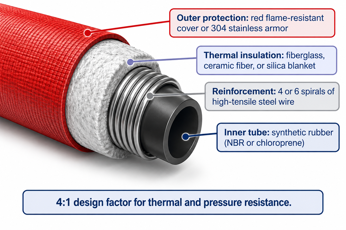
Examining the exterior of a hose assembly reveals little about its internal thermal margin. Both a smooth red polymer jacket and a corrugated stainless steel armor sleeve rely on an internal multi-layer composite to contain pressure while blocking heat transfer, so engineers review the published technical specifications of each layer before approving a rig bill of materials.
Because API 16D hoses are designed for hydraulic control rather than abrasive mud pumping, their innermost layer is an extruded synthetic rubber tube—such as nitrile (NBR) or chloroprene—formulated to handle water-glycol control fluids, lubricating oils, and petroleum-based hydraulic fluids. Surrounding that liner are four or six alternating spirals of high-tensile steel wire reinforcement which support a 3,000 or 5,000 psi mechanical load and provide impulse resistance during rapid closure of valves. Parker’s FA35-16 product page mentions its high-performance BOP hoses consist of an inner tube made of synthetic rubber, four or six spirals of high-tensile steel wire, and a 4:1 design factor for thermal and pressure resistance. On the other hand, Gates’ high-pressure oilfield hose overview, states that oilfield hoses must withstand high working pressures, temperatures and pressure pulses.
Over the wire reinforcement sits the thermal insulation package: layers of fiberglass, ceramic fiber, or silica blanket, paired with a flame-retardant elastomer. As described in US Patent Application US20120186684A1, some fire-resistant hose designs use intumescent polyurethane or rubber covers that form a charred carbonaceous foam layer during flame exposure, slowing heat transfer and helping protect the inner tube and crimp area while remaining thermally stable up to 305°F (152°C) or 350°F (175°C) during hose vulcanization.
Buyers choose between two external protection styles based on rig routing:
- A thick red cover of flame-resistant synthetic rubber or polyurethane resists moisture, washdown chemicals, and corrosion while providing high-visibility identification along the substructure.
- An interlocking or braided 304 stainless steel armor jacket wraps the thermal insulation layer in flexible metallic strip or wire. Inspectors must ensure the armor doesn’t pinch the hose wall.
Working Pressure Ratings: 3,000 psi vs 5,000 psi Accumulator Duty
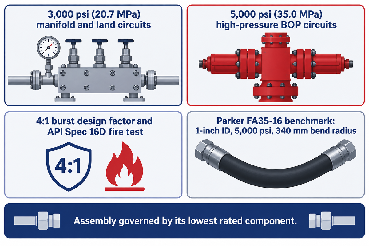
Selecting pressure ratings for well-control hoses starts with the maximum operating pressure of the accumulator unit and manifold circuits. Some offshore and high-pressure BOP circuits are designed at 5,000 psi (35.0 MPa), while other land and manifold circuits are at 3,000 psi (20.7 MPa); the hose rating must match the circuit’s specified maximum pressure. The hose rating must be the same as the circuits’ rated maximum pressure.
What pressure rating is required for a BOP control hose?
A BOP control hose must have a maximum working pressure at least equal to the circuit’s specified maximum pressure; 3,000 psi (20.7 MPa) and 5,000 psi (35.0 MPa) assemblies serve different system designs, and the complete assembly must meet the applicable 4:1 burst design factor and API Spec 16D fire-test requirement.
For a verified first-party product benchmark, Parker’s FA35-16 fire-resistant BOP hose specification lists a 1-inch (25.4 mm) inside diameter, a 1.535-inch (39 mm) outside diameter, a 35.0 MPa (350 bar / 5,000 psi) maximum operating pressure, a 4:1 design factor, and a 340 mm (13.386-inch) minimum bend radius, certified to withstand fire, high heat, and pressure under API 16D and Lloyd’s Register OD/1000/499 flame testing at 1,300°F for 5 minutes. Supplier catalog pages such as RigRS’s 16D hose overview also list both 3,000 psi and 5,000 psi working pressure options for accumulator units and BOP stacks; because Parker’s FA35-16 metrics apply specifically to that model, buyers must check the datasheet for the exact nominal bore and manufacturer series being ordered.
A 3,000 psi hose assembly shouldn’t be installed in a 5,000 psi accumulator or ram circuit, just because the thread size matches. The complete hose assembly is governed by its lowest rated component, which may include end adapters, hammer unions, and swivel joints.
Inside Diameter Sizing and API 16D Closing-Time Flow Loss
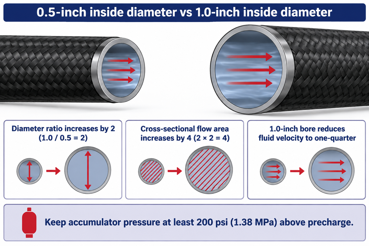
Selecting a BOP control hose solely by its 3,000 psi or 5,000 psi pressure rating while ignoring inside diameter can restrict hydraulic flow rate and actuator efficiency during an emergency closure. When closing a blowout preventer, the control line must deliver the required fluid volume fast enough to complete the stroke within the applicable well-control closing time.
In addition, the Railroad Commission of Texas clarification of API Standard 53 Section 6.5.6.2.2 states that during an accumulator drawdown test—where Note 1 recommends waiting a minimum of 1 hour after initially charging the accumulator system from precharge pressure to operating pressure—the final accumulator pressure recorded in Subsection (g) must remain equal to or greater than 200 psi (1.38 MPa) above precharge pressure.
Bore-Sizing Geometry Comparison: 0.5-Inch vs 1.0-Inch Inside Diameter
In line hydraulics, internal cross-sectional flow areas scale with the square of the inside diameter. Comparing a 1.0-inch inside diameter control hose (such as Parker FA35-16 at 1 inch / 25.4 mm ID) with a 0.5-inch inside diameter hose at the same volumetric flow rate illustrates why bore selection directly governs closing speed:
- Doubling the inside diameter from 0.5 inch to 1.0 inch increases the diameter ratio by 2 (since 1.0 / 0.5 = 2) and the internal cross-sectional flow area by 4 (since 2 × 2 = 4).
- Because average single-phase fluid velocity is inversely proportional to flow area at a fixed gallon-per-minute delivery rate, the 4-fold larger area of the 1.0-inch bore reduces fluid velocity to one-quarter of the velocity inside a 0.5-inch bore, cutting line pressure loss across long substructure runs so accumulator pressure stays above the API Standard 53 Section 6.5.6.2.2 minimum threshold of 200 psi (1.38 MPa) above precharge pressure.
Engineering Boundary:The actual pressure drop is determined by control-fluid viscosity at ambient rig temperature, hose length and elbow/swivel losses; the comparison above illustrates only single-phase continuity velocity. The comparison shown illustrates only single phase continuity velocity.
End Connections, Hammer Unions and Factory Crimp Integrity
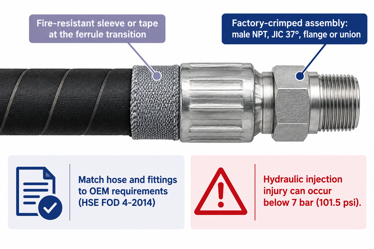
BOP control hoses are often supplied by the factory as crimped assemblies. Any field replaceable coupling would only be acceptable when the entire assembly is qualified for the service. Common terminations include male NPT tapered pipe threads, JIC 37° flare swivel nuts, API flanges, and hammer unions or quick-disconnect couplings, which are part of a qualified end-fitting.
The UK Health and Safety Executive (HSE) Safety Bulletin FOD 4-2014, which investigated a fatal hydraulic fluid injection incident, reported that although serious reported cases of hydraulic injection have occurred at pressures in excess of 100 bar (1,450 psi), injection injury can occur at pressures less than 7 bar (101.5 psi). To prevent coupling failure and possible fluid injection, FOD 4-2014 states that whenever replacement or maintenance takes place on a pressurized system, fittings should be matched and compatible with the original equipment manufacturer’s requirements, and the replacement should be treated as a pressure test with appropriate precautions. The exercise should be considered a pressure test and appropriate precautions taken.
Hose bodies, ferrules, inserts, and crimp dimensions should be used only in combinations qualified by the assembly manufacturer; an unqualified mix can invalidate the assembly’s pressure and fire-test qualification. During a 1,300°F (700°C) fire-test, the metal crimp collar acts as a heat bridge; as mentioned in US Patent Application US20120186684A1, the hydraulically crimped coupling area may include a fire-resistant sleeve or tape to compensate for the outer cover (material) at the ferrule transition.
Rig Floor Routing, Minimum Bend Radius and Heat-Shield Clearance
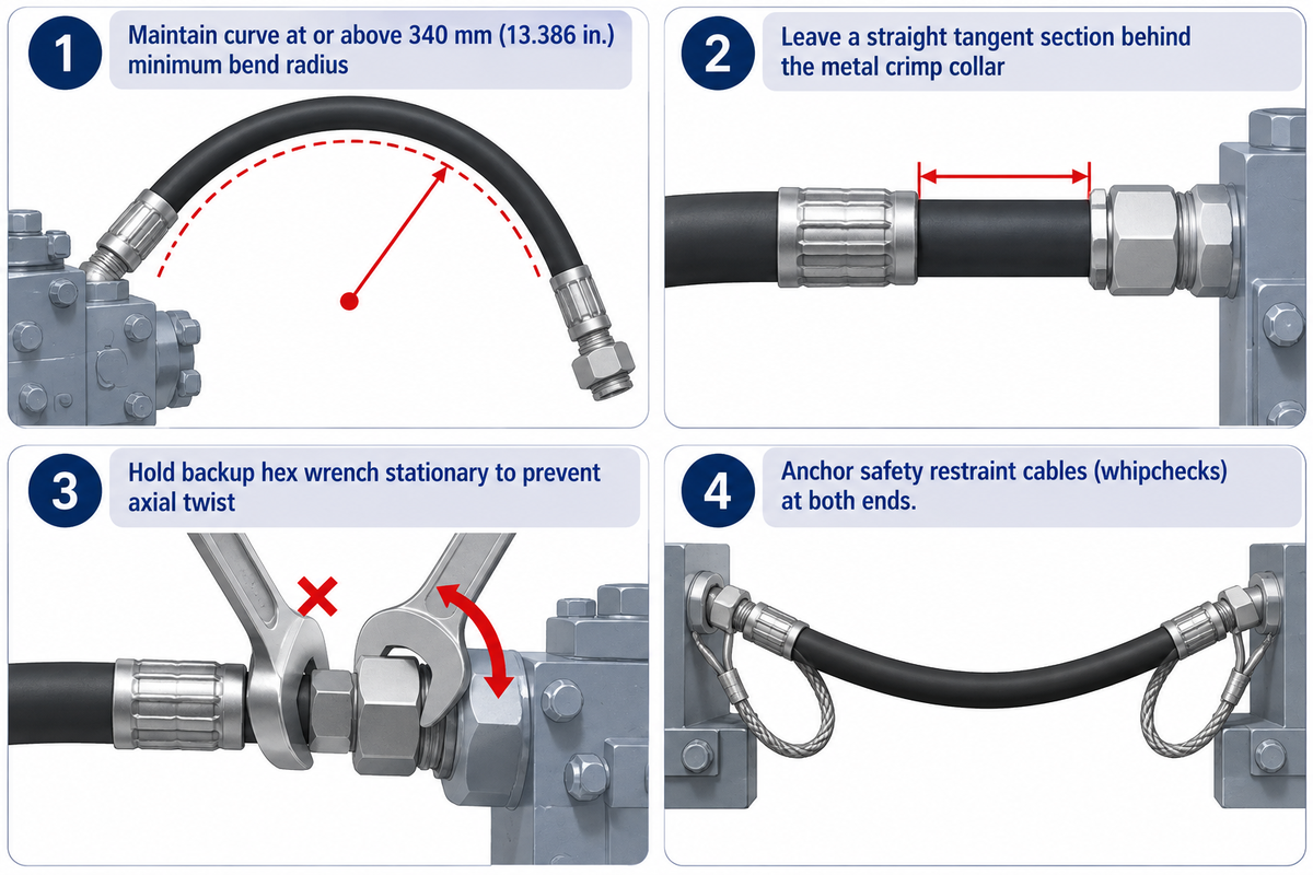
A certified 5,000 psi fire-resistant hose assembly can still fail early, especially if the installation crew forced the hose into a tight bend behind the ferrule, or if the line is subject to axial torsion during union make-up, or if it’s in contact with steel beams and grates in the cellar.
Field incident data demonstrates that routing discipline is an effective control safeguard. IADC Safety Alert 22-04 describes a subsea BOP incident in which the hotline control hose, and yellow and blue pod multiplexed communication (MUX) cables, were damaged as a result of too much tension during severe weather conditions and heave conditions, which resulted in partial loss of communications and pod functions. Installation crews on both surface and subsea stacks implement four mechanical routing rules to prevent routing failures:
- .
Maintain every curve at or above the minimum bend radius published for that part. For example, Parkers 1 inch FA35-16 specification has a minimum bend radius of 340mm (13.386 inches), and bending this part any tighter than 340mm can damage the reinforcing and/or the insulation and may decrease the life of the part.
- Leave a straight, unbent, tangent section of tubing behind the metal crimp collar, or use an angled adapter elbow to eliminate side loading at the ferrule shoulder.
- Prevent axial twist during union make-up; as piping engineers discuss in Eng-Tips flexible-hose application threads (contrasting 10,000 psi API drilling hoses with under-250 psig utility lines), twisting a wire-reinforced hose along its axis while tightening a union pre-stresses the spiral reinforcement, so crews should hold the backup hex wrench stationary while turning the swivel nut.
- Anchor safety restraint cables (whipchecks or hobble clamps) at both ends of every high-pressure control line so a parted coupling cannot whip across the cellar or walkways.
Field Inspection Schedules and Hydrostatic Proof Testing Limits
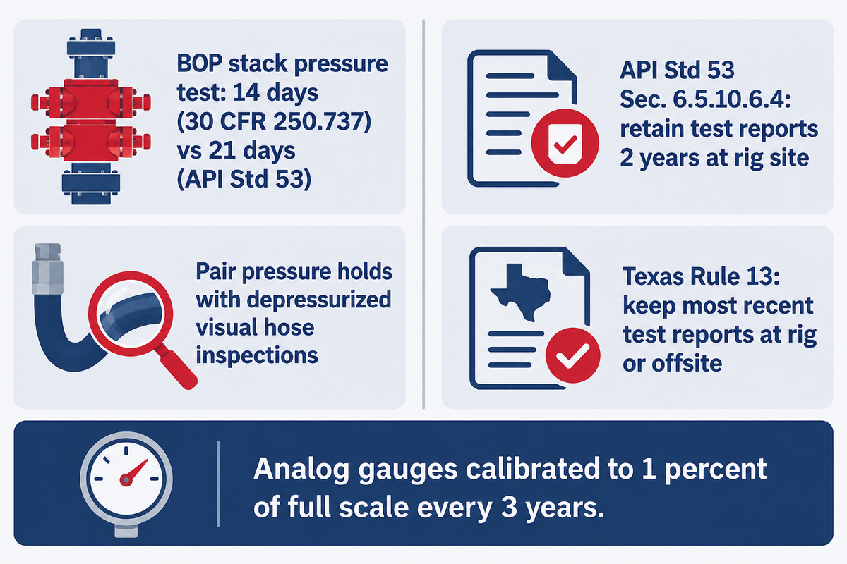
BOP stack pressure and function tests operate in accordance with the prescribed procedures; those stack tests, by themselves, don’t define a replacement or hydrostatic test interval for each control hose. In the oil and gas industry, maintenance teams pair scheduled pressure holds with depressurized visual inspections of each flexible control line.
In a 2015 regulatory research summary on stack testing, the U.S. Bureau of Safety and Environmental Enforcement (BSEE) Examination of Blowout Preventer Pressure Test Frequency (Project TCP 5010) noted that, at the time, the applicable federal regulation required BOP stack pressure tests at least every 14 days with the BOP installed on the well, and the industry standard API Standard 53 required such testing every 21 days. Note that 30 CFR 250.737 is a BSEE regulation provision governing BOP system testing rather than a study of hose remaining life, and routine pressure holds do not provide a quantitative remaining-fatigue-life calculation for every BOP hose assembly.
In Oilfield Technology’s June 2025 engineering report on choosing the right hose, authors note that selecting hoses with proven performance reduces operating expenditure and supports ongoing operation feasibility. For test records, API Standard 53 Section 6.5.10.6.4 states that pressure and function test reports shall be retained for a minimum of 2 years at the rig site with copies kept at a designated offsite location, while the Railroad Commission of Texas clarifies that under Texas Rule 13 only the most recent pressure and function test reports must be kept at the rig site or an offsite location. Additionally, API Standard 53, Section 6.3.10.6, states that control system analog pressure gauges shall be calibrated to 1 percent of full scale at least every 3 years, and the Railroad Commission of Texas accepts calibration to OEM specifications as part of the owner’s inspection and maintenance program.
Recognizing Damage: The Crimp-to-Armor Retirement Matrix
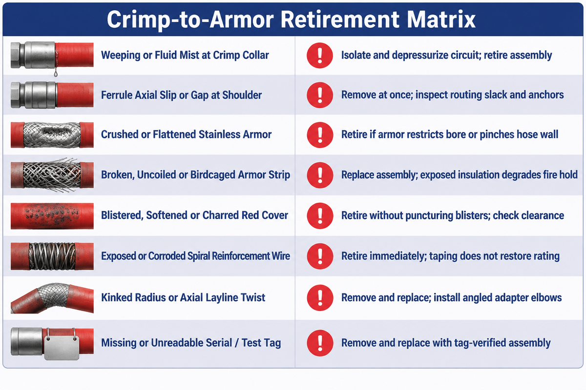
Because static stack pressure tests do not measure internal elastomer aging, rig mechanics conduct structured visual and tactile inspections only after the line is isolated and bled to zero pressure, to retire damaged assemblies before a leak or coupling blow-off occurs. Replacing an assembly is done before a leak or blow down of a coupling occurs. Industry maintenance guides such as Meyer’s BOP inspection and maintenance guide note that common causes of BOP failure include worn seals, hydraulic leaks, corrosion, control system problems, poor maintenance, incomplete testing, and debris, and recommend inspecting hoses and connections before each well and after heavy use.
Crimp-to-Armor Retirement Matrix
The Crimp-to-Armor Retirement Matrix covers eight observable field defect categories from the metal crimp collar to the outer armor, matching each physical failure mechanism to a specific rig maintenance action.
| Observed Damage Category | Physical Failure Mechanism | Rig Maintenance Action |
|---|---|---|
| Weeping or Fluid Mist at Crimp Collar | Inner liner seal breach or ferrule grip relaxation; severe hydraulic-injection hazard (HSE FOD 4-2014). | Isolate and depressurize accumulator circuit immediately; retire assembly from service. |
| Ferrule Axial Slip or Gap at Shoulder | Excessive tensile pull (IADC Alert 22-04) or loss of swage engagement. | Remove from service at once; inspect routing slack, whipcheck anchors, and manifold support. |
| Crushed or Flattened Stainless Armor | Mechanical impact or pinch load compressing thermal barrier and ovalizing wire spirals. | Retire assembly if armor indentation restricts bore or pinches underlying hose wall. |
| Broken, Uncoiled or Birdcaged Armor Strip | Loss of outer mechanical shield and exposure of fiberglass or silica fire insulation. | Replace assembly; exposed thermal insulation absorbs moisture and oil, degrading fire hold. |
| Blistered, Softened or Charred Red Cover | Fluid permeation through inner tube or localized radiant heat degradation of polymer jacket. | Retire assembly without puncturing blisters; check heat-shield clearance and fluid compatibility. |
| Exposed or Corroded Spiral Reinforcement Wire | Deep cover abrasion allowing rig washwater and brine to corrode pressure-bearing steel wire. | Retire assembly immediately; taping over an abraded jacket restores neither burst nor fire rating. |
| Kinked Radius or Axial Layline Twist | Bending tighter than minimum bend radius (340 mm on 1-inch FA35-16) or union make-up torsion. | Remove and replace; install angled manifold adapter elbows to correct routing geometry. |
| Missing or Unreadable Serial / Test Tag | Loss of traceability to hydrostatic proof chart, working pressure rating, and API 16D qualification. | Remove assembly from active manifold service and replace with a tag-verified, pressure-tested assembly. |
In patent background literature, US Patent Application US20040065377A1 describes an embedded electrical wear-monitoring system designed to detect internal hose wall degradation before rupture in industrial transfer lines; because standard API Spec 16D hoses don’t require embedded electronic sensors, rig crews rely on depressurized physical inspection against the 8 defect categories above.
Do (Rig Floor Best Practices)
- Bleed accumulator manifold pressure to 0 psi and lock out valves before inspecting or disconnecting any control hose.
- Confirm that replacement hose and crimp fittings are matched and compatible per OEM specifications as stated in UK HSE FOD 4-2014.
- Retain hydrostatic and function-test charts for the period required by the applicable API Standard 53 Section 6.5.10.6.4 recordkeeping provision, operator procedure, or contract.
Don’t (Critical Safety Prohibitions)
- Never run a gloved or bare hand along a pressurized hose to check for pinhole leaks (hydraulic injection risk occurs as low as 7 bar / 101.5 psi).
- Never hammer or tighten a weeping union while the control line holds accumulator pressure.
- Never wrap damaged fire jackets with utility tape to bypass replacement.
Sourcing BOP Hose Assemblies, Documentation and Traceability
When purchasing replacement well-control lines, professional buyers differentiate 3 supply chain roles: (i) the base elastomer/wire hose manufacturer (e.g. Parker Hannifin or Gates), (ii) the qualified assembly fabricator that crimps and hydrostatic-tests the finished line, and (iii) the integrated supply chain partner that coordinates multi-item rig packages, third-party inspection, and export documentation. Among the public sources reviewed in this guide, Parker’s FA35-16 product datasheet explicitly confirms both API Spec 16D and Lloyd’s Register OD/1000/499 fire-test approval for that 5,000 psi assembly, whereas Gates’ oilfield hose overview page and distributor catalog summaries describe general oilfield hose product families without publishing an assembly-specific Lloyd’s Register certificate on those overview pages.
The API Subcommittee 16 Series 16 standards scope outlines the difference in equipment scope between API Spec 16D and API Spec 7-1; therefore, holding a credential to API Spec 7-1 does not confirm compliance to API Spec 16D for a BOP hose assembly. Established in 2001, China Welong (Shaanxi Welong International Supply Chain Management Co., Ltd.) operates as an international, integrated supply chain service provider holding ISO 9001:2015 quality management system and API Spec 7-1 certifications for the applicable drilling tools, and serves customers in the United States, the United Kingdom, Germany, Romania, Italy, the Netherlands, UAE, Australia, Argentina, Brazil, South Africa and other markets.
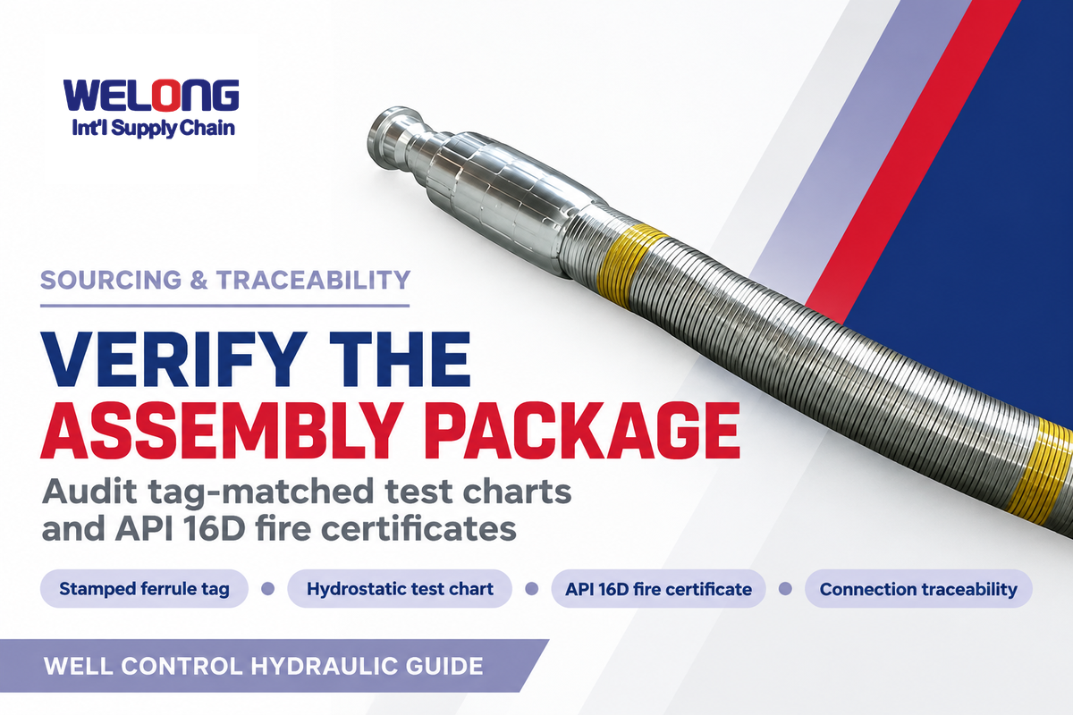
Company-level ISO 9001:2015 or API Spec 7-1 certifications cover quality management and rotary drilling tool manufacturing; therefore, they do not provide type approval for API Spec 16D, and procurement teams ordering BOP control lines should specify and audit an assembly-level test and certificate package. Procurement teams ordering BOP control lines should require and audit an assembly-level test and supporting certificates. To verify the four required assembly-level records, use our interactive hose documentation and paper-trail builder:
- Verify the permanent ferrule stamping or stainless metal tag against the paper dossier to confirm the physical assembly serial number, nominal bore, working pressure of 3,000 psi or 5,000 psi, and test date.
- Reference the assembly-specific hydrostatic proof-test chart to verify factory proof-pressure hold time and pressure recorder data for that specific serial number.
- Audit the API Spec 16D and Lloyd’s Register OD/1000/499 type-approval certificate reference to confirm that the exact hose-and-coupling combination passed the 1,300°F (700°C) 5-minute flame test.
- Confirm the end-connection dimensional and material traceability record covering the thread form (NPT, JIC 37°, flange, or union) and wetted stem material.
To review available armored and red polymer hose options, custom assembly lengths, and project quotations, visit our dedicated BOP hose assemblies and custom specifications page.
Engineering Takeaway & Specification Review
Specify every BOP control hose assembly by its complete duty envelope: verified API Spec 16D 1,300°F (700°C) 5-minute flame-hold qualification, 3,000 psi or 5,000 psi working pressure matched to the circuit, bore diameter sized to keep accumulator drawdown at least 200 psi above precharge pressure, OEM-matched crimped fittings, and tag-matched hydrostatic test records.
Frequently Asked Questions
What does BOP stand for on a hydraulic hose?
Blowout Preventer in oilfield drilling; Battery Operated Pump in workshop catalogs.
In oilfield drilling and well control, BOP stands for Blowout Preventer, and a BOP hose carries high-pressure hydraulic control fluid from the accumulator unit to actuate the preventer stack. Outside the oilfield, some workshop lubrication catalogs use BOP for Battery Operated Pump grease transfer hoses, which are never rated for well-control service.
What color is an API 16D BOP control hose?
Bright red polymer jacket or silver stainless-steel armor with red markings.
Most API Spec 16D BOP control hoses feature either a bright red flame-resistant outer polymer cover or an exposed silver 304 stainless-steel braided or interlocked armor jacket with red identification markings. The red coding helps rig crews visually distinguish emergency well-control hydraulic lines from ordinary utility hoses on the rig floor.
Can a standard hydraulic hose be used on a blowout preventer?
No; an unqualified industrial hose lacks API 16D fire-test approval and matched fire sleeves.
No, an ordinary industrial hydraulic hose without API Spec 16D qualification cannot replace a certified BOP control hose on a Division 1 surface well-control stack. Even if the ambient working pressure matches 3,000 or 5,000 psi, unqualified hoses lack the tested thermal insulation layers and fire-qualified crimped couplings needed to maintain rated working pressure at 1,300°F (700°C) for 5 minutes.
Are reusable fittings allowed on BOP control hoses?
BOP hoses are supplied as factory-crimped assemblies unless a coupling is specifically qualified.
BOP control hoses are commonly supplied as permanently crimped or swaged factory assemblies, and any field-replaceable coupling is acceptable only when the complete hose-and-fitting combination holds valid pressure and API Spec 16D fire-test qualification for that service. UK HSE FOD 4-2014 requires that replacement hose and fittings be matched and compatible per OEM specifications.
How do you choose the right BOP hose assembly for a drilling rig?
Match circuit working pressure, closing-time bore flow, API 16D fire rating, and end fittings.
Start by confirming the accumulator circuit’s specified maximum working pressure, such as 3,000 psi (20.7 MPa) or 5,000 psi (35.0 MPa), and select an inside diameter that limits pressure drop and keeps accumulator drawdown at least 200 psi above precharge pressure. Next, verify that the complete hose-and-fitting assembly holds current API Spec 16D (1,300°F / 700°C for 5 minutes) fire-test approval, confirm compatibility with your water-glycol or mineral control fluid, and match the end connections, minimum bend radius, and outer armor style to the rig’s routing path.
Does stainless steel armor increase a hose’s working pressure?
No; internal high-tensile wire spirals carry the working pressure.
External stainless steel armor protects the hose against abrasion and crushing, whereas the internal steel wire spirals carry the hydraulic working pressure. Crushed armor still requires inspection because it can pinch the insulation layer.
What documents should be delivered with a replacement BOP hose assembly?
Tag-matched hydrostatic test chart, serial number, working/test pressure, and API 16D fire-test reference.
A replacement well-control hose package should link the physical metal tag or permanent ferrule stamping on each assembly to its hydrostatic proof-test chart, assembly serial number, working and test pressure ratings, end-connection drawing, and the applicable API Spec 16D or Lloyd’s Register OD/1000/499 fire-test type-approval reference. Procurement teams should check that these records identify the actual swaged assembly and production batch rather than relying on a general company brochure or an unrelated quality-management certificate.
Contact China Welong’s engineering supply team with your nominal bore, working pressure, end termination drawing, and required test records.
Editorial and Scope Disclosure: This engineering guide is based on publicly available federal and state well control laws and regulations, scope of the API Subcommittee 16 standards, published patent disclosures, and named manufacturer product specifications. Illustrative flow-area comparisons demonstrate engineering principles and do not replace rig-specific hydraulic modeling. Background information about China Welong is included.
References & Sources
- Railroad Commission of Texas, Rule 13 Clarification of Well Control Issues (API Spec 16D Sec. 10.1.2.1 & API Std 53 Sec. 6.3.11.2.5 / 6.5.6.2.2 / 6.5.10.6.4)
- American Petroleum Institute, Subcommittee 16 (SC 16) Drilling Well Control Equipment Standards Scope
- U.S. Bureau of Safety and Environmental Enforcement (BSEE), Examination of Blowout Preventer Pressure Test Frequency (30 CFR 250.737 / TCP 5010)
- UK Health and Safety Executive (HSE), Safety Bulletin FOD 4-2014: Hydraulic Injection Injury and Matched Hose Fittings
- International Association of Drilling Contractors (IADC), Safety Alert 22-04: MUX Cables and Hotline Hose Damage
- Drilling Contractor (IADC), Well-Control Readiness and BOP Hydraulic Hose Fire-Endurance Qualification
- Oilfield Technology, Choosing the Right Hose for Oil and Gas Operations (June 2025)
- U.S. Patent Application Publication US20120186684A1, Flame Resistant Hose Construction and Method (API 16D & Lloyd’s Register OD/1000/499)
- U.S. Patent Application Publication US20040065377A1, Wear Indicator and Detector for Hoses