Get in touch with Welong Company
Oilfield Hoses
Oilfield Hoses: API 7K, 16C and 16D High-Pressure Lines for Drilling and Well Control
China Welong coordinates oilfield-hose supply against the rig circuit, pressure specification, end connection and document requirements. The quotation identifies the responsible manufacturer, assembly route and inspection scope for the selected hose.
- 1/2″ – 5″ BORE
- Up to 15,000 PSI
- −40 °C – +121 °C
- SOURCING + QC, NOT THE MILL
3
Rig circuits covered — mud, hydraulic control, well-control return
1/2″–5″
Bore range across the three families (12.5–127 mm)
Maximum 15,000 psi
Highest class quoted, on choke & kill, as a custom build
−40 °C
Lowest service temperature, set by the control line
2001
Supplier and quality-control coordination
0
The responsible manufacturer and the specification scope are named and verified on every quotation.
Two Products Share the Name “Oilfield Hose”:
Petroleum Transfer Hose vs High-Pressure Drilling Hose
The Two Oilfield Hoses, how to tell in one question
Ask what the hose is connected to — OSHA’s illustrated glossary names the components of each drilling circuit if you need to place it. If it runs between a tank, a truck or a pump skid and moves product from A to B at a few hundred psi, it’s a transfer hose and nothing on this page applies to it.
If it’s bolted into the drill string circuit, the blowout preventer control circuit or the choke and kill circuit, it’s a pressure-containing component of a well control system, and the governing specification is API 7K, API 16D or API 16C respectively.
Why the wrong hose does not simply leak a bit
The US Bureau of Safety and Environmental Enforcement documented a 5,000 psi maximum-working-pressure hydraulic hose that blistered and leaked at 2,500 psi – half its rating — because the medium running through it was nitrogen rather than the fluid it had been selected for.
BSEE’s own corrective guidance names seven selection inputs, not one:
- 01. size
- 02. temperature
- 03. application
- 04. material to be conveyed
- 05. pressure
- 06. ends or couplings
- 07. delivery
The Association for Hose and Accessories Distribution states the position plainly:
“Although there are standards published by manufacturers and independent testing organizations … which relate to hoses and hose fittings, there are no generally recognized standards for hose assemblies.”
Not sure which of the three circuits your line belongs to?
Walk the three circuits below →The Three-Circuit Rig Walk: Drilling Hose, BOP Hose and Choke & Kill Hose on One Rig
The hydraulic control circuit is the one most buyers treat as plumbing. Analysis prepared for BSEE by Argonne National Laboratory found the opposite: control-system failures accounted for 51%, 46%, 57% and 63% of blowout preventer failures across the datasets examined, and concluded that:
“about half of BOP failures are control system related.”
Drilling Contractor reported a 63% share for the control system back in 2009. A 2025 review in the SPE’s Journal of Petroleum Technology put hydraulics at more than 60% of system failures.
What each circuit actually connects to
Mud circulation — the mud pump discharges through the standpipe manifold and the rotary drilling hose carries drilling mud up to the goose-neck at the swivel or top drive. From the swivel it turns down the drill pipe and back up the annulus, and the return leg brings cuttings to the shakers. Pumping mud through a joint that moves is what a flexible connection exists for, because rigid pipe cannot follow the traveling block.
Hydraulic control — the accumulator unit stores hydraulic pressure and the control lines deliver it to the annular blowout preventer and to each ram blowout preventer on the stack. Ram-type and annular units both close on command carried by these lines, and on a subsea stack the same function is routed through the control pod.
Well-control return — once formation pressure enters the wellbore, the choke and kill hoses connect the stack outlets through the drilling spools to the choke manifold. The choke line takes returns out of the annulus and the kill line pumps heavy fluid back in, bringing pressure in the well back to something the crew can hold.
Blowout prevention depends on fluid flow through all three circuits staying controllable at once, which is why well control equipment is audited as a system rather than as a parts list. Onshore and offshore drilling rigs run the same three circuits, and geothermal wells drilled at comparable well pressure use the same equipment classes.
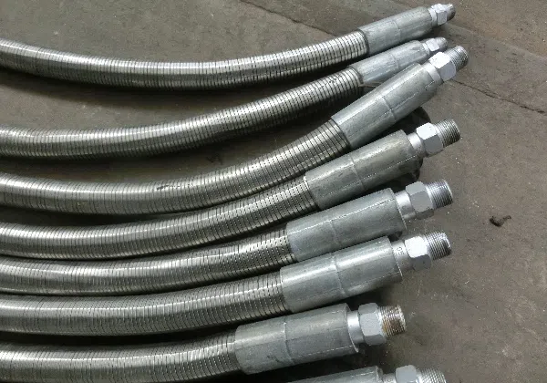
What Welong supplies, and what it does not
Scope map for this catalogue. Mount points follow the definitions published in OSHA’s Oil and Gas Well Drilling and Servicing eTool illustrated glossary. Pressure and bore figures are Welong published figures.
| Line | Circuit | Carries | Governing spec | Bore | Working pressure | Supplied? |
|---|---|---|---|---|---|---|
| Rotary / kelly hose | Mud circulation | Drilling fluid | API 7K | 2″–5″ | 4,000–15,000 psi | Yes — see product card |
| Rotary vibrator hose | Mud circulation | Drilling fluid, pump pulsation | API 7K | 2″–5″ | 5,000–7,500 psi | Yes — see product card |
| Dragchain hose | Mud circulation | Drilling fluid, offshore dragchain duty | API 7K | 2″–5″ | per duty | Yes — see product card |
| BOP control hose | Hydraulic control | Control fluid | API 16D | 1/2″–1-1/2″ | 5,000 / 10,000 psi | Yes — see product card |
| Choke & kill hose | Well-control return | Returns, kill fluid, gas, H₂S service | API 16C | 2″–4″ | 5,000–15,000 psi | Yes — see product card |
| Jumper / mud booster hose | Mud circulation | Drilling fluid | API 7K | — | — | Not in this catalogue |
| Cementing hose | Cementing | Cement slurry | API 7K | — | — | Not in this catalogue |
| Motion compensator hose | Heave compensation | Hydraulic fluid | — | — | — | Not in this catalogue |
| Marine riser / decoking hose | Riser / refinery | Various | — | — | — | Not in this catalogue |
| Frac / stimulation hose | Stimulation | Frac fluid, proppant | — | — | — | Not in this catalogue |
| Hammer unions, safety clamps | All three | End connections and restraint | per line spec | to suit | to suit | Quoted with the assembly |
THREE CIRCUITS, THREE SPECIFICATIONS — The three product lines
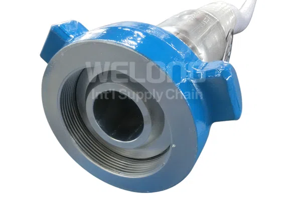
01 — MUD CIRCULATION · API Spec 7K
Full drilling hose specifications →
Drilling Hose (Drilling / kelly / rotary hose)
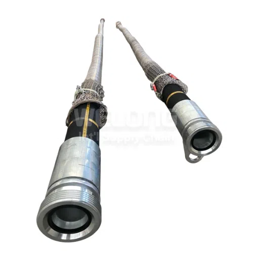
API 7K rotary drilling hose, kelly hose and vibrator hose between the mud pump, standpipe and swivel.
RouteMud pump → standpipe → swivel
Carriesdrilling fluid
Bore2″ – 5″ (50.8 – 127 mm)
Working pressure4,000 – 15,000 psi
GradesC (4,000) · D (5,000) · E (7,500) + 10,000 / 15,000 tiers
Temperature−25 °C to +121 °C
Max single length60 m (≈197 ft)
TypesRotary · Vibrator · Dragchain
Also listed asAPI 7K hose · API 7K drilling hose · drilling rotary hose · drilling and vibrator hose
Quote inputsBore · class · length · end fitting · inspection level · Incoterm
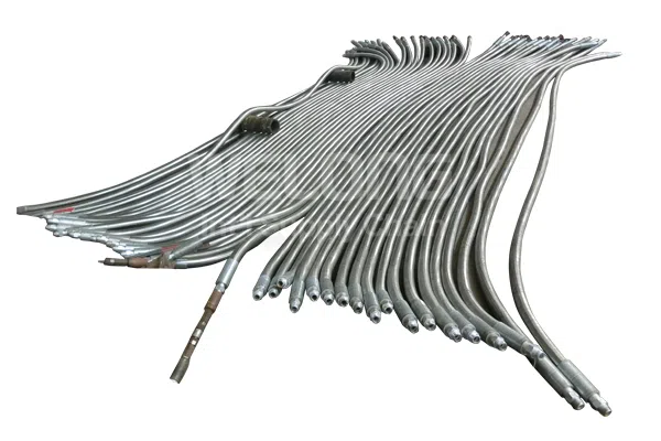
02 — HYDRAULIC CONTROL · API Spec 16D
Full BOP hose specifications →
BOP Hose (BOP control hose)
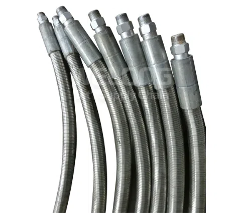
Fire-resistant control lines from the accumulator unit to the blowout preventer stack.
RouteAccumulator → BOP stack
Carrieshydraulic control fluid
Bore1/2″ – 1-1/2″ (12.5 – 38 mm)
Working pressure5,000 psi (34.5 MPa) · 10,000 psi (69 MPa)
Min. bend radius210 / 280 / 360 / 460 / 560 mm by bore
Temperature−40 °C to +121 °C — the coldest of the three
ConstructionsStainless-steel armor · high-molecular polymer
Quote inputsBore · class · length · connection type · cover type
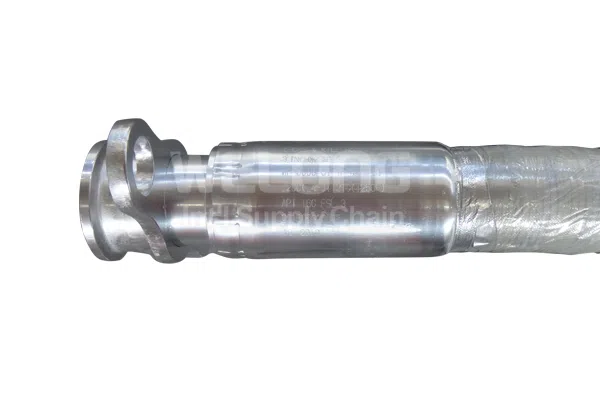
03 — WELL-CONTROL RETURN · API Spec 16C
Full choke & kill specifications →
Choke & Kill Hose
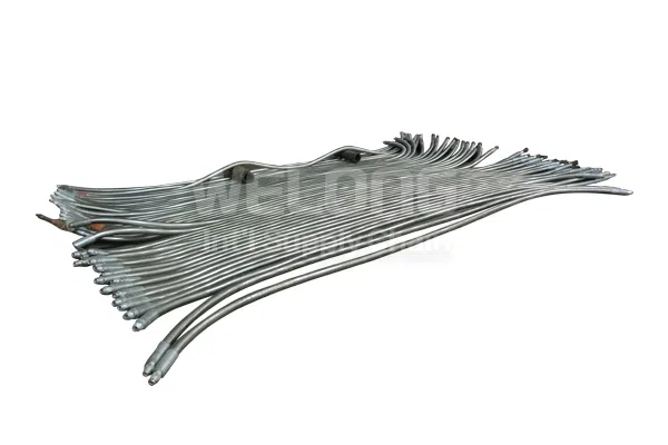
Armored flexible lines between the BOP stack and the choke and kill manifold.
RouteBOP stack → choke / kill manifold
Carriesreturns, kill fluid, gas
Bore2″ – 4″ (50.8 – 101.6 mm), incl. 2.5″ and 3.5″
Working pressure5,000 / 10,000 / 15,000 psi · model-specific pressure confirmed up to 15,000 psi
Min. bend radius1,200 – 1,800 mm by bore and class
Temperature−25 °C to +121 °C
ServiceH₂S — NACE MR0175 / ISO 15156 on request
ConstructionsStainless-steel armor · wear-resistant cover
Specifying more than one circuit on the same rig? Check where the pressure classes line up →
Oilfield Hose Sizes, Pressure Ratings and Bend Radius Across Three Standards
Compared across all three families, the envelopes don’t nest: control-circuit pressure stops at 10,000 psi while the other two reach 15,000 psi and above, and that same circuit runs 15 °C colder than either of them.
| Parameter | Drilling hose (API 7K) | BOP hose (API 16D) | Choke & kill (API 16C) |
|---|---|---|---|
| Bore range | 2″–5″ / 50.8–127 mm | 1/2″–1-1/2″ / 12.5–38 mm | 2″–4″ / 50.8–101.6 mm |
| Discrete bores offered | 2, 2½, 3, 3½, 4, 5″ | ½, ¾, 1, 1¼, 1½″ | 2, 2½, 3, 3½, 4″ |
| Working pressure classes | 4,000 / 5,000 / 7,500 / 10,000 / 15,000 psi | 5,000 / 10,000 psi | 5,000 / 10,000 / 15,000 psi (model-specific pressure confirmed up to 15,000 psi) |
| In MPa | 27.6 / 34.5 / 51.7 / 69 / 103.4 | 34.5 / 69 | 34.5 / 69 / 103.4 |
| Highest class available | 15,000 psi | 10,000 psi | Up to 15,000 psi, confirmed by quotation |
| Min. bend radius | not published per class | 210–560 mm | 1,200–1,800 mm |
| Service temperature | −25 °C to +121 °C (−13 °F to +250 °F) | −40 °C to +121 °C (−40 °F to +250 °F) | −25 °C to +121 °C (−13 °F to +250 °F) |
| Sour service | H₂S resistant, specified separately | not a published option | H₂S, NACE MR0175 / ISO 15156 on request |
| Max continuous length | 60 m | quoted per run | quoted per run |
Cross-family envelope. All figures in this table are Welong published figures taken from the product data behind the three child pages, converted to dual units where the source gives one. They are not reproductions of standard text — see the ratio-source table below before quoting any ratio.
The One-Rig Class Alignment, three consequences for a combined order
The One-Rig Class Alignment, three consequences for a combined order
So a rig quoted at 15,000 psi on mud and well control lines still uses 10,000 psi on the control circuit since 10,000 psi is the high limit of the 16D range in print. An equipment package for “15,000 psi throughout” can thus not be assembled from this catalogue.
Low-temperature floor for the package is set by the two lines nobody checks. Both the mud line and the choke and kill line stop at −25 °C while the control line runs to −40 °C, so a winterized or arctic spread is limited by the large-bore lines, not the small one.
Bend radii differ by a factor of more than eight too: a 1/2″ control line turns inside 210 mm; a 4″ choke and kill line needs up to 1,800 mm. Routing envelopes drawn for one circuit do not transfer to another.
A higher pressure class costs you routing freedom
A higher pressure class costs you routing freedom
The minimum bend radius isn’t static — it grows with the pressure class, because the reinforcement package grows with it. Pacific Hoseflex’s documented API 7K class table, for instance, shows a 2″ hose moving from 800 mm at its lowest class to 1,000 mm at its highest, and a 3″ hose from 950 mm to 1,150 mm.
How the three families are built
How the three families are built
Hose construction across all three families follows one outline and separates on the detail that matters. These are flexible hoses doing a rigid pipe’s job, so every layer is a pressure-containing element rather than a covering.
- Inner tube a resistant synthetic rubber compound chosen for the medium. Hydrogen sulfide service is specified separately, because H₂S attacks both the elastomeric liner and the metallic components behind it.
- Reinforcement layers alternating helical steel wire. Layer count sets the pressure class, and it also sets the stiffness that reappears later as minimum bend radius.
- Cover abrasion and corrosion resistance on the mud lines, fire resistance where the route demands it, stainless-steel armor on the two well-control circuits.
End connections are union, flange or integral forged fittings, qualified together with the assembly rather than added to it afterwards. Oilfield hose fittings bought separately and crimped later are a different product with a different qualification history.
Inside diameter is quoted as the nominal bore because bore, not the outside dimension, governs fluid flow and pressure drop. Temperature resistance is also separate from pressure, and a flexible high-pressure assembly fails at its weakest layer — sharp bends below the published minimum radius damage the reinforcement long before pressure does.
Before you uprate a line “to be safe”
Uprating adds reinforcement, which adds stiffness, which enlarges the minimum bend radius. On a congested stack or a dragchain run, the higher class may not physically route.
Those Pacific Hoseflex figures are indicative manufacturer data, published by that vendor for its own product — not an API rule, and not Welong’s. Bend radius is quoted against the specific assembly.
The size you buy is the size you have to file
On the U.S. Outer Continental Shelf, choke and kill line dimensions are not just an engineering choice — they are a regulatory submittal. 30 CFR 250.731, the BOP information a lessee must submit includes the location and size of the choke and kill lines, on more than one of the required documents.
Get Instant Quote →Pressure Test Coverage: What It Proves and Where It Stops
The International Association of Drilling Contractors issued a safety alert after two high-pressure hoses failed, and the sentence that matters is this one: “Pressure testing alone does not necessarily ensure that the high-pressure hose will not fail.”
The alert adds that “both of these hoses failed shortly after the high-pressure mud system including the hoses was pressure-tested to rated working capacity.”
The Proof-Test Gap
Hydrostatic testing gives you a snapshot of a single assembly under static water pressure on one specific day. But service is cyclic, hot, abrasive, sometimes sour, and routed around obstructions.
BSEE recorded an incident that demonstrates the difference: a hose that passed a 10,000 psi test for 10 minutes went on to cause an injury during bleed-down at 6,000 psi. The certificate was correct — the assembly did hold 10,000 psi for 10 minutes under water. But it wasn’t a prediction.
Factory test and field test are not the same number
API’s own recommended practice for inspection and maintenance of drilling equipment caps field re-testing well below the delivery test. That cap is set out in API RP 7L, Appendix A.13: “field test pressure not to exceed 1.25 times the maximum rated working pressure … regardless of the delivery test pressure involved.”
VIEW DELIVERY VS FIELD TEST DEF
- Delivery test — performed once, at the factory, at the ratio the governing specification or the manufacturer sets.
- Field test — performed repeatedly over the hose’s life, and capped by API RP 7L at 1.25× working pressure.
Applying the delivery ratio in the field is a documented way to damage a hose that was in serviceable condition.
What service life actually depends on
- Cyclic loading vs Date: No published replacement interval covers all three families, and duty cycle rather than calendar date determines service life. Cyclic loading causes pressure resistance to degrade from the inside outward while the cover deteriorates from the outside inward.
- Cycles cost more than hours: Every time you pressurize and bleed a line you spend some of its life, so a line cycled twice a shift ages faster than one held at full working pressure continuously.
- Routing is cumulative: every bend tighter than the published minimum radius is a permanent debit against the reinforcement.
- Operational Safety: Safety clamps and whip restraints are an operational safety requirement rather than an accessory, and their absence turns a leak into an incident.
- Governance: API RP 7L covers inspection, maintenance and repair of drilling equipment, and it is the document to hold a mud-circuit program against.
Which ratios are actually written into a standard
Most supplier pages — including some that rank well — state a ratio and attribute it to a standard without naming a clause. One ratio on this page is reproduced verbatim from API’s own published document; the others are attributed to whoever actually published them.
Ratio source. Read the “attributable to” column before quoting any figure in a specification. Where a ratio is a Welong published figure, verify it against the edition of the standard you actually purchase — three separate renumbering events are documented across these three specifications.
What to ask for instead of a ratio
Request the test report for your batch showing the actual pressure applied, the hold time, and the results achieved. Don’t ask for a ratio quoted from a specification the supplier may never have opened.
Then ask which edition of the specification the report was prepared against. Addendum 1 to API Spec 16C deleted a section and renumbered everything following it; the 3rd Edition renumbered again; the 16D fire clause moved between editions; and 7K’s hose clause was renumbered and renamed. A clause number without an edition is not a citation.
Where a Fire Rating Actually Comes From, and What FSL Really Means
FSL is printed across this category as “Fire Service Level”. API’s own Spec 7K paperwork expands FSL as “Flexible Specification Level”. It is not a fire rating, and reading it as one leads buyers to specify the wrong thing.
The FSL Misreading — what each specification’s level ladder actually grades.
FSL selection under API 16C applies to flexible choke and kill lines specifically, not to rigid lines, chokes, manifolds or actuators.
| Specification | Levels published | What the ladder grades | Where a fire test sits |
|---|---|---|---|
| API Spec 7K | FSL 0 · 1 · 2 | Pressure-pulsation cycling duty for high-pressure mud and cement hoses | A fire rating on a mud hose is bought as an option and qualified elsewhere — see the row below |
| API Spec 16C | FSL 0 · 1 · 2 · 3 | Flexible choke and kill line service severity | Not blanket. Fire testing applies at FSL 1 and FSL 3; FSL 0 carries none; FSL 2 substitutes a 177 °C internal test |
| API Spec 16D | – | Control systems for drilling well control equipment | Control-line fire criteria are set in the specification’s fire test section, at 1300 °F / 700 °C |
| Lloyd’s Reg. | pass / fail | An independent fire test route, used alongside the API specifications | Often quoted at 1300 °F (704 °C) for 30 minutes with bonded couplings |
| ABS/UL 1114 | pass / fail | Class rule route rather than product standard | ABS requires flexible piping carrying combustible fluids to be fire-resistant to UL 1114 or another recognized standard |
1300 °F is one number with two conversions, and they are not the same standard
API 16D’s control-line fire criterion is published as 1300 °F / 700 °C. For choke and kill, 16C publishes 704 °C. Fahrenheit is shared; the Celsius figures are not, and the test conditions behind them differ.
They shouldn’t be silently harmonised into one number. A supplier who writes “704 °C, API 16D” has copied from a 16C page.
Three questions that separate a real fire rating from a claimed one
Which route?
API 16C, API 16D or Lloyd’s Register OD/1000/499 — they are different tests with different conditions, not synonyms.
Which FSL?
Under API 16C, FSL 0 carries no fire test at all. “API 16C” on a datasheet without an FSL tells you nothing about fire.
Whose report?
An accredited third-party test report for the lot, not a statement on the supplier’s own letterhead.
Why “API 7K certified” on a datasheet is not a fire answer
The American Petroleum Institute licenses facilities to mark named products. It does not certify hose designs against fire, so any datasheet that states “API 7K certified” has told you which specification family the product sits in and nothing about FSL, fire route or test conditions.
Hose selection for a fire-exposed route therefore starts with the route and the FSL, not with the certification line. Certified hoses and fire-rated hoses are two separate claims, and only one of them has a test report behind it. The two specifications carrying fire routes, 16C and 16D, are also among the standards BSEE incorporates for well-control equipment, which is part of why the routes sit there rather than in 7K. Purpose-built fire protection for these couplings is not new either: US Patent 4,367,889, filed in 1980, claims a fire-guarded blowout preventer hose — though its temperature and duration figures are the inventor’s own test conditions, not API criteria.
The Three-Family Paper Trail: Specification Scope and What a BOP Data Package Must Document
What the specification scope covers
Here’s a fact almost nobody in this space tells you: the editions of these specifications referenced in US federal regulation are not the editions the industry buys. According to 30 CFR 250.198, API 16C is adopted as the First Edition, January 1993 (reaffirmed July 2010) and API 16D as the Second Edition, July 2004 (reaffirmed August 2013).
A licence is a marking right granted to a facility for named products; conformity itself is demonstrated against the specification and the test records. API’s own quality specification says so directly: a manufacturer may state that its products meet API product requirements without carrying the marking right.
- It is site-specific. A license belongs to a plant, not to a corporate group.
- It is product-specific. A facility licensed under API 7K may be licensed for rotary tables or drawworks components and make no hose at all.
- It is not available to distributors. API’s own programme requirements, FM-002 Revision 19 (effective 12 February 2026), confine the marking right to facilities that transform materials into product, which is why the quotation names the works that build your assembly.
- It is not earned by inspection alone. In API’s own published inquiry responses, inspection carried out on bought-in material does not transfer a marking right, which is why drift, hydrostatic, non-destructive, mechanical, dimensional and final visual inspection are recorded against the works that built the assembly. That published answer was “No”.
Run our name through it, and read the result carefully
Licence status, facility and product scope are verified for the quoted manufacturer at the time of quotation.
Experience
Founded in 2001
Sourcing, supplier development and quality control
System
Order documentation
Documentation scope confirmed by quotation
Trade Grade
Order documentation
Order documentation
Verification
SGS · DNV
Third-party inspection arranged on request
Network
Order evidence
Long-term supply partner
The eight questions the market says to ask a supplier, answered
One widely circulated buying guide publishes a list headed Key Questions to Ask an API 7K Hose Manufacturer, and closes it with the line “The answers to these questions often determine long-term operational reliability more than price alone.” It doesn’t answer any of the eight about itself.
| The question | Welong’s answer |
|---|---|
| Does the manufacturer hold a valid API 7K license? | Welong does not, and will not claim one — a sourcing company is ineligible under API’s own program requirements. Whichever facility produced the hose holds the license that matters, and we identify it by certificate number so you can check its status yourself. |
| Are hoses produced under API Spec Q1 quality systems? | That is a question about the mill, not about us. It is asked during supplier qualification and the answer travels with the certificate rather than being asserted on our behalf. |
| Can the supplier provide FSL 1 or FSL 2 documentation? | FSL evidence comes from qualification test records, not from a datasheet line. The FSL is fixed at RFQ stage and confirmed as evidenceable before the order is placed. |
| Are hydrostatic tests performed on every hose? | Proof testing is an inspection-scope line item. Where 100% proof testing is required it is written into the purchase specification and witnessed, rather than assumed. |
| Are integral forged fittings available? | Yes, alongside union and flange ends, and qualified with the assembly rather than added to it. |
| Can end connections be customized for existing rig systems? | Yes. Send the union figure number and the face-to-face dimension you need to match, together with the circuit the line serves. |
| Is full material traceability provided? | The quotation identifies the requested documentation and the responsible manufacturer for the selected hose. |
| Does the manufacturer have real drilling application experience? | China Welong coordinates sourcing, supplier development and quality-control support; the quotation identifies the responsible manufacturer. |

Where these lines sit in the wider oil and gas industry
Pressure control equipment is audited as a chain — wellhead under API 6A, hoisting equipment under API 8C, and casing, valve, preventer and line each under their own specification. A hose is the only flexible link in that chain, and its purpose is to control well pressure rather than to move fluid from one place to another, which is why its paperwork is scrutinized out of proportion to its cost.
- Drilling operations — mud-circuit lines are consumables on a wear schedule, while the two well-control circuits carry barrier components.
- Well control applications — the same assemblies appear in workover and intervention work, and crews put through well control training are examined on the circuits rather than on the hose brand.
Across oilfield operations beyond drilling, high-pressure fluid transfer on well-service and stimulation spreads uses adjacent product families that are not quoted from this catalogue.
Modern drilling applications have pushed pressure control into higher classes faster than the incorporated regulatory editions have moved, so oil drilling and exploration programs routinely run equipment qualified to a newer edition than the rule cites. Handling that gap is a documentary problem before it is an industrial one.
Oilfield Hose Engineering Tools
-
Calculate and optimize fluid routing paths for high-pressure oilfield hoses. Ensure optimal bend radius and secure connections.
-
Instantly match hose specifications with international API and ISO standards. Streamline compliance for industrial applications.
-
Generate and export comprehensive traceability documentation. Maintain strict quality control records for your entire hose inventory.
They serve three different rig circuits. API 7K covers mud circulation lines from the pump through the standpipe to the swivel. API 16D covers hydraulic control lines from the accumulator to the BOP stack. API 16C covers choke and kill lines between the stack and the manifold.
No. China Welong develops and supervises the works that build each assembly, and the quotation names that works together with the specification it is built to.
The process is as follows: Find your supplier on the API Composite List, either by name, certificate number or specification, and review three fields: Specification, Product Scope and Status. Active authorises use of the API marks outright; Transitioned authorises it on the new edition, and every other status does not.
It’s qualified — and that isn’t the same as predicted. In IADC’s safety alert on high-pressure hose failures, it states that pressure testing alone does not necessarily ensure the hose will not fail, and it records two hoses that failed shortly after a system test to rated working capacity.
Flexible Specification Level. API’s own licensing paperwork uses that expansion, and the field’s “Fire Service Level” is simply wrong.
Under the API 16C Spec, the FSL for flexible choke and kill hose varies from 0 to 3 and the fire test is not applied at every level. Ask your supplier for the FSL, not simply the Specification number.
A delivery test is made once at the factory, at the ratio prescribed by the manufacturer or specification. In the field, the line will be pressure-tested many times during its service, but the maximum pressure is capped at 1.25 times maximum rated working pressure according to API RP 7L, regardless of the delivery-test ratio.
Yes. End connections are qualified with the assembly rather than added to it, so the connection type is fixed at RFQ stage alongside bore size, working pressure class, total length and cover type. Hammer unions and safety clamps are quoted with the assembly rather than separately.
This comes from your max anticipated surface pressure and what your regulator needs, not from the catalogue. What the catalogue controls is what exists; the control circuit maximum is 10,000 psi and the mud and well-control circuits 15,000 psi, with a custom build offering 15,000 psi maximum quoted capability on choke and kill. Bear in mind that the three circuits won’t align on the same class number above 10,000 psi, so a package specified as one number will come back with the control circuit quoted separately.
For outer continental shelf operations in the US, the choke and kill line size also has to be documented in the BOP information submitted under 30 CFR 250.731.
Yes. Variables are the same as for a direct order — bore size, class, length, end connection type, cover, inspection level, and Incoterm — but with the addition of marking and packaging requirements.
No published interval that covers all three families could be located, and an arbitrary one would be more misleading than none at all. Procedures for the inspection, maintenance and repair of drilling equipment are outlined in API RP 7L, which is the right basis for a mud-circuit maintenance program.
For well-control circuits, inspection frequency generally corresponds with the operator’s BOP test program and (on offshore rigs in U.S. waters) with third-party verification as required by 30 CFR 250.732.
Working with China Welong
Order Terms, Evidence and Next Steps
The commercial terms below apply to every hose assemblies order we quote. They are the same terms our quotation repeats back to you, so nothing on this page has to be re-negotiated once a drawing is on the table.
What we make, and from what
We work from 2D drawings and 3D CAD models (AutoCAD, Pro/ENGINEER and SolidWorks; .dwg and .igs), and quote each assembly against the specification it is built to.
Founded in 2001. Manufacturing at Xi’an, Shaanxi and at Jiyuan, Henan, with 30+ engineers on staff.
How the price is set
Send a drawing and we reply within 24 hours; a drawing-based quotation follows in 1–3 working days.
Payment is T/T or L/C. We ship EXW, FOB, CFR or CIF; other Incoterms on request.
Orders ship in standard export wooden cases, or the packing you specify.
When it ships
Production lead times are confirmed with your quotation, based on quantity, specification and inspection scope.
Who makes it, and who answers for it
Every quotation states whether the item is made in our own works or by an approved supplier we developed and supervise.
Material mills are re-audited every two years and approved by Welong before they run your order.
The evidence that travels with the order
The specification, the pressure rating, the end connections and the inspection scope for your assembly are written into the quotation before anything is built.
Test and material documents for the assembly are issued against that quoted scope and travel with the shipment.
What to send to start
Send the drawing or a photograph of the part, the dimensions, the material requirement and the quantity to oiltools@welongpost.com, call +86 029 88331331 or message WhatsApp +86 135 7217 2362, or use the enquiry form on our contact page.
An engineer reviews it and comes back within 24 hours.
| Term | What we commit to |
|---|---|
| Quotation turnaround | Reply within 24 hours; drawing-based quotation in 1–3 working days |
| Production schedule | Confirmed with your quotation, by quantity, specification and inspection scope |
| Specifications quoted | API 16C, API 7K and API 16D families |
| Drawing formats | 2D drawings and 3D CAD models (.dwg, .igs) |
| Company | Founded in 2001 |
| Engineering staff | 30+ engineers |
| Direct line | +86 029 88331331 |