Get in touch with Welong Company

Drill Bits (Tricone & PDC): Dull Forensics and Next-Run Review

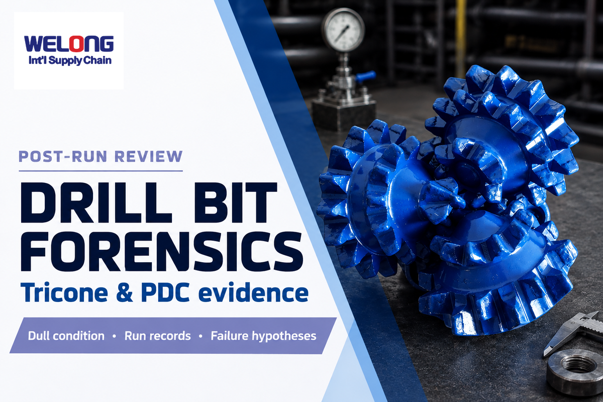
This document describes post-run evidence, dull condition review, failure hypotheses and what’s learned for the next run. The approved drilling program, controlled supplier documents and responsible engineering authority remain the major controls.
Drill bits (Tricone & PDC) should be reviewed based on field evidence rather than comparing a new design with an old one. A useful question to ask after a run is which dull condition, hydraulics, and operating response can help explain failure evidence and guide one controlled next-interval change.
Decision boundary: This guide describes dull evidence, damage location, synchronized run records, failure hypotheses, and next-run review. The existing Drill Bits (Tricone & PDC) solution page remains the owner for available design options, supply scope, customization, lead time, and quotation.
Don’t arrive at a root cause from a dull code or photo alone. The starting point is always six evidence signals and naming what’s unknown. Carry one documented hypothesis and contingency into the next run review.
That boundary is important because drill bits (Tricone & PDC) serve two different reader needs. A buyer needing products requires a configuration and supply discussion on the commercial page. A post-run reviewer in oil and gas needs a way to connect damage location, downhole dysfunction, hydraulics, dull condition, and time- and depth-aligned records.
The method below may conservatively cover types of drill bits in the drilling industry where tricone and PDC comparisons help diagnose the returned bit; it doesn’t provide universal weight on bit tables, state that one family always drills faster, or consider a certificate as evidence of field performance. Published data from lab and field tests are kept at test conditions. The named frameworks are tools for completeness of the record, and aren’t standards or guaranteed root-cause models.
Crushing, Chipping, and Shearing: Forensic Context for What the Rock Sees
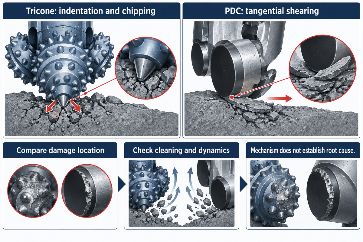
A tricone tooth creates a concentrated indentation and chips rock as the cones rotate. A PDC cutter, the diamond cutting element held in the bit body, removes rock by means of a tangential shear. The path of the energy and the means of survival are different, but failure also depends on confinement, rock abrasiveness and hardness, discontinuities, cleaning, heat, and dynamics of drillstring.
| Condition | Rock-removal response | Damage exposure | Record to inspect |
|---|---|---|---|
| Continuous, drillable interval | Sustained cutting may reward a fixed-cutter layout | Heat and wear can accumulate | ROP, torque, MSE, temperature context |
| Abrupt interbed | Depth of cut and contact force change quickly | Impact, chipping, and dynamic excitation | Depth-matched lithology and vibration |
| Fractured rock | Contacts alternate between support and release | Shock and uneven loading | Losses, torque, vibration, and dull location |
| Abrasive rock formation | Sharpness and gauge can erode over footage | Wear flats, broken inserts, gauge loss | Mineralogy, gauge measurements, photos |
| Cleaning-limited bottom | Cuttings interfere with fresh-rock contact | Recutting, heat, erosion, packing | Flow, pressure, nozzles, returns |
| High thermal exposure | Material and component response becomes design-specific | Seal, lubricant, bearing, braze, or cutter damage | Temperature estimate and component limits |
| High confinement | Force and chip formation can differ from ambient tests | Higher load for the same apparent depth of cut | Depth, pressure, stress model, and response |
| Stick-slip | Intermittent angular speed changes cutting depth | Torsional overload and cutter damage | Surface and downhole RPM plus torque |
| Whirl or lateral motion | Contacts move outside their intended path | Gauge and shoulder damage | Vibration mode, BHA, and damage location |
| Bit bounce | Repeated separation interrupts stable cutting | Axial impact and broken elements | Axial vibration, WOB, and lithology |
Sandia’s work on hard rock drilling reported that failure of PDC cutters can happen from impact before appreciable wear can be observed. This can be a good forensic warning. A bit can look new, and it may not have been worn significantly, but it can have experienced a dynamic event that damaged the bit.
Bit, BHA, formation and operational records have to be read in conjunction with one another.
A roller-cone mechanism, as found in roller cone bits, may be identified by three rotating cones, but this doesn’t identify the cause of failure.
A tricone bit and PDC drill bits may show damage in different locations across soft and hard formations; a review of PDC bits and tricone bits still has to test evidence rather than accept a bit-family label as the reason for failure.
Read the Returned Bit by Evidence Field, Not Family Ranking
This forensic comparison is done after a bit has been pulled. Each row poses what the returned tricone or PDC bit may reveal and which run record is needed to assign a cause. The columns don’t recommend a product family. They distinguish observable conditions from an explanation that must still prevail through the event timeline.
| Decision field | Tricone evidence to inspect | PDC evidence to inspect | Evidence still required |
|---|---|---|---|
| Rock-removal marks | Dented, chipped, worn, or lost teeth and inserts by cone position | Wear flats, chipped cutters, delamination, and damage by blade position | Depth-matched lithology, confinement assumptions, cuttings, and drilling response |
| Moving components | Cone rotation, bearing condition, seals, lubricant evidence, and shirttail wear | No rotating cones; inspect blades, cutter pockets, body, and connection instead | Bit serial, runtime, temperature context, repair history, and BHA condition |
| Cutting elements | Milled teeth or tungsten carbide inserts, including location and retention | Polycrystalline diamond compact cutters, including exposure, rake, and substrate condition | As-run design record, labeled photographs, scale, orientation, and event window |
| Impact signature | Broken inserts, cracked teeth, cone damage, and localized loading marks | Chipped or lost cutters, braze or pocket damage, and shoulder concentration | Transitions, fractures, shock, axial/lateral vibration, RPM, and torque by depth |
| Abrasive signature | Gauge, teeth, shirttail, cone shell, and bearing-area condition | Wear-flat progression, gauge loss, erosion, matrix or steel-body wear | Mineralogy, solids, cuttings, return condition, accepted footage, and comparable photographs |
| Interval continuity | Check whether damage changes between cones or near abrupt formation transitions | Check whether wear or impact clusters align with continuous or interrupted cutting | Depth-matched markers and event data, not a broad formation label |
| Cleaning signature | Packed cone areas, erosion, balling, recuttings, and nozzle condition | Blade loading, cutter cooling evidence, junk-slot packing, erosion, and recutting | Fluid properties, flow, pressure, nozzles, losses, solids, and returns |
| Directional loading | Uneven cone, gauge, or shirttail condition tied to side force and toolface response | Localized shoulder, gauge, blade, or cutter damage tied to lateral motion | Inclination, azimuth, dogleg, steerability record, BHA, and downhole vibration |
| Trip reason | State whether the bit, bearing system, another BHA component, or the plan ended the run | State whether cutter/body condition, another tool, or a field event ended the run | Daily report, accepted footage, residual condition, handling record, and event chronology |
| Inference limit | The family name and visible damage do not prove the initiating mechanism | The family name and visible damage do not prove the initiating mechanism | A competing hypothesis, confidence statement, contingency, and next-run discriminating evidence |
The 6-Signal Dull-to-Dysfunction Crosswalk
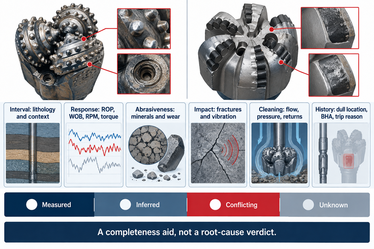
The 6-Signal Dull-to-Dysfunction Crosswalk is a post-run completeness method. It contextualizes interval behavior against drilling response, abrasiveness, and impact exposure, and evaluates cleaning margin and prior bit/BHA behavior against the observed dull condition. It doesn’t determine the cause, but shows which evidence is in conflict, what hypotheses of failure remain, and what should be tested next.
This differentiation is critical. The crosswalk isn’t an IADC method, probability model, or surrogate for responsible engineering. Its purpose is to prevent a team from hiding a missing variable behind a confident root cause claim. Each signal is classified as measured, inferred, conflicting, or unknown. “Unknown” is retained. It doesn’t become favorable evidence.
How should you investigate tricone or PDC damage when offset data are incomplete?
Select a working hypothesis, not a permanent verdict. State the best-supported failure mechanism, and name the unverified mechanism that could defeat it. Provide one alternative explanation. Describe the evidence that would allow you to switch hypotheses. Limit the first comparison to a reasonably comparable interval and avoid changing the bit, BHA, hydraulics, WOB, and RPM all at the same time. Otherwise, the drilling project produces footage, not reusable knowledge. One example of why chatter and impact evidence needs to be tied to the run is the Sandia hard-rock study.
| Signal / observation | Evidence | Tricone evidence to test | PDC evidence to test | Evidence or stop condition |
|---|---|---|---|---|
| 1A. Interval continuity | Depth-matched lithology and offset response | Check whether abrupt transitions align with damage | Check whether continuous cutting aligns with observed wear | Stop claim if offsets are not comparable |
| 1B. Thermal context | Expected downhole temperature and component limits | Verify bearing, seal, and lubricant envelope | Verify cutter, braze, substrate, body, and cooling | No generic temperature ceiling |
| 1C. Confining-stress context | Depth, pressure, stress model, laboratory boundary | Keep as a force and chip-formation modifier | Keep as a force and MSE modifier | Do not transfer ambient-test values directly |
| 2A. Strength and drilling response | ROP, WOB, RPM, torque, MSE by depth | Check tooth or insert engagement | Check depth-of-cut and efficient response region | Stop a WOB increase when response flattens or dysfunction rises |
| 3A. Abrasiveness | Mineralogy, cuttings, gauge and wear photos | Check teeth, shirttail, gauge, and bearing protection | Check cutter grade, gauge, body, and erosion exposure | Switch review if wear rate threatens accepted footage |
| 4A. Fractures and transitions | Markers, losses, shock, lateral and axial vibration | Check cone and tooth damage at transition depths | Check cutter damage against impact and dynamics records | Stop on repeated impact or localized cutter damage |
| 4B. Torsional dysfunction | Surface/downhole RPM and torque | Review cone contact and BHA interaction | Review stick-slip and depth-of-cut control | Do not blame formation from averages alone |
| 5A. Cleaning margin | Flow, pressure, nozzles, fluid, returns, losses | Check bottom and cone cleaning | Check junk slots, cutter cooling, and recutting | Stop parameter escalation when hydraulics limit response |
| 6A. Prior dull location | Labeled face, shoulder, gauge, cone, bearing photos | Connect tooth/bearing/gauge condition to the run | Connect cutter/body/gauge condition to the run | A code without photos is incomplete |
| 6B. BHA and trip reason | Assembly, drive system, events, why the bit was pulled | Separate bit limit from another tool’s limit | Separate bit limit from another tool’s limit | Do not call a BHA trip a bit failure |
IADC Codes and Dull Grades: Evidence, Not Root Cause
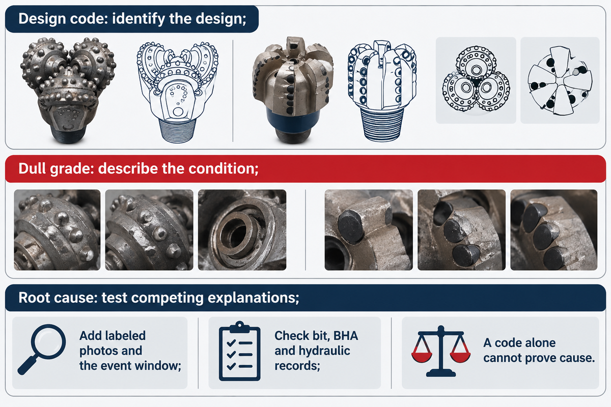
A pre-run IADC classification describes a design family, and a post-run dull grade describes a condition. Neither proves a single root cause, guarantees the next run, nor eliminates the need for pictures, synchronized formation, BHA, hydraulics, and operating data. State which grading practice and revision was utilized for the run.
What does IADC dull grading tell you about the next run?
Information shows where trained reviewers located damage on returned bits. The evidence doesn’t necessarily show the root cause of the damage. It can’t, by itself, distinguish among design, formation, WOB, RPM, cleaning, and directional demand. It can’t, by itself, distinguish among an unrelated trip, BHA dysfunction or a dysfunctional bit.
On April 9, 2026, the International Association of Drilling Contractors announced a new Bit and BHA Dull Grading Manual. Its public release joins drilling forensics, bit and BHA grading, failure reporting, visual information, and run-data management. That date should be recorded because a current manual and a legacy code aren’t interchangeable evidence systems.
Forensic reminder: “IADC dull grades are insufficient.”
| Observed record | It reports | It does not prove | Check next |
|---|---|---|---|
| Pre-run classification | A described design category | Performance in the next section | Detailed design and application basis |
| Inner cutting-structure wear | Condition and location | Abrasion as the only cause | Lithology, heat, loading, and images |
| Outer/gauge wear | Loss or damage near outer structure | A single directional or abrasive cause | Gauge measurements, side force, hole condition |
| Chipped or broken cutter/insert | Localized element damage | Whether shock, overload, flaw, or handling caused it | Damage map, vibration, transitions, handling record |
| Bearing failure | A failed or degraded bearing condition | Whether seal, heat, load, fluid, or runtime initiated it | Seal, lubricant, temperature, time, and load |
| Erosion | Material loss pattern | The responsible fluid path or solids mechanism | Nozzles, fluid, solids, pressure, and location |
| Lost component | A missing part or portion | Where it is or why retention failed | Recovery exposure, retention, debris, and event time |
| Pulled for a non-bit reason | The trip reason was not the bit | The bit had reached its life limit | BHA event, field decision, residual condition |
| Unlabeled photo | Only a visual appearance | Location, orientation, timing, or progression | Bit ID, face position, scale, angle, and depth context |
If a broken element may have remained downhole, the post-run team should document the exposure and route the recovery issue under the approved plan. The relevant commercial equipment is fishing and milling tools; this manual won’t describe a recovery operation.
Map Construction Clues Before Naming a Failure Cause
Construction details should be explained because they show the location of the evidence and not because they select a new bit. Each observation should include a labeled damage map and design revision, and serial number. The intended effect column describes the design function and doesn’t speculate that it created the field result.
| Construction field | Intended effect | Evidence to request | What can reverse the benefit |
|---|---|---|---|
| Cutting-structure identity | Establish the exact teeth, inserts, or cutter layout that entered the hole | Serial, revision, face map, element count, locations, and labeled photographs | Wrong revision, repair substitution, missing identity, or unlabeled damage |
| Cone, bearing, and seal system | Support roller-cone motion while retaining lubricant and excluding debris as designed | Cone freedom, bearing debris, seal condition, lubricant evidence, hours, and temperature | Heat, overload, contamination, loss of seal integrity, or unrelated handling damage |
| Body material and blade or cone support | Carry drilling loads and retain cutting elements in the as-built geometry | Steel or matrix record, erosion map, cracks, pockets, cone shell, and repair history | Impact, erosion, fatigue, manufacturing variance, or an unrecorded repair |
| Gauge and shoulder | Maintain hole size and manage outer-radius contact under the approved design | Before/after gauge measurements, wear location, side-force history, and hole condition | Whirl, abrasiveness, undergauge running, directional loading, or poor stabilization |
| Nozzles and flow passages | Deliver the hydraulic layout recorded for bottom cleaning and component cooling | Installed sizes, total flow area, orientation, plugging, erosion, pressure, and flow | Solids, losses, recirculation, damaged nozzles, or a configuration different from the record |
| Cutter, insert, braze, or retention interface | Transfer load while retaining the cutting element in its intended position | Fracture surface, pocket condition, missing material, neighboring damage, and event time | Shock, overload, heat, flaw, debris impact, or post-run handling |
| Thermal path | Keep seals, lubricant, cutters, braze, substrate, and body within controlled limits | Temperature estimate, cooling record, discoloration, material evidence, and exposure time | Poor cleaning, frictional heat, stalled motion, high ambient temperature, or model error |
| Erosion protection | Protect exposed body, nozzle, blade, shirttail, and gauge locations from the planned fluid path | Material map, erosion location, solids loading, fluid properties, and nozzle condition | A changed flow path, abrasive solids, cavitation, recutting, or damaged hardfacing |
| Connection and make-up record | Transfer torque and axial load through the documented interface | Connection identity, make-up record, shoulder condition, cracks, and handling chronology | Incorrect make-up, galling, misalignment, overload, or surface handling damage |
| Repair and reuse status | Preserve traceability of changes that could affect the returned condition | Prior inspection, repair scope, replaced parts, release record, and previous dull history | Incomplete traceability, mixed components, undocumented rework, or non-comparable prior service |
Scope Controls for Transferring Evidence Between Applications
Application and feature labels may describe a run, but none, by itself, should be considered the root cause. Maintain the as-run state, including subsurface geological conditions, when a lesson learned is transferred between drilling applications, bit families, formations, or industries.
Use the 7-Channel Operating Record for Time-Aligned Forensics
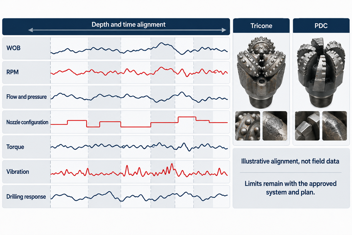
An operating record for the driller aligns seven channels by depth and time: WOB, RPM, flow and pressure, nozzle configuration, torque, vibration and drilling response. Limits come from the bit, BHA, drive system, hydraulics, formation and approved plan. An isolated average doesn’t explain why the response changed.
| Channel | Unit and source | Context retained | Response question | Limit owner |
|---|---|---|---|---|
| 1. Weight on bit | lbf or kN; surface and modeled/downhole | Depth, transfer loss, bit size | Did added load create useful cutting? | Bit/BHA/drive approved envelope |
| 2. Rotary speed | rpm; surface and downhole | Motor/RSS contribution, stick-slip | Was cutter speed stable? | Bit, motor, rotary system |
| 3. Flow and pressure | gpm or L/s; psi or MPa | Mud, depth, losses, solids | Was cleaning margin maintained? | Hydraulic program and equipment limits |
| 4. Nozzle configuration | Count, size, total flow area | Installed serial and change history | Did the pressure response match the plan? | Approved bit and hydraulic design |
| 5. Torque | lbf·ft or kN·m; surface/downhole | Depth, RPM, lithology, filtering | Did cutting load or torsional dysfunction change? | Rig, BHA, connection, and bit limits |
| 6. Vibration | Mode-specific sensor record | Location, sample rate, time alignment | Was impact, whirl, bounce, or stick-slip present? | Tool and operating procedure |
| 7. Drilling response | ROP, MSE, cuttings, returns | Accepted footage and formation markers | Did the change improve useful work without damage? | Drilling program and decision owner |
An approved change to a single input is made in defined steps. During the change, other inputs are observed. The outcome is noted and can be a positive or negative response. A rise in surface ROP is not enough if downhole vibration rises, torque becomes unstable, or pressure behavior changes. Cuttings can also indicate recirculation. Directional drilling adds toolface response and steerability to the review. Stop signals and final limits belong in the drilling operations program.
There are other factors beyond the bit that can shape the forensic record. The motor, rotary steerable systems, drill collars, jars, subs and measurement while drilling (MWD) tools can all impact the forensic record. The entire configuration of downhole drilling tools in the recorded assembly should be evaluated to understand how bit damage can be attributed to BHA interaction and how it influences the overall well trajectory; surface trip and handling records should also be evaluated prior to determining downhole damage.
Pipe handling tools should also be considered when evaluating the surface trip and handling chronology.
Close the Loop from Dull Condition to the Next Bit Run
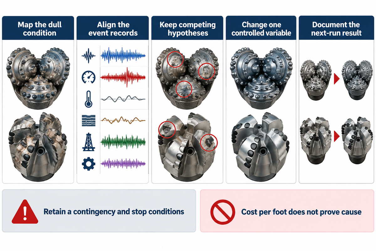
This review aid links eight record groups for a next-run decision: bit identity, bit interval and formation; planned vs. actual operations; hydraulics, BHA and drive system; time-aligned dysfunctions; dull photos and grading; accepted footage with trip reason. Change one controlled variable to produce reusable evidence in the next run, if feasible.
A dull photo doesn’t end an investigation. The ExxonMobil forensics material connects surface drilling data and bit images to possible dysfunction such as stick-slip, whirl, bit bounce, and overload in heterogeneous formations. The analyst still needs time and depth alignment of the recorded drilling conditions. A damage mark without the associated event window is weak evidence.
- Lock identity: record bit serial number, size, connection, family, design revision, repair status, nozzles and installed configuration.
- Define the interval: mark tops and bottoms, lithology, fracture, loss zones, temperatures and in-situ assumptions.
- Preserve the plan – retain the approved WOB, RPM, hydraulic, directional and stop-condition plans.
- Align actual channels – time and depth synchronize surface and downhole records; maintain sample rate and positions of sensors.
- Map dull condition, photograph face, shoulder, gauges, cutting elements, cones, bearings and other pertinent body parts, indicating scale, label and orientation.
- Separate observation from inference – define each inference that explains the observation and the evidence that might help resolve the inference.
- Explain the trip – state why assembly was pulled; state why run ended (because of bit, other BHA component, plan, field event).
- Approve one learning change – specify the changed variable, the predicted response, the owner and the evidence to be collected; define the state of affairs that will cause the change to end.
In conjunction, the seven-channel operating record and eight-stage next-run loop provide means to connect operating data with dull condition, and to do so without invoking first-party field performance data. The numbered sequence is a review aid, not a claim that every failure path will have eight causes, or that the method provides a measured prediction rate.
Following a series of bad runs, several teams consider changing almost everything. While it’s tempting to want to change everything, keep in mind that changing everything makes it impossible to know the cause of an improvement, or gives no attribution. Let’s say a team changes their bit from tricone to PDC, changes motor bend, increases flow, changes nozzle area, increases WOB, and increases rotary speed. If the run improves, no one is able to say which adjustment made the run better. If the run is still poor, no one is able to say which adjustment caused the issue. At least the adjustment should be clear to everyone.
A supplier-authored field case by Alexis Garcia of National Oilwell Varco in Drilling Contractor records footage, average rate, lithology, bit design, and two BHA-related trips. The lesson isn’t the reported performance number. The lesson is that trip reason belongs with footage; otherwise, another tool’s limit can be assigned to the bit design.
Why Cost per Foot Cannot Prove a Failure Cause
All values below are deliberately hypothetical. This isn’t a current estimate, a China Welong field-performance claim, or a recommendation for a particular bit.
| Input | Hypothetical value | Replace with | Sensitivity |
|---|---|---|---|
| PDC bit cost | $45,000 | Comparable approved quote | Changes the numerator but does not identify a physical cause |
| Rig time rate | $1,500/h | Project time-dependent rate | Magnifies time difference and trip exposure |
| PDC success footage | 3,600 ft in 60 hours | Comparable accepted footage | Strong denominator effect; retain interval comparability |
| PDC rotating time | 60 hours | Time-aligned field record | Affected by response, dysfunction, and non-bit limits |
| Normal trip time | 20 hours | Well-plan estimate | Applies once per scenario; record the actual trip reason |
| Premature-event footage | 900 ft after 24 hours | Failure-mode event tree | Dominant denominator risk and a trigger for forensic review |
| Premature-event consequence | $25,000 | Non-time event cost only | Must not duplicate trip hours or invent a cause |
While a cost result can signal where a post-run analysis should be directed, it can’t distinguish between wear, impact, and/or cleaning loss, as well as malfunction of other BHA components or a trip caused by another component. Keep the cost scenario downstream of the dull review. If the likelihood of an event occurring, or the potential consequence of the event lacks comparable evidence, mark the situation as judgment and don’t create a product family recommendation.
The 7-Record Post-Run Evidence Dossier
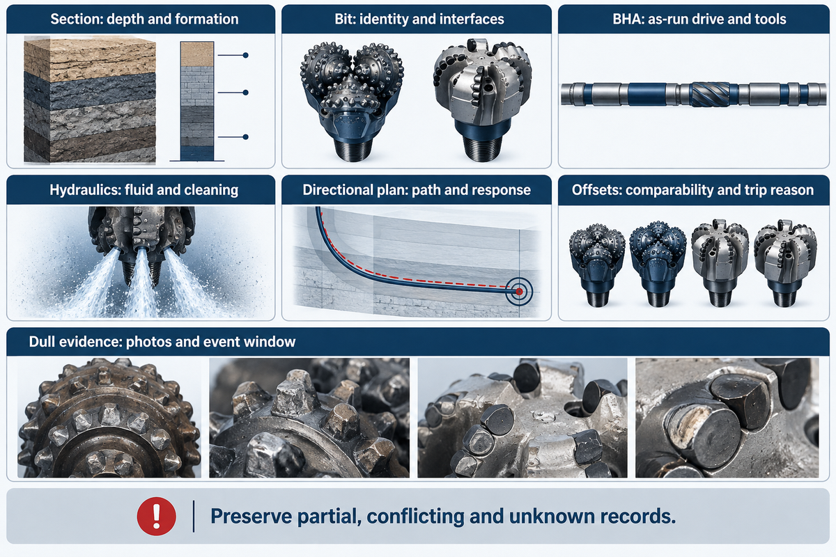
The section and formation, bits and interfaces, BHA and drive, hydraulics and drilling fluids, directional plan, offset performance, and dull/failure data are included in the 7-Record Post-Run Evidence Dossier. Each piece of data is identified as measured, estimated, conflicting or unknown. Reviewers can use these inputs to formulate competing failure hypotheses.
| Record | Minimum contents | Status field | Decision consequence if missing |
|---|---|---|---|
| 1. Section and formation | Hole size, depth, interval, lithology, continuity, abrasiveness, fractures, temperature and stress context | Measured / inferred / unknown | Cutting structure and risk premise differ |
| 2. Bit and interface | Size, connection, gauge need, nozzles, prior design, repair status, required records | Controlled / provisional / unknown | Damage cannot be tied to the exact as-run configuration |
| 3. BHA and drive | Motor/RSS/rotary, bend, stabilizers, collars, jars, tools, limits and dynamics history | As-run / planned / unknown | Steerability and loading assumptions change |
| 4. Hydraulics and fluid | Mud properties, flow, pressure, nozzle area, solids, losses, cuttings and temperature | Measured / modeled / unknown | Cleaning and erosion exposure cannot be compared |
| 5. Directional plan | Inclination, azimuth, build/turn need, dogleg target, toolface response and hole-quality need | Approved / draft / unknown | Directional loading cannot be separated from bit interaction |
| 6. Offset performance | Comparable depth, design, WOB, RPM, flow, ROP, footage, hours, trip reason and cost basis | Comparable / partial / not comparable | The comparison may mix unlike intervals or trip reasons |
| 7. Dull and failure evidence | Grade revision, labeled photos, damage map, event window, vibration, BHA condition and competing causes | Complete / partial / absent | The next design may repeat an unidentified failure route |
An estimated temperature provides some evidence if the uncertainty and source are captured. A copied offset ROP is weak evidence if depth, lithology, BHA, and trip reason are missing. Reviewers should state which assumptions materially affect a failure hypothesis and the next controlled change.
Once the dossier is complete, use the existing Drill Bits (Tricone & PDC) solution page for available product design options, customization, supply scope, lead time, and quotation. China Welong states that it was founded in 2001 and operates as an international integrated supply-chain service provider; its background remains on the About Us page, commercial inquiries remain on the solution or contact page, and this guide stops at post-run evidence instead of duplicating the commercial selection brief.
Frequently Asked Questions
- What can an IADC dull grade prove?
- It records observed condition and location under a stated grading practice. It does not prove a single root cause without photographs and synchronized formation, BHA, hydraulic, and operating evidence.
- Can a PDC cutter fail before obvious wear appears?
- Yes. Sandia reported impact-related PDC cutter failure before appreciable wear was visible, so a new-looking surface does not exclude a damaging dynamic event.
- Why must records be aligned by depth and time?
- Alignment lets reviewers test whether vibration, torque, pressure, lithology, and damage location belong to the same event window rather than to unrelated parts of the run.
- What should change on the next controlled run?
- Where practical, change one owned variable, state the predicted response, retain a contingency, and define the evidence and stop condition before the run.
- Does an ISO 9001:2015 or API 7-1 statement explain a drill-bit failure?
- No. Verify the exact legal entity, site, current scope, design-family controls, offered-item evidence, and order record; none of those alone proves the field cause or outcome.
Turn the Dull Review into a One-Page Next-Run Record
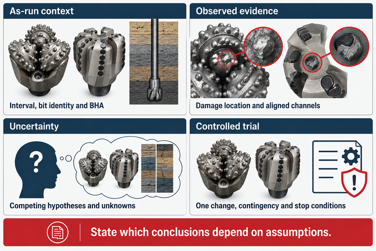
To choose the right next controlled trial, write a one-page review record before asking for a new winner. Cite the interval, as-run bit identity, observed damage, evidence confidence, BHA, seven operating channels, competing failure hypotheses, contingency, and stop conditions. Attach the seven-record post-run dossier and retain the surface-data and dull-image evidence used to test failure hypotheses. Then state where each conclusion depends on an assumption rather than a measured input.
- There are many factors that may be unknown. For example, factors such as temperature or vibration may be uncertain. There may be unknown offset comparability. There may be uncertainty about the dull condition. These uncertainties should be considered in the decision.
- A universal operating table shouldn’t be copied. The approved limit owner is the bit/BHA/hydraulic system and drilling program.
- Don’t change six variables and call the next run a test. Retain attribution if operations allow.
This may result in a controlled tricone trial, a PDC trial or a hybrid of the two. The main thing is each change should test a documented failure hypothesis and be attributed for the next dull round review.
References & Sources
- Sandia National Laboratories, historical PDC testing and high-temperature component context.
- Published petroleum engineering paper, bit cost-per-foot variable structure and case data.
- ASME Journal of Energy Resources Technology, hybrid drill-bit design and bounded application case.
- OnePetro, hard, abrasive, and heterogeneous formation performance boundaries.
- Google Patents: hybrid drill-bit construction context, here.
- The Innovation Energy, review of PDC cutter and bit research, 2026.
- U.S. Department of Energy / Sandia technical paper, PDC rate-of-penetration modeling and bounded laboratory/field verification.
- Sandia National Laboratories, testing/chatter related impact exposure.
- Rock Mechanics and Rock Engineering, primary experiment on confining pressure and rock cutting response.
- International Association of Drilling Contractors, release of the 2026 Bit and BHA Dull Grading Manual.
- ExxonMobil material hosted by Drilling Contractor, Bit and BHA Forensics evidence requirements.
- Drilling Contractor, Alexis Garcia, National Oilwell Varco: supplier-authored hybrid field case.
- American Petroleum Institute, official API programme product scope resource.
Why Buyers Work With Welong
About Welong Engineering Support
China Welong supports oilfield buyers with engineered supply-chain service for drilling tools, well-control equipment, rig-floor tools, casting parts, and industrial forged components.
Project Review Before RFQ
We help buyers compare tool family, material route, API or ISO requirements, inspection records, supplier capability, delivery risk, and documentation needs before a purchase decision is finalized.
Request An Oilfield QuoteCompany Profile // Data Sheet
CompanyChina Welong International Supply Chain
BrandWelong
CountryChina
Business TypeOilfield tools and industrial supply-chain partner
Main ProductsDownhole drilling tools, fishing and milling tools, wellhead and well-control equipment, oilfield hoses, rig-floor handling tools, mill rolls, and forgings
Engineering CapabilityTool-family selection, specification envelope review, API / ISO reference support, material traceability, inspection coordination, and supplier-route comparison
RFQ Data NeededTool type, size, connection, rating, grade, standard, quantity, drawings, and delivery target
Websitewelongoiltools.com