Get in touch with Welong Company

Updated October 2026
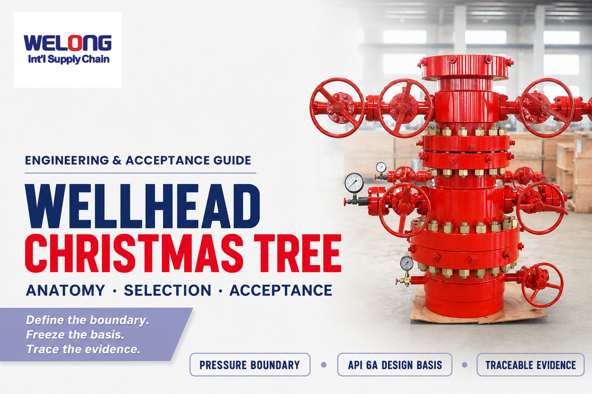
A Wellhead Christmas Tree system spans two connected but distinct assemblies. A wellhead, installed at the surface, supports and seals both casing and tubing. A Christmas tree is the valve-and-choke assembly installed above it after completion to isolate, route and regulate production, injection and intervention paths. Selection does not follow pressure alone. Rather, it follows the well design, fluid, temperature, interfaces, project philosophy and purchase specification.
A production Christmas tree is an assembly of valves and other equipment used to control the flow of oil and gas from the well during production. In oil and gas industry language, Christmas tree systems are also called Xmas tree systems. This piece of equipment belongs to the completed-well system, not to the drilling stack.
Wellhead and Christmas tree equipment are separate pieces of equipment: the wellhead sits below, and the tree is installed on top of the wellhead after completion. This boundary applies to an oil well, a gas well, or another oil or gas well; it also spans drilling and production equipment without making those systems interchangeable. A christmas tree during drilling operations isn’t the regular order. Drilling operations use different well-control equipment, and the tree, attached to the wellhead, is only installed after completion.
The buyer’s short version
The pressure boundary is first defined, and the design basis is then frozen. Require each delivered record to trace back to the exact component. An “API 6A” statement is a starting point, not proof of the legal manufacturer, facility, licensed scope or item-level acceptance package.
Wellhead vs. Christmas Tree: Where the Pressure Boundary Changes
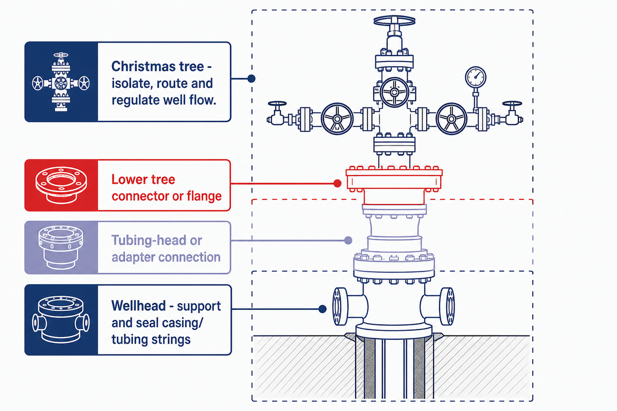
At the lower boundary, the wellhead carries and seals the casing and tubing interfaces; above it, the Christmas tree controls the completed well’s accessible flow paths. This demarcation shows a buyer which drawing, flange, or connector, pressure boundary and record pertains to which assembly. It also prevents a tree quotation from quietly assuming an unresolved wellhead interface.
Functionally, the wellhead and Christmas tree are entirely separate even though they connect physically. Integrated wellhead systems can physically share interfaces, but remain functionally distinct.
Wellhead equipment drawings should show the mating boundary. A christmas tree is installed only after completion interfaces are confirmed, and the christmas tree’s primary duty remains flow path control.
The primary function of a tree is to control flow and well intervention access during production; in a gas injection well, it may instead control the injection of gas. Depending on the service, a wellhead may support a gas injection tree or an oil production tree, but the christmas tree and wellhead should still be documented separately.
| Question | Wellhead | Christmas tree |
|---|---|---|
| Primary duty | Support and seal casing/tubing strings | Isolate, route and regulate well flow |
| Key interface | Tubing-head or adapter connection | Lower tree connector or flange |
| Typical records | Casing/tubing load and seal-interface records | Valve, choke, actuator, test and release records |
| Buyer check | Confirm the casing and tubing head interface | Confirm every flow path and its isolation philosophy |
Why Is It Called a Christmas Tree?
This name is derived from the branching nature of assembled valves, outlets, fittings and gauges. A conventional surface tree, when viewed from the side, resembles a decorated tree. However, this name doesn’t represent a single tree layout. Compact-block, dual-string, injection, dry-tree and subsea tree arrangements, for example, serve the same basic function of production control, but can vary considerably in appearance.
The Pressure-Boundary Handoff Map: Follow Each Flow Path
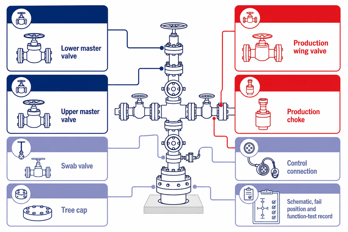
A component list becomes useful only when every item is tied to a flow path, isolation duty, adjacent interface and acceptance record. Below, the Pressure-Boundary Handoff Map serves as a buyer-side synthesis, not an API clause. Its purpose is to expose missing interfaces before they become assumptions in a drawing or quotation.
A surface layout may use a series of valves. If a gate valve design is chosen, the upper and lower master valves are still separate isolation duties. Some simplified diagrams show a total of five valves; treat five valves as one example, not a rule for every set of christmas tree components.
Tree complexity has increased as actuation and sensing are added. An actuator or monitoring system attached to the tree controls only the function shown on the approved schematic. When the tree acts as an attachment point for control lines, the tree acts within a named interface responsibility. Below the tree, the wellhead supports the Christmas tree and provides the pressure-boundary interface.
| Component | Path | Isolation or control duty | Adjacent interface | Evidence to trace |
|---|---|---|---|---|
| Tubing-head interface | Tubing bore / annulus | Transfers the completed-well boundary into the tree | Tree adapter, flange or connector | Approved interface drawing and seal details |
| Lower master valve | Main vertical bore | Primary lower isolation in a two-master arrangement | Tubing head below; upper master above | Valve identity, pressure and functional record |
| Upper master valve | Main vertical bore | Second vertical-bore isolation point | Lower master and cross/wing body | Serial-linked test and actuator data |
| Production wing valve | Production outlet | Opens or isolates the route to downstream production equipment | Choke or flowline spool | Flow-direction, trim and end-connection records |
| Production choke | Production outlet | Regulates flow and pressure drop | Wing valve and flowline | Trim identity, operating envelope and inspection baseline |
| Kill wing valve | Kill / injection route | Isolates a controlled pumping or circulation connection | Project-specified external line | Connection rating, valve record and line responsibility |
| Swab valve | Vertical intervention access | Isolates access above the main bore | Tree cap or intervention equipment | Bore, connection and functional record |
| Tree cap | Top access | Closes and protects the upper access interface | Swab valve / intervention adapter | Seal, locking and pressure-boundary evidence |
| Annulus outlet | Tubing-casing annulus | Provides a defined monitoring or service connection | Wellhead annulus passage | Port map, valve identity and monitoring basis |
| Control connection | Hydraulic/electric control | Transmits commands or status to actuated functions | Actuator, panel or downhole-safety-valve line | Schematic, fail position and function-test record |
Which Valves Control Each Wellhead Christmas Tree Flow Path?
Master valves isolate the main vertical bore, the production wing valve opens the route to the choke and flowline, the kill wing valve isolates a pumping or circulation route, and the swab valve controls access from above. Actual names and fail positions must be crosschecked against the approved schematic; a familiar label isn’t proof of the delivered flow path.
A drawing labeled “christmas tree or wellhead” still needs the boundary defined. Its range of Christmas tree valves depends on service, access and control philosophy rather than on the nickname alone.
Field perspective: Adrian Croft’s practical warning is that sand service is managed through valve, trim and operating choices; it is not made erosion-proof.
Paraphrased from Valve Magazine.
What API 6A Covers, and What “API Compliant” Does Not Prove
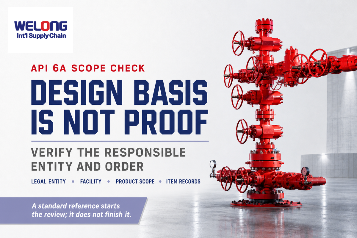
While API Spec 6A defines standards for wellhead and tree equipment, it doesn’t mean a vendor statement is proof that the named legal entity, manufacturing facility and scope of product have a current API Monogram license. Those are separate verifications.
| Statement or record | What it can establish | What still needs proof |
|---|---|---|
| “Designed to API 6A” | Declared design basis | Edition, designation, validation and order-specific conformity |
| API Monogram claim | Potential licensed-program participation | Current legal entity, facility and listed product scope |
| Item marking | Identity carried on the equipment | Match to data book, purchase order and directory entry |
| Certificate bundle | Documents were supplied | Traceability to the exact serialized item and approved design |
Consult the current API directory and tie it to the statement of work and order. Related wellhead and well-control equipment may involve other API specifications; a single standard label should never be applied to disparate equipment.
How to Translate Well Data into an API 6A Tree Design Basis
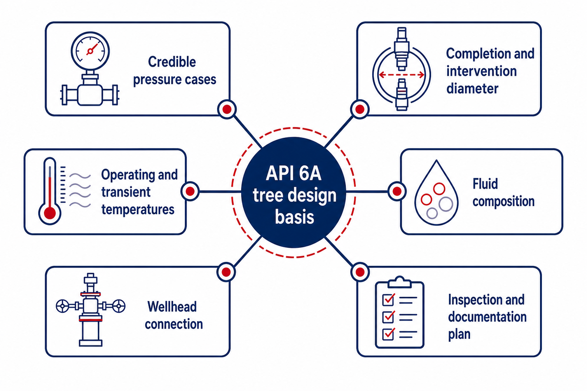
For surface trees, evaluation starts with credible service cases and completion interfaces, not a catalog model. Working pressure, bore, temperature, fluids, materials, product specification level, performance requirement and connections interact. A change in one input can alter the design, qualification, inspection, and/or documentation of the equipment.
Rates and volumes of gas shouldn’t be interpreted as tree ratings. Natural gas composition, liquid loading and solids exposure belong in the service description so the supplier can separate process duty from the equipment’s rated limits.
| Design input | Decision it drives | Evidence expected |
|---|---|---|
| Credible pressure cases | Minimum required rated working pressure | Approved design basis and pressure schedule |
| Completion and intervention diameter | Full-bore and restriction requirements | Completion schematic and dimensional interface sheet |
| Operating and transient temperatures | Temperature class, seals and operating limits | Temperature envelope and material/seal qualification |
| Fluid composition | Material and corrosion review | Fluid analysis and stated design assumptions |
| Solids and erosion exposure | Choke/trim choice and inspection baseline | Erosion review and replaceable-trim details |
| Wellhead connection | Lower tree interface and seal system | Approved interface-control drawing |
| Flowline and external connections | Wing outlets, orientation and rating compatibility | General arrangement and mating-component schedule |
| Operating philosophy | Manual/actuated functions, fail positions and controls | Cause-and-effect or functional schematic |
| Qualification designation | Product specification and performance requirements | Qualification matrix tied to the selected design |
| Inspection and documentation plan | Hold/witness points and release criteria | Approved inspection plan and data-book index |
How Should Working Pressure and Bore Size Be Selected for an API 6A Surface Tree?
Select rated working pressure from the governing credible pressure cases plus the project’s design rules, then select bore from the completion, production and intervention envelope. Do not uprate a weak interface by pairing it with a higher-rated component. A supplier’s published maximum shouldn’t be taken as a universal selection target.
Conventional, Compact-Block, or Subsea: Set the Configuration Boundary First
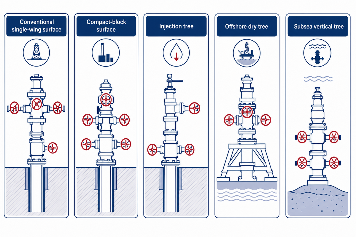
Tree family depends on the installation location, access, interface count, intervention path and control architecture. Working pressure alone doesn’t pick it. Below, nine contexts establish boundaries without replacing the project specification or engineering review.
Possible christmas tree configurations include surface and subsea christmas tree architectures, but the project must decide which standard applies. For gas and oil production, a production tree may be optimized for outflow. In an injection of gas or water duty, the configuration must instead be reviewed as a gas or water injection application.
A tree can operate on a non-producing well in order to support test, suspension, storage or injection service. Some storage wells produce and receive oil or receive oil or gas, so bidirectional service cannot be inferred from a typical production schematic.
| Tree type / context | Useful when | Boundary to resolve | Do not assume |
|---|---|---|---|
| Conventional single-wing surface | One primary production route is sufficient | Outlet orientation and maintenance access | A second route can be added without redesign |
| Conventional dual-wing surface | Production and kill/injection duties need distinct outlets | Line ownership and simultaneous-operation philosophy | Both wings have identical trim and duty |
| Dual-string surface | Two tubing strings require separate controlled paths | Bore identity, crossover risk and intervention access | A single-string schematic is adequate |
| Compact-block surface | Reduced interfaces or footprint are project priorities | Repair, replacement and internal passage visibility | Fewer external joints means lower total lifecycle risk |
| Injection tree | Normal well duty is controlled injection | Reverse flow, fluid compatibility and monitoring | Production-tree trim is automatically suitable |
| Test / workover tree | Temporary intervention or test duty governs | Temporary equipment interfaces and operating procedures | Permanent production acceptance covers temporary duty |
| Offshore dry tree | Accessibility remains above water | Platform motion, access and riser/wellhead relationship | Onshore maintenance assumptions transfer unchanged |
| Subsea vertical tree | Vertical access and project architecture favor the valve block above the tubing hanger | Installation sequence, controls and intervention route | API 6A alone defines the complete subsea basis |
| Subsea horizontal tree | Tubing-hanger access and workover philosophy favor a side-valve architecture | Tubing hanger, control module and recovery sequence | “Horizontal” means one standardized layout |
In a cited United States Outer Continental Shelf rule, API Spec 6A or API Spec 17D applies “as applicable.” That jurisdiction-specific wording is a useful warning: keep detailed API 6A selection here limited to the surface-tree context and resolve subsea standards separately.
Sour Service and Material Selection: Keep Two Standards in Their Lanes
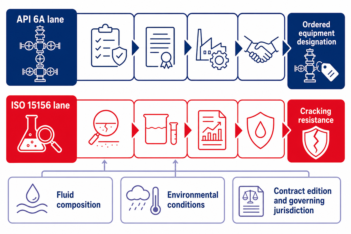
API 6A material designation and ISO 15156 qualification answer related but different questions. A material-class letter is not a complete sour-service conclusion. Other factors such as fluid composition, exposure to hydrogen sulfide, process conditions, chlorides, environmental conditions, material condition, and stress state of the component must also be assessed.
Chemicals or alcohols or oil-based carriers may be used for injection duty. Alcohols or oil distillates shouldn’t be assumed to be compatible with the seals; fluid compatibility must be assessed with respect to the actual material condition and operating envelope.
API 6A lane
Define the ordered equipment designation, product requirements, qualification and records for the applicable tree components.
ISO 15156 lane
Evaluate materials for cracking resistance in hydrogen-sulfide-containing oil and gas production environments.
ISO 15156 is a three-part family: Part 1 covers general principles, Part 2 covers carbon and low-alloy steels, and Part 3 covers corrosion-resistant and other alloys. Official pages list the 2020 fourth editions as published while also showing replacement work in progress. Meanwhile, a regulator may incorporate a different edition for named provisions. It is good practice to freeze the contract edition and governing jurisdiction rather than state only “latest.”
The Tree Acceptance Thread: Evidence That Must Survive the Purchase Order
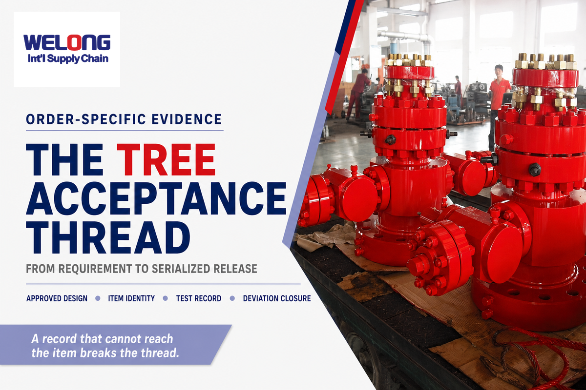
Acceptance isn’t the presence of a thick certificate bundle. Acceptance is an unbroken thread linking the purchase requirement, approved design, actual component, inspection and test record, deviation closure and release. This Tree Acceptance Thread stops whenever a record cannot be matched to the delivered serialized item.
| Link | Identity key | Evidence | Stop if missing |
|---|---|---|---|
| Purchase specification | PO and data-sheet revision | Approved technical requirements | No frozen acceptance basis |
| Approved design | Drawing and calculation revision | Approved general arrangement and interfaces | Delivered geometry cannot be reconciled |
| Bill of materials | Item and part number | Component-level material schedule | Critical parts are not identified |
| Material traceability | Heat/lot and part identity | Material test reports and transfer record | Heat cannot be traced to the component |
| Special processes | Part and procedure reference | Qualified welding, heat-treatment or coating records | Procedure/personnel status is unclear |
| Examination | Part, area and report number | Specified nondestructive-examination result | Acceptance criteria or coverage is missing |
| Pressure test | Serial number and test record | Approved procedure, calibrated instrument and chart/data | Item or instrument cannot be identified |
| Functional test | Valve/actuator tag | Stroke, position or control-function result | Fail position or acceptance result is absent |
| Deviation closure | Nonconformance number | Disposition, approval and reinspection | Open or unapproved deviation remains |
| Release and data book | Final serial and document index | Release note plus indexed final records | Final equipment and records do not match |
As mentioned in the applicable specification and purchase order, detail witness points, hold points, test procedure details, and acceptance limits. API’s official 6A update notice describes changes to records control, pressure-boundary qualification, design validation and factory-acceptance organization; it should not be misread as eliminating project-specific acceptance testing.
How to Verify the Responsible Manufacturer and API 6A Scope
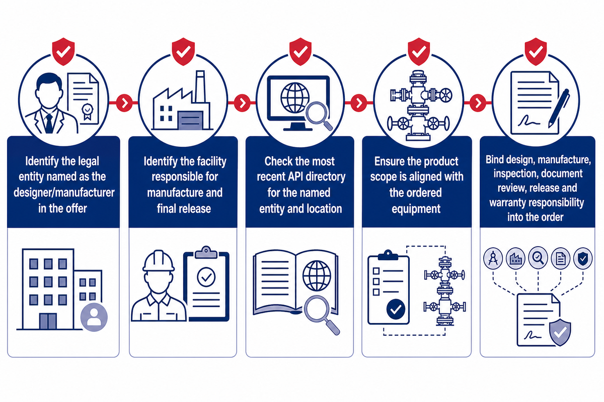
Verify the party carrying design and manufacturing responsibility, as opposed to the party whose name appears on the offer. A current API directory check should match the legal entity, physical facility and listed product scope to the order. A distributor or supply-chain integrator can coordinate the purchase, but that role is not interchangeable with licence-holder status.
- Identify the legal entity named as the designer/manufacturer in the offer.
- Identify the facility responsible for manufacture and final release.
- Check the most recent API directory for the named entity and location.
- Ensure the product scope is in-line with the ordered equipment rather than a general company description.
- Bind design, manufacture, inspection, document review, release and warranty responsibility into the order.
How Can a Buyer Verify an API 6A Manufacturer and Product Scope?
Use the official API Composite List or directory at the time of the purchase, and record the legal entity and facility shown there. Compare the scope of the licensed product with the exact tree components shown on the purchase order. Then request the quotation to identify who designs, manufactures, inspects and releases each component. A logo, a brochure or a generic statement “API Compliant” isn’t a directory match.
China Welong says that it’s an international integrated supply chain service provider. It states that the name of the responsible designer/manufacturer and the applicable requirements will be provided in the quotation. This is the correct location to preserve role clarity. It isn’t presented here as proof of a China Welong API 6A licence. See China Welong’s Supply-chain and Inspection Role.
Monitoring and Compact Integration Trends: What Changes for the Buyer?
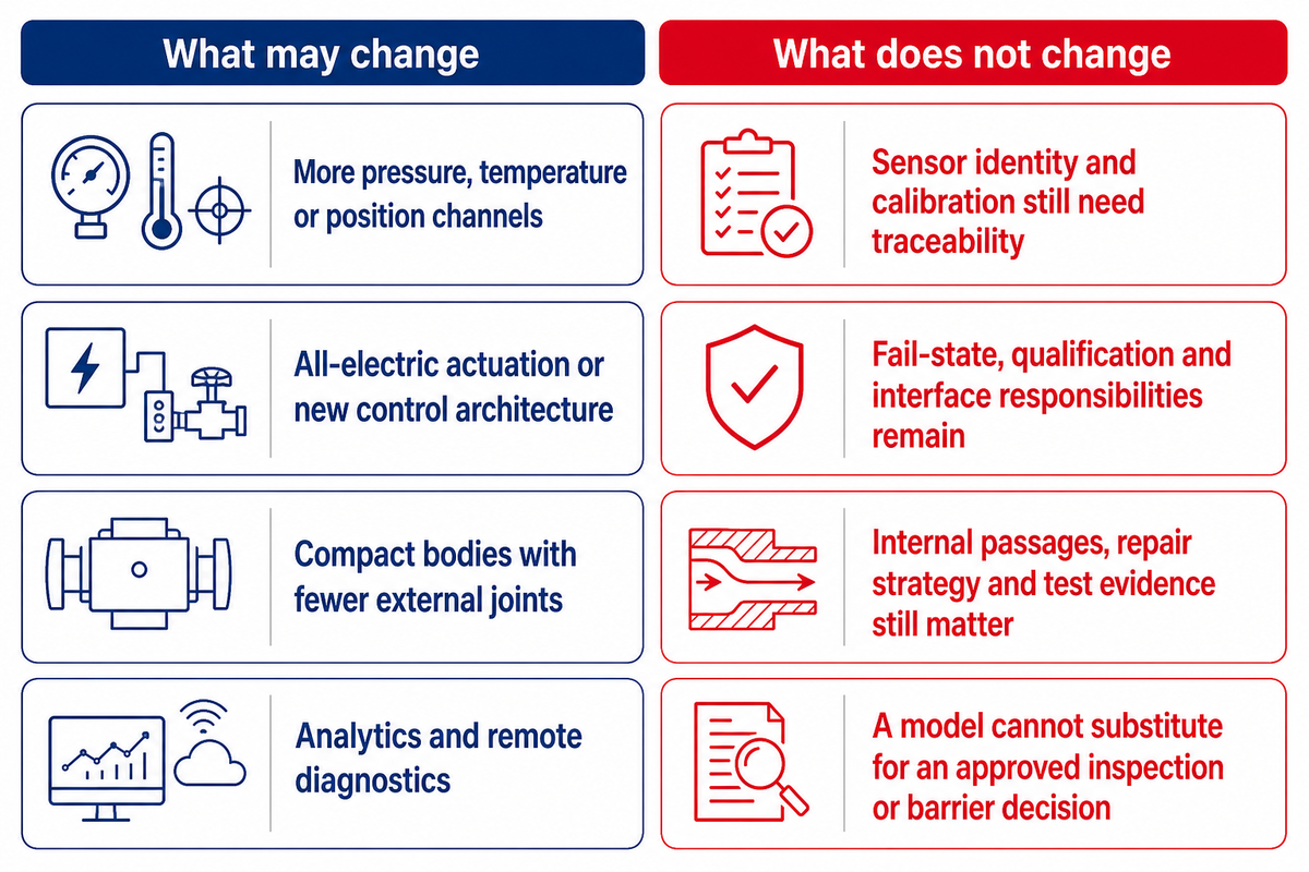
Both these trends maintain the mechanical design basis, the component identity and the acceptance thread. Customers get new questions on sensors and controls as well as the thermal behavior, diagnostics, and ownership of the data alongside the traditional questions on the integrity of the pressure boundary.
Through drilling and production, various digital functions transform how evidence is collected; who owns each interface remains the same. Each component of the system that’s approved and included in a Christmas tree must be identified, whether the control system is local, remote, hydraulic or electric.
| What may change | What does not change |
|---|---|
| More pressure, temperature or position channels | Sensor identity and calibration still need traceability |
| All-electric actuation or new control architecture | Fail-state, qualification and interface responsibilities remain |
| Compact bodies with fewer external joints | Internal passages, repair strategy and test evidence still matter |
| Analytics and remote diagnostics | A model cannot substitute for an approved inspection or barrier decision |
A 2001 compact horizontal tree patent and a 2023 monitoring patent demonstrate that the ideas have a technical lineage and didn’t appear suddenly. A peer-reviewed sensor study identifies thermal-management, hydrate, and cooldown trade-offs. No defensible adoption percentage was found; therefore, none is claimed here.
Maintenance and Troubleshooting Boundaries
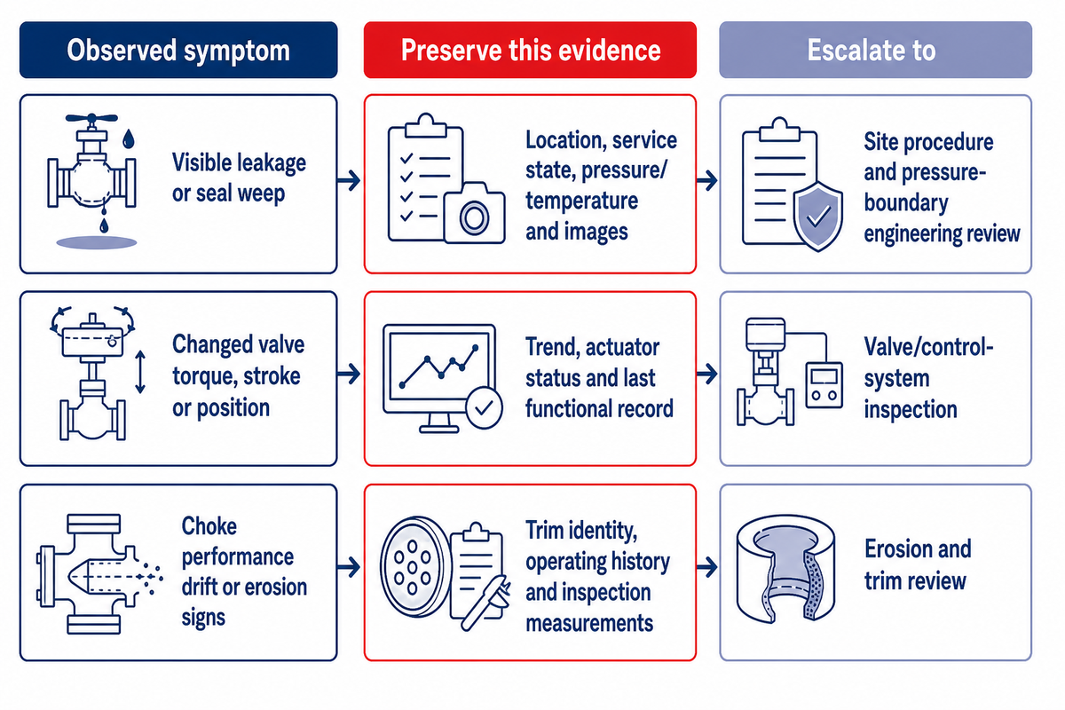
Tree inspections should uncover changes to the equipment and/or evidence and prompt an operating and/or engineering review. It should not turn a general article into a site emergency procedure. There’s no whole-tree service interval that can be extrapolated from tree erosion, leakage, or one jurisdiction’s component testing schedule.
| Observed symptom | Preserve this evidence | Escalate to |
|---|---|---|
| Visible leakage or seal weep | Location, service state, pressure/temperature and images | Site procedure and pressure-boundary engineering review |
| Changed valve torque, stroke or position | Trend, actuator status and last functional record | Valve/control-system inspection |
| Choke performance drift or erosion signs | Trim identity, operating history and inspection measurements | Erosion and trim review |
| Pressure or temperature anomaly | Raw signal, calibration state and correlated process data | Instrumentation plus well/production engineering |
| Damaged connection or exposed interface | Dimensions, condition, handling history and mating-part identity | Interface owner before reconnection |
For covered United States Outer Continental Shelf equipment, current federal rules include component-specific safety-valve test schedules and require two independent barriers before removing a tree or well-control equipment. For BOPs, use the broader well-control discipline guide.
Build the RFQ Around the Design Basis, Then Hand Off to the Product Page
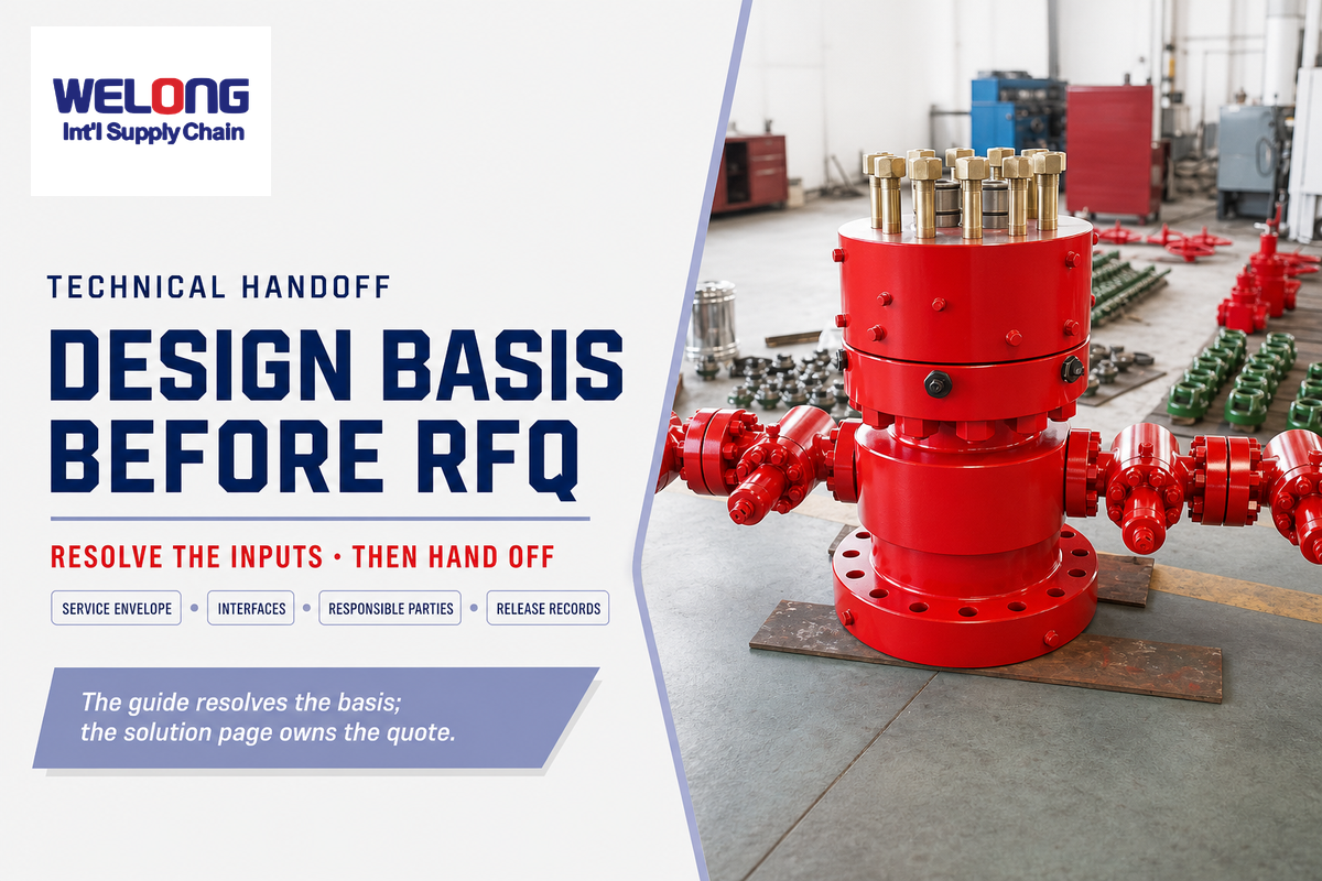
A useful Request For Proposal (RFQ) resolves the well and interface questions and provides a realistic set of constraints prior to asking a potential supplier to make equipment configuration decisions. At minimum, give the credible pressure and temperature cases, completion bore, fluids, installation environment, mating interfaces, operating philosophy, qualification basis, inspection scope and required document package.
| RFQ requirement | Buyer input | Evidence expected | Open issue to close |
|---|---|---|---|
| Service envelope | Pressure, temperature, fluids and transients | Design-basis acknowledgement | Which case governs each component? |
| Bore and intervention | Completion schematic and required access | Restriction/interface schedule | What must pass through the tree? |
| Connections | Wellhead, flowline, kill/injection and control interfaces | Interface-control drawings | Who owns every mating half? |
| Tree family | Location, access, footprint and intervention philosophy | Configuration rationale and general arrangement | Which project standard governs? |
| Designation | Applicable API/ISO edition and selected fields | Compliance and qualification matrix | Which assumptions remain supplier-owned? |
| Responsible parties | Required design/manufacture/inspection roles | Legal entity, facility and scope disclosure | Who signs final release? |
| Inspection plan | Hold, witness and review expectations | Draft inspection-and-test plan | Which points need purchaser approval? |
| Final data book | Required index, format and language | Document register and sample forms | How will serial traceability be shown? |
Once this brief is complete, take configuration, availability and quotation questions to the existing Wellhead Christmas Tree solution page. This page is the site’s commercial owner and this brief doesn’t publish prices, lead times or one size fits all solution statements.
Discuss Your Tree Design Basis
Frequently Asked Questions
What Is the Difference Between a Wellhead and a Christmas Tree?
Wellhead hardware seals and supports the tubing and casing strings and provides the interface for completion equipment. Christmas tree equipment located above the completion interfaces comprises valves, outlets and a choke to control and isolate production, injection and intervention pathways. While these assemblies are connected, their functions, interfaces and acceptance aren’t interchangeable.
Why Is a Wellhead Tree Called a Christmas Tree?
The name christmas tree is derived from the branch-like appearance of valves, fittings and gauges of a conventional surface assembly. It’s a descriptive name and isn’t a formal classification. A Christmas tree design may resemble a decorated Christmas tree and provide flow-control functions, but it is not necessarily a subsea design.
What Are the Main Valves on a Wellhead Christmas Tree?
A common surface arrangement includes lower and upper master valves in the vertical bore, a production wing valve toward the choke and flowline, a kill wing valve for a project-defined pumping route, and a swab valve for access from above. The schematic reflects the designed arrangement, not a familiar label.
What Does API 6A Mean for a Christmas Tree?
API 6A applies to wellhead and tree equipment; it isn’t an item-by-item evaluation.
Is Every Wellhead Christmas Tree Suitable for Sour Service?
No. Suitability depends on the defined environment and the selected materials, condition, components and qualification basis. API 6A designation and ISO 15156 material evaluation must be kept in their proper lanes, using actual fluid chemistry, hydrogen-sulfide exposure, pressure and temperature inputs rather than a generic “sour” label.
How Much Does a Wellhead Christmas Tree Cost?
There’s no responsible universal price range. Cost is determined by factors such as rated working pressure, bore and interfaces, conventional or compact construction, manual or actuated valves, materials and sour-service review, product specification and performance requirements, inspection/witness scope, documentation, testing and delivery conditions. A quote may also allocate design, manufacture, third-party inspection, packing and final-document review to different parties. Compare offers only after determining the corresponding responsibilities and exclusions. Prepare the RFQ checklist above, issue the same basis to every bidder, and request an order-specific quotation from the commercial owner page.
References & Sources
- American Petroleum Institute: Spec 6A 21st-edition notice
- API Monogram directory and Composite List access
- ISO 15156-1 official publication page (with Parts 2 and 3 reviewed separately)
- 30 CFR 250.518 for the cited United States Outer Continental Shelf example
- Peer-reviewed subsea sensor-integration study
Method note: Official standards and regulatory sources support scope and edition-sensitive statements. Trade, manufacturer and forum sources are used only for example architectures, field questions and failure modes. China Welong is described as a supply chain integrator; each statement should name the responsible Designer/Manufacturer, facility, inspection scope and records available.