Get in touch with Welong Company
PDM
Drilling Mud Motor
Drilling Mud Motor (PDM) — Engineered for Directional Drilling Performance
A drilling mud motor converts circulating-fluid hydraulic energy into rotation at the bit. The listed PDM models cover 1⅞ in to 9⅝ in hole sizes; confirm the selected configuration and inspection scope.
-
8 listed models
full spec table checked against order records, no placeholder ranges
-
Dual-layer inspection
inspection scope confirmed per order; third-party inspection optional
Directional Drilling Challenges, How a Mud Motor Solves Them
Hard formations punish rate of penetration (ROP) when the entire drill string has to carry the rotation from surface to bit. Every extra hour on bottom is rig time you’re paying for. High RPM isn’t always the best drilling decision in abrasive or unstable formations: excessive surface rotation can accelerate pipe wear and, in some formations, work against you rather than for you. That’s a genuinely counterintuitive point drillers learn the hard way: more rotation isn’t always the answer, and the tradeoff between rotation speed and pipe wear is exactly what a correctly matched motor is built to manage.
A drilling mud motor decouples bit rotation from string rotation. Pressurized drilling fluid is forced between a helical rotor and an elastomer-lined stator inside the drilling motor power section; the pressure differential spin the rotor eccentrically, and that motion is transferred through a drive shaft to the bit, independent of whatever the drillstring above is doing. This is the same mechanism every directional drilling mud motor on the market relies on (per the Energy Glossary definition), though the specific lobe count, stator wall design, and torque tuning differ by manufacturer.
As a downhole drilling tool, this downhole mud motor sits in the drilling system between the drillstring and the bit, converting flow rate and pressure drop into motor torque without depending on a rotary table at surface. Drilling engineers sizing a bottom-hole assembly treat motor configuration, model, bend angle, connection, as one more set of drilling parameters to balance alongside bit selection and mud program, the same way any other downhole drilling mud tool in the string get specified. Efficient drilling in this context means matching motor components to formation and hole size well before the bit ever see rock, not adjusting on the fly once you’re already downhole. Reference mud motor uses span everything from routine motor operation in a standard vertical-to-directional build section to high pressure, high speed intervals where delivering power to the drill bit efficiently is the whole job. Some of that field experience is genuinely counterintuitive, which is exactly the drilling engineering point made above: performance and durability trade off against each other more than a spec sheet alone suggests, and optimum performance for one operator’s formation isn’t automatically greater horsepower for another’s. Positioned directly above the bit with a slight bend in the housing (0–3° on Welong’s line), this downhole motor let you slide-drill a controlled curve or rotate through a straight interval, switching between the two without tripping pipe. The drilling fluid itself is supplied from surface by a mud pump, so pump output and motor flow-rate rating have to be matched during downhole drilling planning, not treated as independent variables.
For directional and horizontal wells, a mud motor provides steering control and torque delivery at the bit. Select the power section, rotor/stator design, and operating window from the formation and drilling program.
Directional drilling operations are the primary use case, but a positive displacement drilling motor shows up across the wider oil and gas industry: oil well and oil field operators run the same rotor-and-stator power section of the motor for coiled tubing drilling (milling out isolation plugs after hydraulic fracturing) and for air drilling in underbalanced applications where conventional mud circulation isn’t an option. A directional driller sliding a bent-housing assembly and a coiled tubing crew running a motor downhole to mill a plug are both drawing on the same progressive-cavity positive displacement (PCPD) principle, just applied to different drilling parameters and objectives.
“For every selected drilling mud motor, the quotation identifies the responsible manufacturer, power-section checks and final-inspection evidence, the rotor-to-stator interference fit is what determines whether a motor delivers rated torque in the field or stalls under load, so we do not treat that step as optional.”
Welong Drilling Mud Motor Lineup, 8-Model Selection Reference
The Welong 8-Model Flow-Rate-to-Torque Ladder below is the available specification range for every motor model we supply. Use it to compare each hole size, flow rate, rotor speed, working pressure, torque and connection size side by side before you ask for your quote.
| Model | WL5LZx7.0IV | WL5LZ73x7.0III | WL5LZ80x7.0III | WL5LZ89x7.0III |
|---|---|---|---|---|
| Hole Size (in) | 1⅞-3 | 3⅜-4⅜ | 3¾-4¾ | 4½-6 |
| Flow Rate (L/S) | 0.5-1-1.5 | 2-3.5-5 | 2.5-5-7 | 3-5.5-8 |
| Rotor Speed (rpm) | 120-240-360 | 130-230-325 | 120-220-315 | 105-200-280 |
| Working Pressure (MPa) | 3.2 | 2.4 | 2.8 | 2.4 |
| Working Torque (N·M) | 80 | 320 | 500 | 560 |
| Max Torque (N·M) | 135 | 560 | 875 | 980 |
| Output Power (kW) | 1.6-4.8 | 4.8-12 | 5.6-18 | 7.2-19.2 |
| Bit Pressure Rcmd (T) | 0.5 | 1.5 | 1.6 | 2 |
| Max Bit Pressure (T) | 1 | 2 | 2.5 | 3 |
| Connection Top Reg | Nc12 | 2⅜ Tbg | 2.375 | 2.375 |
| Connection Down Reg | Nc12 | 2.375 | 2.375 | 2.375 |
| Oal (mm) | 2560 | 3670 | 3650 | 2700 |
| Weight (kg) | 22 | 85 | 108 | 83 |
| Model | WL7LZ95x7.0III | WL7LZ102x7.0III | WL3LZ120x7.0V | WL5LZ120×7.0V |
|---|---|---|---|---|
| Hole Size (in) | 4⅝-6 | 4⅝-6 | 5⅞-7⅞ | 5⅞-7⅞ |
| Flow Rate (L/S) | 6-9-12 | 6-10-14 | 9-12-13.6 | 9-13-16 |
| Rotor Speed (rpm) | 108-162-216 | 95-165-220 | 200-260-300 | 95-155-200 |
| Working Pressure (MPa) | 2.4 | 2.4 | 4 | 4.0 |
| Working Torque (N·M) | 1200 | 1360 | 1400 | 2280 |
| Max Torque (N·M) | 2100 | 2380 | 2450 | 3990 |
| Output Power (kW) | 15-30 | 14.4-33.6 | 36-54.4 | 36-64 |
| Bit Pressure Rcmd (T) | 2.5 | 2.5 | 4 | 4 |
| Max Bit Pressure (T) | 5 | 5 | 6 | 6 |
| Connection Top Reg | 2.875 | 2.875 | 3.5 | 3½ |
| Connection Down Reg | 2.875 | 2.875 | 3.5 | 3½ |
| Oal (mm) | 4035 | 4186 | 5570 | 5360 |
| Weight (kg) | 140 | 160 | 300 | 280 |
| Your Hole Size | Closest Model(s) | Working Torque Band |
|---|---|---|
| 1⅞″–4⅜″ | WL5LZx7.0IV / WL5LZ73x7.0III | 80–320 N·M |
| 3¾″–6″ | WL5LZ80x7.0III / WL5LZ89x7.0III | 500–560 N·M |
| 4⅝″–6″ | WL7LZ95x7.0III / WL7LZ102x7.0III | 1200–1360 N·M |
| 5⅞″–7⅞″ | WL3LZ120x7.0V / WL5LZ120×7.0V | 1400–2280 N·M |
Engineering Note, Connection Compliance
Lobe configurations and rotor/stator geometry set the rotational speed-to-torque tradeoff you see across the eight rows above, fewer lobes biases toward higher rotational speed at lower torque, more lobes biases toward higher torque at lower speed, for the same differential pressure and flow rate. A bypass valve at the top of the motor routes a portion of flow around the power section during connections and tripping, protecting the elastomer from static differential pressure while the string is stationary. Top and Down Reg connections on this lineup (Nc12 through 3½″) follow the rotary-shouldered connection dimensioning conventions used across the API Spec 7-1 / API Spec 7-2 standard family, 7-1 covers drill-stem element dimensions (and, for some elements, connection tables directly), while 7-2 is the dedicated threading-and-gauging standard for rotary-shouldered connections generally. Exactly which sections apply to a given connection depend on the element type, so treat this as a starting reference for cross-checking, not a formal compliance statement for this specific product. Both standards are actively maintained: API 7-1 2nd Edition picked up Addendum 1 in March 2025, and API 7-2 2nd Edition picked up Addendum 3 in September 2025, per the API Latest Updates page[5], worth checking you’re referencing the current revision when your QA team cross-checks documentation. If you’re matching a motor to an existing bottom-hole assembly, cross-check the connection designation in the table above against your current string before ordering; this is the single most common fit issue we see at the RFQ stage.
Final model selection should account for formation lithology, mud weight and type, planned inclination, dogleg severity, and bit type. Confirm the selected torque class and flow-rate range before ordering.
Shop-floor product record
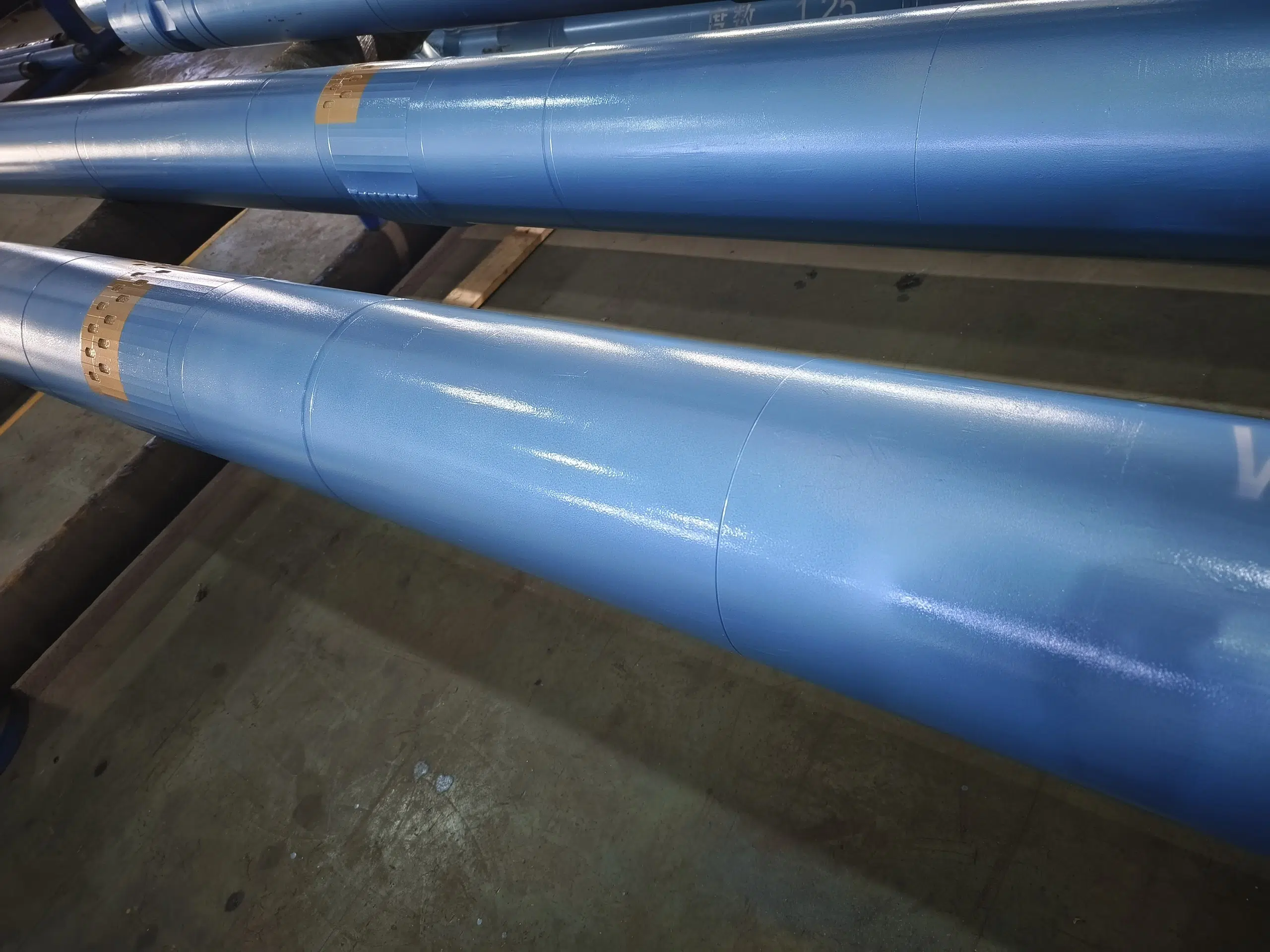
Real Mud Motor Assemblies & Stabilizer Components
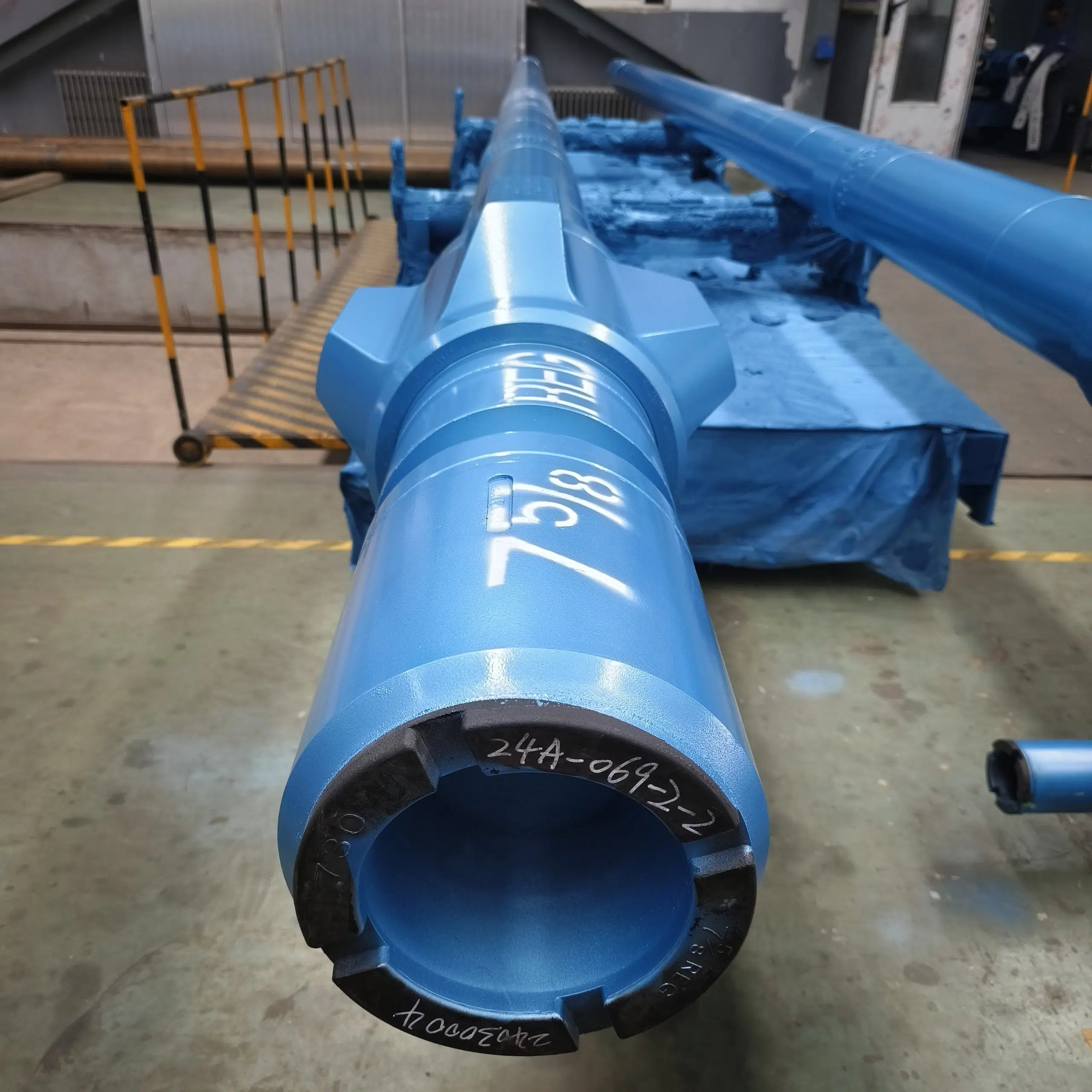
These shop-floor photos show finished mud motor assemblies and stabilizer components for visual review before specification confirmation. Buyers can compare component form, coating condition, and assembly reference points alongside the performance data.
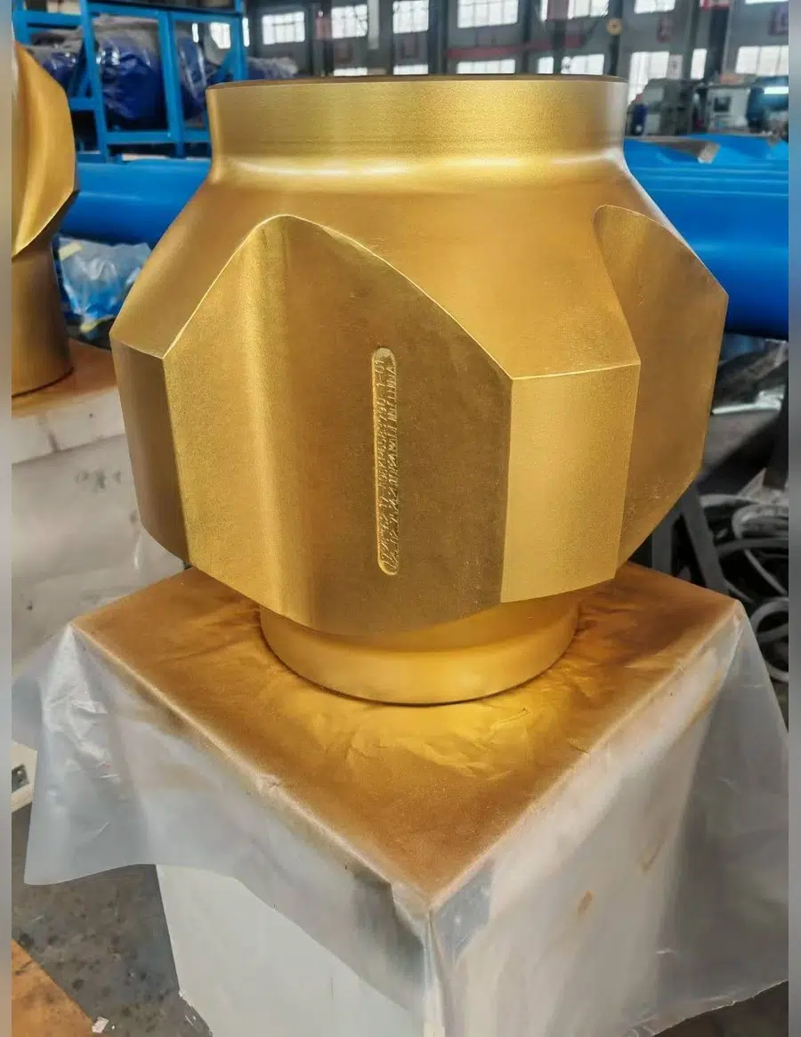
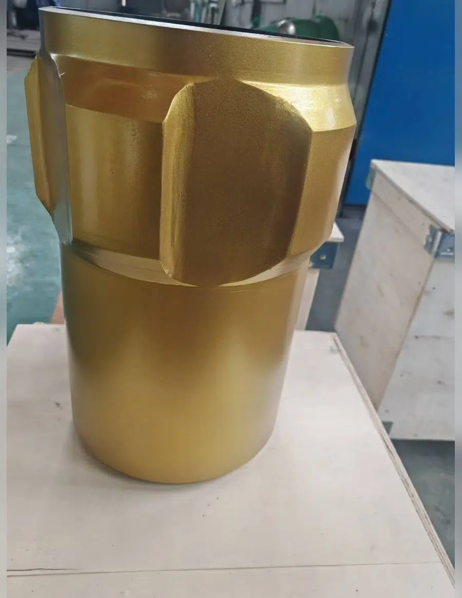
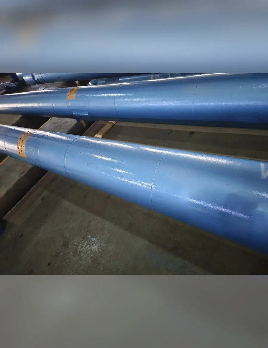
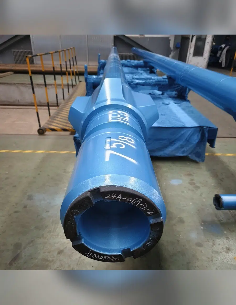
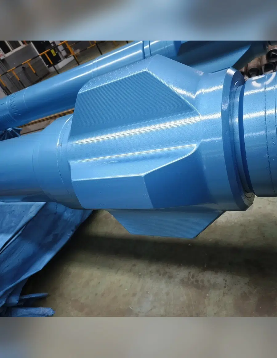
Stabilizer component – view 1Stabilizer component – view 2Finished motor assembly – view 1Finished motor assembly – view 2Finished motor assembly – view 3
Mud Motor vs Rotary-Only Drilling & Rotary Steerable Systems, 6-Point Performance Scorecard
There’s no universal winner between a positive displacement motor and a rotary steerable system (RSS) — the right choice depend on formation width, precision requirements, and budget, not on which technology is newer. In a widely-cited Drilling Contractor (IADC) industry comparison, high-performance mud motors were shown delivering daily cost savings of 50% or more over an RSS in broad-zone applications, while RSS technology held a real precision advantage in narrow target zones, the underlying cost/precision tradeoff still holds today even though the specific field figures date to that 2012 publication, and RSS pricing and capability have both moved since.[1] The replacement cost of losing either tool downhole is part of that calculation regardless of the exact dollar figure in your region and year.
| Factor | Rotary-Only (No Motor) | Mud Motor (PDM) | Rotary Steerable (RSS) |
|---|---|---|---|
| Directional Control | None — straight hole only | Sliding with bent housing, 0–3° on Welong models | Continuous rotation, precise toolface control |
| N/A | 50%+ lower[1] | Baseline (higher) | |
| Lost-in-Hole Exposure | Low | Can exceed $1,000,000[1] | |
| Best-Fit Formation | Soft, straight intervals | Broad target zones, less precision-critical | Narrow zones, as tight as 1½ ft[1] |
| Hole Cleaning | Continuous rotation aids cleaning | Weaker during sliding intervals[1] | Continuous rotation, better cuttings suspension[1] |
| Bit Compatibility | All bit types | All bit types, including non-RSS-compatible bits | Limited bit size/speed selection[1] |
50%+
Mud Motor and RSS Selection Considerations
Source: Drilling Contractor magazine (IADC), “Reservoir drives choice of RSS vs mud motors” (2012) — a widely-cited industry comparison, not a Welong-specific measurement; treat the cost/precision tradeoff as directional, not a current-year quote
Power Conversion & Steering Mechanics
Both technologies convert hydraulic power into mechanical power at the bit, but they get there differently: sliding drilling with a motor hold the drill string stationary while the bent housing points the curved section of the wellbore, whereas rotary drilling with an RSS keeps the string turning throughout. Weight on bit (WOB) and mechanical specific energy both shift measurably between the two modes, which is why a driller watching the power curve on surface can usually tell which mode is active without checking the toolface readout. Bit selection matters here too, a PDC bit (polycrystalline diamond compact) pairs well with either technology, while measurement while drilling (MWD) sensors report WOB and toolface regardless of which tool is doing the steering.
The Honest Read: Strategic Application
Choose between a mud motor and an RSS from the formation width, drilling objectives, and risk tolerance. Confirm the required motor configuration for the planned interval.
Field-Proven Engineering, Hollow Rotor, Uniform-Wall Stator & Oil-Sealed Shaft
The success or failure of this lineup hinges on three design decisions, and no they aren’t marketing mumbo-jumbo, they’re concrete, mechanical components responsible for the spec sheet’s figures.
Hollow Rotor.
A hollow rotor core increases flow rate through the power section without a proportional increase in motor OD, which is what lets the smaller-bore models (1⅞″–3″ hole size) still deliver usable horsepower in a tight annulus. More flow area at a given size translates directly into more available horsepower at the bit.
Uniform Wall Thickness Stator.
An even elastomer layer around the stator bore distributes load more evenly across the power section than a tapered or inconsistent-thickness design, which is what supports the higher output-power figures on the larger models (up to 64 kW on the WL5LZ120×7.0V).
Oil-Sealed Transmission Shaft.
Sealing the drive shaft and bearing assembly, housed in the transmission section between the power section and the bit, in oil rather than exposing it to raw drilling fluid extends the interval between required maintenance, which is the practical driver behind longer single-trip working time. The bearing section absorbs the radial and thrust loads the bit generate and keeps rotor motion concentric under load; oil-based lubrication in this section is what protects against premature wear from those loads. Every dimension in the spec table above ultimately traces back to how the stator and rotor pair is sized for that model.
Engineering Note, What Actually Wears Out
Stator elastomer degradation can be accelerated by poor mud conditioning, high solids, aggressive chemistry, or temperatures beyond the motor rating. Maintain drilling fluid within the selected motor’s rated window and follow the mud program.
Unlike a generic spec sheet that lists features without explaining why they matter, each design choice above traces back to a specific field problem: the honest version of “high flow rate” is that a hollow rotor is what makes it possible in a small-bore application, not a marketing adjective. For the selected motor, confirm the responsible manufacturer, feature configuration, verification method, and torque and power values against the quotation and supplier records.
Certifications & Quality Control, In-Process, Final & Third-Party Inspection
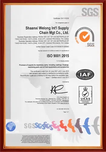
For the selected drilling-mud-motor order, the quotation identifies the responsible manufacturer, in-process and final inspection scope, and required records. Third-party inspection by SGS, DNV, or another qualified provider can be arranged when requested.
In-Process Inspection
Scope confirmed per order
SGS / DNV Available
Third-party, on request
Final Inspection
Scope confirmed per order
API 7-1 / 7-2 Connections
Rotary-shouldered dimensions
For supplier qualification, confirm the specific manufacturing documentation and inspection scope required for the selected mud motor at RFQ.
Procurement Guide, Shipping, Incoterms & Lead Time
High-Performance Drilling Mud Motors — Advanced B2B Solutions
UDTECH PERFORMANCE
Drilling Mud Motor Interactive Tools
Drilling Mud Motor Model Selector
Enter your target hole size and required torque to see which Welong models fit — matched directly against the 8-model spec table, no placeholder ranges.
Mud Motor (PDM) or Rotary Steerable System? — 3-Question Guide
There is no universal winner between the two — this uses the same formation-width / precision / cost logic published in industry comparison data to point you toward the right tool for your well.
Connection Compatibility Checker
Select the connection designation on your current drill string to see which Welong drilling mud motor models match — cross-referenced against the API 7-1/7-2 rotary-shouldered connection family.
FAQ
What is a drilling mud motor (PDM) and how does it work?
A drilling mud motor, also known as a positive displacement motor (PDM), is a downhole tool that translates circulating drilling fluid hydraulic energy into bit-end mechanical rotation. Flow of drilling fluid through a gap in a rotor and stator within the motor’s power section creates differential pressure that spins a rotor inside the housing; the rotor drive the bit independently of the drill string above it.
What’s the real difference between a mud motor (PDM) and a rotary steerable system (RSS)?
A mud motor steers by sliding with a bent housing and provides bit rotation only while sliding; an RSS steers while rotating the full drill string continuously, giving tighter directional control and better hole cleaning at a higher cost per day. Published comparison data shows mud motors running 50%+ lower daily cost, while RSS wins on precision in narrow target zones, neither tool is universally better, the formation and target width decide it.
How do I choose the right model from an 8-model lineup?
Start with your planned hole size and match it against the Hole Size column in the selection table above, then check working torque against your formation’s expected drilling requirements. Because lithology, mud weight, inclination and dogleg severity all affect real-world performance beyond a catalog spec, we recommend confirming your shortlist with our engineering team before ordering.
What connection types does the Welong lineup use, and how do I check compatibility?
Connections range from NC12 on the smallest model to 3½″ REG on the largest, following the rotary-shouldered connection dimensions in the API 7-1/7-2 standard family. Compare the Connection Top REG / Down REG rows in the spec table against your current drill string’s connection designation before ordering.
How should operators qualify a new mud motor supplier alongside an MWD or directional-drilling service provider?
In practice, most operating teams evaluate a motor supplier on inspection process transparency, connection/spec documentation accuracy, and responsiveness during the RFQ stage, separately from, but in coordination with, whichever MWD/directional service company is running the job, since the motor and MWD tools need to fit the same BHA.
What actually determines a mud motor’s service life?
Stator elastomer condition depends on mud conditioning, solids content, and operating temperature. Keep drilling fluid within the selected motor’s rated window and follow the mud program.
What quality checks happen before a Welong motor ships?
The quotation identifies the in-process and final inspection scope for the selected motor. Third-party inspection can be requested when independent verification is required.
Can Welong customize a motor outside the standard 8-model spec table?
Provide the target hole size, torque requirement, and connection standard so the engineering team can confirm whether a standard model fits or a customized configuration is needed.
Is a positive displacement motor suitable for both vertical and directional wells?
Yes. Run without sliding, a PDM drills a straight rotary interval like any rotary assembly; engaged with the bent housing in slide mode, the same motor delivers directional control. That dual capability is part of why PDMs remain widely used across both vertical and directional programs decades after the technology was introduced.
What shipping and trade terms does Welong support?
Sea, air, and rail transport, with FOB and CIF terms for sea freight and DAP/DDP for delivered arrangements under current Incoterms 2020 conventions. If your paperwork references the older DDU term, ask your procurement team to update it to DAP, its Incoterms 2020 equivalent.
Procurement & Capability
Drilling Mud Motor Capability Review
China Welong reviews the buyer drawing, product specification and inspection scope before quotation.
This review is scoped to the Drilling Mud Motor configurations set out in the specification table on this page — 13 documented rows covering Model, WL5LZx7.0IV, WL5LZ73x7.0III and WL5LZ80x7.0III.
24 hEngineer-reviewed quotation on business days
2001Founded in 2001
30+30+ engineers on staff
5 yrStamped serial traceability
Quotation Scope and Commercial Terms
Pricing is prepared against the selected product configuration, material route, inspection scope and shipment terms.
- Quotes are returned within 24 hours on business days, reviewed by an engineer.
- T/T or L/C by wire transfer.
- We ship EXW, FOB, CFR or CIF; other Incoterms on request.
- We work from 2D drawings and 3D CAD models (AutoCAD, Pro/ENGINEER, SolidWorks; .dwg and .igs).
Production Planning
Production timing is confirmed with the quotation after quantity, process route and finishing scope are reviewed.
- We hold agreed items in stock and ship against your release to shorten delivery. Feasibility is confirmed at drawing review.
- Manufacturing at Xi'an, Shaanxi and at Jiyuan, Henan.
- 0.01 mm machining precision.
- Material standards to ISO, BS, ASTM, ASME, DIN, JIS and GB.
- Orders ship in standard export wooden cases, or the packing you specify.
Order Review and Responsibility
The responsible manufacturer, inspection scope and document package are identified for the selected item.
- Every quotation states whether the item is made in our own works or by an approved supplier we developed and supervise.
- We develop, audit and supervise the mills and workshops that make your parts: material mills are re-audited every two years and approved by Welong before they run your order.
- Forgings from 0.2 to 50 tons.
Specification and Inspection Evidence
The specification table on this page is the technical basis for this review: its numeric rows define what we quote, manufacture and inspect against.
- Each piece carries a stamped serial number and stays traceable for five years to its chemical composition, mechanical properties and measurement report, with the test coupon retained.
- An EN 10204-3.1B material certificate with chemical composition and mechanical properties, a dimensional measurement report, and UT and MT reports ships with your order.
- Inspection is by coordinate measuring machine, ultrasonic, magnetic particle and X-ray.
Request a Product Review
Send the drawing, product specification and inspection requirements for a quotation review.
![Choke & Kill Hose: [Field Guide]](https://welongoiltools.com/wp-content/uploads/2026/07/choke-kill-hose-guide-featured-1-150x150.png)